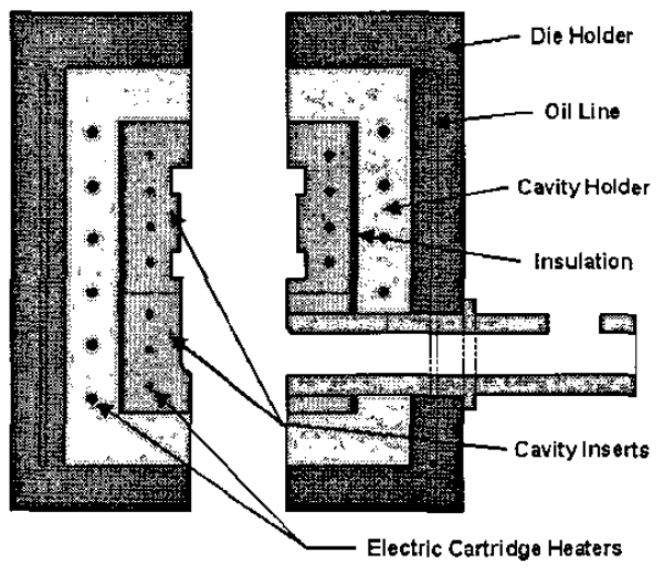
Fig. 2. Schematic illustration of the placement of electric
resistance heaters and insulation in the die material tests.
Fig. 2. Schematic illustration of the placement of electric
resistance heaters and insulation in the die material tests.
Fig. 2. Schematic illustration of the placement of electric
resistance heaters and insulation in the die material tests.
Fig. 2. Schematic illustration of the placement of electric
resistance heaters and insulation in the die material tests.