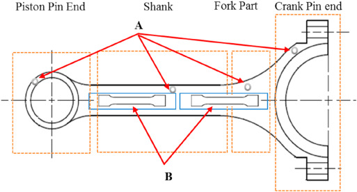
Fig. 2. Schematic of the sampling position of the connecting rod (A = microstructure observation and hardness test samples; B = tensile test sample).
Fig. 2. Schematic of the sampling position of the connecting rod (A = microstructure observation and hardness test samples; B = tensile test sample).