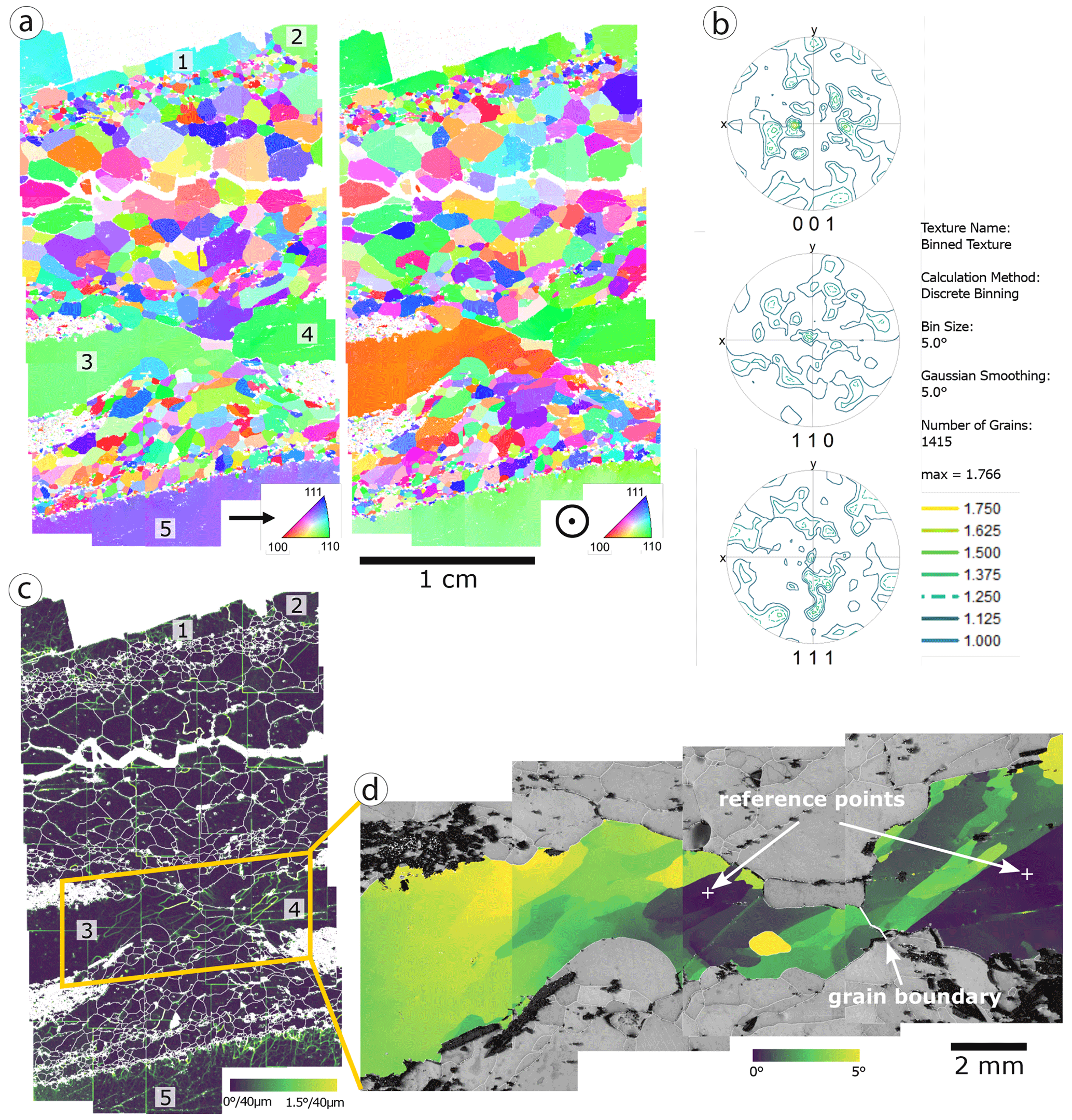
Figure 8(a) Inverse pole figure maps for halite grains with large Kristallbrocken grains labelled 1–5. (b) Pole figures of fine-grained matrix halite excluding five Kristallbrocken grains show no significant crystallographic preferred orientation (CPO). (c) Kernel average misorientation (KAM) map overlaid with white low- and high-angle grain boundaries (misorientation >5∘). KAM map was calculated over a distance of 40 µm (second neighbour) with a threshold of 3∘ in order to enhance the small-angle subgrain boundaries. KAM shows subgrain-free matrix halite with few exceptions in large matrix halite grains, Kristallbrocken 1 and 5 with subgrains, and subgrains in boudin necks of Kristallbrocken 3 and 4. (d) Cumulative reference orientation deviation map over the areas of Kristallbrocken 3 and 4, based on more highly resolved EBSD measurements. Reference points for each of the two grains are indicated. Panels (a) and (b) consist of 30 individual measurements, which due to image distortion under 70∘ tilt cannot be stitched perfectly. Therefore, in some cases an artificial separation of areas belonging to the same grain is visible
Figure 8(a) Inverse pole figure maps for halite grains with large Kristallbrocken grains labelled 1–5. (b) Pole figures of fine-grained matrix halite excluding five Kristallbrocken grains show no significant crystallographic preferred orientation (CPO). (c) Kernel average misorientation (KAM) map overlaid with white low- and high-angle grain boundaries (misorientation >5∘). KAM map was calculated over a distance of 40 µm (second neighbour) with a threshold of 3∘ in order to enhance the small-angle subgrain boundaries. KAM shows subgrain-free matrix halite with few exceptions in large matrix halite grains, Kristallbrocken 1 and 5 with subgrains, and subgrains in boudin necks of Kristallbrocken 3 and 4. (d) Cumulative reference orientation deviation map over the areas of Kristallbrocken 3 and 4, based on more highly resolved EBSD measurements. Reference points for each of the two grains are indicated. Panels (a) and (b) consist of 30 individual measurements, which due to image distortion under 70∘ tilt cannot be stitched perfectly. Therefore, in some cases an artificial separation of areas belonging to the same grain is visible