본 소개 자료는 "[Metals (MDPI)]"에서 발행한 논문 "[Experimental and Numerical Study of an Automotive Component Produced with Innovative Ceramic Core in High Pressure Die Casting (HPDC)]"를 기반으로 합니다.
1. 개요:
- 논문 제목: Experimental and Numerical Study of an Automotive Component Produced with Innovative Ceramic Core in High Pressure Die Casting (HPDC)
- 저자: Giovanna Cornacchia, Daniele Dioni, Michela Faccoli, Claudio Gislon, Luigi Solazzi, Andrea Panvini and Silvia Cecchel
- 발행 연도: 2019
- 발행 학술지/학회: Metals (MDPI)
- 키워드: non-ferrous alloys; ceramic core; FEA; HPDC; de-coring; material characterization (비철 합금; 세라믹 코어; 유한요소해석; 고압 다이캐스팅; 코어 제거; 재료 특성 분석)
2. 초록:
경량화 및 재료 대체는 자동차 산업에서 증가하는 추세입니다. 고압 다이캐스팅(HPDC)은 경합금의 대량 생산을 위한 전통적인 주조 기술이며, 최근에는 복잡하고 얇은 형상의 자동차 부품과 같은 중요 부품 제조에 널리 적용되고 있습니다. 그러나 이 저렴한 기술의 주요 제약은 중공 단면이나 언더컷이 있는 부품을 설계하고 구현하기 어렵다는 점입니다. HPDC의 경쟁력을 더욱 높이는 혁신적인 방법은 HPDC에서 사용되는 고압을 견딜 수 있는 새로운 분실 코어(lost core)를 사용하여 복잡한 언더컷 형상의 부품을 만드는 것입니다. 본 논문은 HPDC를 이용한 승용차용 알루미늄 크로스멤버 생산에 혁신적인 세라믹 분실 코어를 사용하는 것을 연구합니다. 먼저, 크로스멤버 설계를 개선하고 기술적 특징을 확인하기 위해 공정 및 구조 시뮬레이션을 수행했습니다. 그 결과를 바탕으로 공정 변수를 선정하고 최종적으로 특성을 분석할 프로토타입을 제작했습니다. 이러한 분석은 세라믹 코어를 사용하여 HPDC로 중공 부품을 생산할 수 있는 가능성을 보여줍니다.
3. 서론:
자동차 산업은 차량 성능 개선, 연비 향상, 배기가스 저감을 위해 경량 부품을 점점 더 요구하고 있습니다. 고압 다이캐스팅(HPDC)은 높은 생산성, 저비용, 정밀 형상(near-net shape)의 알루미늄 부품 생산에 경쟁력 있는 기술입니다. 그러나 HPDC는 전통적으로 복잡한 중공 단면이나 언더컷이 있는 부품 생산에 어려움을 겪습니다. 이는 종종 금속 이동 코어를 필요로 하여, 중력 주조에서 사용되는 분실 코어(lost core)에 비해 설계 자유도를 제한합니다. 이러한 한계를 극복하기 위해서는 HPDC의 고압 및 고속 유동에 적합한 분실 코어가 필요합니다. HPDC용 염(salt) 코어에 대한 연구가 있었지만 여전히 과제가 남아 있습니다. 본 논문은 복잡한 형상과 우수한 공차를 위해 사출 성형으로 생산되며, 높은 HPDC 압력(1000 bar 이상)을 견디고 가스를 방출하지 않는 혁신적인 세라믹 분실 코어의 사용을 탐구합니다. 이 연구는 이러한 세라믹 코어를 사용하여 HPDC로 승용차용 알루미늄 크로스멤버를 재설계, 생산 및 실현 가능성을 입증하는 데 중점을 둡니다. 목표는 기존 방식에 비해 무게 감소, 비틀림 강성 증가, 생산 시간 단축과 같은 이점을 달성하는 것입니다.
4. 연구 요약:
연구 주제의 배경:
자동차 분야의 경량화 추세는 알루미늄과 같은 경합금을 선호하게 합니다. HPDC는 높은 생산성과 비용 효율성 때문에 이러한 합금의 주요 제조 방법입니다. 그러나 중량 대비 강성이 우수한 복잡한 중공 부품은 기존 HPDC 방식(금속 코어 사용)으로는 언더컷 및 내부 공동 구현이 어렵거나, 기존 분실 코어(예: 모래, 염)가 높은 사출 압력과 호환되지 않아 생산하기 어렵습니다.
기존 연구 현황:
기존 연구에서는 주조 공정을 위한 다양한 소모성 코어(모래, 염, 금속, 유기 재료)를 탐구했습니다. 특히 HPDC 적용을 위해 염 코어가 주목받았으며, 그 강도와 공정 변수에 대한 연구가 진행되었습니다. 실린더 블록과 같은 부품에 HPDC에서 가용성 코어를 사용하는 특허도 존재합니다. 그러나 요구되는 강도와 공정 신뢰성을 달성하는 것은 여전히 과제입니다. 사출 성형으로 생산된 세라믹 코어는 우수한 치수 공차, 낮은 표면 거칠기, 주조 중 가스 방출 부재 등의 잠재적 이점을 제공하여 더 높은 기계적 특성을 보장할 수 있습니다. 침출(leaching) 및 고압 워터젯과 같은 코어 제거 방법이 존재하지만, 복잡한 내부 공동에서 저항성 있는 코어를 제거하는 것은 고려해야 할 사항입니다.
연구 목적:
주요 목표는 혁신적인 세라믹 분실 코어를 사용하여 HPDC 공법으로 복잡한 중공 자동차 부품(알루미늄 승용차 크로스멤버)을 생산하는 것의 실현 가능성을 조사하고 입증하는 것이었습니다. 이를 위해 부품 재설계, 공정 및 구조 성능 시뮬레이션, 프로토타입 생산, 코어 및 최종 주조 부품의 특성 분석을 수행했습니다.
핵심 연구 내용:
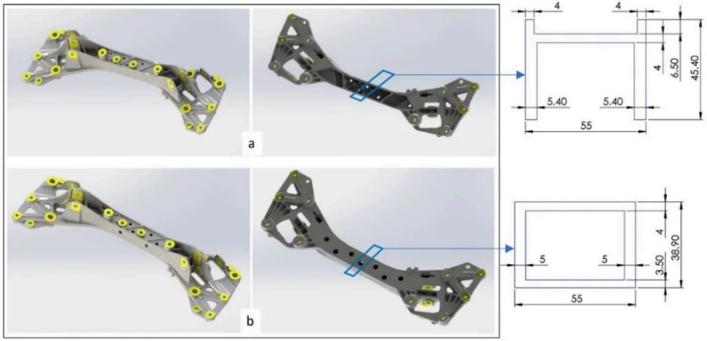
본 연구는 기존의 개방형 단면 알루미늄 크로스멤버(EN AC-43500 합금)를 세라믹 코어(Al2O3 + SiO2 + K2O 기반)를 사용하여 폐쇄형 박스 단면으로 재설계하는 것을 포함했습니다. 유한요소해석(FEA)을 사용하여 원본 설계와 수정된 설계의 구조적 성능(모달 해석, 좌굴)을 비교했습니다. 전산유체역학(CFD) 시뮬레이션을 수행하여 세라믹 코어의 열 특성을 고려하여 두 설계 모두에 대한 HPDC 공정(충전, 응고, 공기 혼입)을 분석했습니다. 실험 작업에는 다양한 소결 온도로 생산된 세라믹 코어의 특성 분석(밀도, 코어 제거 방법, 3점 굽힘 시험을 통한 기계적 특성)이 포함되었습니다. 선택된 코어 유형을 사용하여 HPDC 프로토타입을 제조했습니다. 마지막으로, 주조된 프로토타입은 미세구조 분석(OM, SEM/EDS) 및 비커스 미세경도 시험을 통해 특성을 분석했습니다.
5. 연구 방법론
연구 설계:
본 연구는 수치 시뮬레이션과 실험적 검증을 결합한 방식을 사용했습니다. 기존 자동차 크로스멤버 설계를 세라믹 코어를 통해 중공 단면을 포함하도록 수정했습니다. 원본 개방형 단면 설계와 새로운 폐쇄형 단면(박스형) 설계 간의 비교 분석(수치적 및 암묵적 실험적)을 수행했습니다. 연구는 부품 재설계 -> 수치 시뮬레이션(구조 FEA 및 공정 CFD) -> 세라믹 코어 재료 선정 및 특성 분석 -> HPDC를 통한 프로토타입 제조 -> 최종 부품 특성 분석 순서로 진행되었습니다.
데이터 수집 및 분석 방법:
- 수치 시뮬레이션:
- 구조 해석 (FEA): Autodesk Simulation® 소프트웨어를 사용하여 포물선 벽돌 요소로 수행했습니다. 자유-자유 및 고정 경계 조건에서의 모달 해석(고유 진동수)과 적용된 힘 및 모멘트 하중 하에서의 좌굴 해석을 수행했습니다.
- 공정 시뮬레이션 (CFD): PiQ2의 CastleBody 소프트웨어를 사용하여 압축성-비압축성 이중상 유체 체적(VOF) 공식을 적용하여 수행했습니다. 시뮬레이션은 알루미늄 합금(EN AC-43500)과 세라믹 코어 인서트의 열 특성을 모두 고려하여 금형 충전, 응고, 공기 혼입 및 잠재적 결함을 분석했습니다. 국부적 상세화가 적용된 육면체 메쉬(약 1,000,000개 셀)를 사용했습니다.
- 실험적 특성 분석:
- 세라믹 코어: 에탄올을 사용한 비중병(pycnometer)으로 밀도를 측정했습니다. 화학적 침출(다양한 산) 및 고압 워터젯을 사용하여 코어 제거 효율성을 테스트했습니다. 3점 굽힘 시험(Instron 3369)을 통해 UNI EN 843-1 및 UNI EN 843-3에 따라 기계적 특성(굽힘 강도 σf, 영률 E)을 결정했습니다.
- HPDC 부품: IDRA OLS2000 HPDC 기계에서 프로토타입을 생산했습니다. 횡단면에 대한 미세구조를 광학 현미경(OM - Leica DMI 5000M) 및 주사 전자 현미경(SEM - LEO EVO 40)과 에너지 분산 분광법(EDS - Link Analytical eXL)을 사용하여 분석했습니다. ASTM E92-16 및 ASTM E140-02에 따라 Micro Duromat 4000 Reichert Jung 기기를 사용하여 단면 전체에 걸쳐 비커스 미세경도(HV0.3)를 측정했습니다.
연구 주제 및 범위:
본 연구는 자동차 구조 부품(크로스멤버)을 위한 HPDC 공정에서 혁신적인 세라믹 분실 코어의 적용에 초점을 맞췄습니다. 연구 범위는 다음과 같습니다:
- 크로스멤버의 기하학적 재설계 (개방형에서 폐쇄형 단면으로).
- 비교 구조 성능 분석 (강성, 좌굴 저항성).
- 유체 유동, 열 전달, 응고 및 결함 예측(공기 혼입, 콜드 조인트, 수축)을 포함한 HPDC 공정 실현 가능성 시뮬레이션.
- Al2O3 + SiO2 + K2O 기반 세라믹 코어의 특성 분석 (물리적, 코어 제거를 위한 화학적 저항성, 기계적 특성).
- EN AC-43500 알루미늄 합금을 사용한 프로토타입의 실험적 생산.
- 알루미늄 합금과 잔류 세라믹/서멧 재료 사이의 계면을 포함한 최종 주조 부품의 야금학적 특성 분석.
6. 주요 결과:
주요 결과:
- 폐쇄형 박스 단면으로 재설계된 크로스멤버는 원본 개방형 프로파일에 비해 약간의 무게 감소를 달성했습니다(3.93 kg 대 3.95 kg).
- FEA 시뮬레이션 결과, 새로운 설계가 원본 설계에 비해 우수한 구조적 성능을 보였습니다: 더 높은 고유 진동수(강성 증가 의미, 예: 자유-자유 조건에서 첫 번째 비틀림 진동수가 약 54.3% 증가) 및 힘과 모멘트 하중 조건 모두에서 상당히 높은 좌굴 하중 계수를 나타냈습니다.
- CFD 공정 시뮬레이션은 세라믹 코어를 사용한 HPDC 공정의 실현 가능성을 확인했습니다. 예측된 주조 품질(공기 혼입, 응고 패턴, 잠재적 결함)은 코어가 없는 전통적인 HPDC 공정과 매우 유사했습니다. 시뮬레이션 파라미터(예: 충전 시간 ~0.2초, 응고 시간 ~8.4초)는 표준 HPDC 관행과 일치했습니다.
- 세라믹 코어 특성 분석 결과 밀도는 약 1.92-1.98 g/cm³였습니다. 화학적 침출 테스트 결과 HF 용액만이 세라믹을 식각했지만, 이는 알루미늄에 심각한 손상을 입혔습니다. 고압 워터젯이 효과적이고 손상 없는 코어 제거 방법으로 확인되었습니다. 기계적 테스트(3점 굽힘) 결과, 굽힘 강도와 영률은 소결 온도가 증가함에 따라 증가했으며, 프로토타입 제작에는 "c-1110 °C" 변형이 선택되었습니다.
- 선택된 세라믹 코어를 사용하여 약 100개의 중공 크로스멤버 프로토타입이 HPDC로 성공적으로 생산되었으며, 이후 워터젯으로 코어가 제거되었습니다. 제조 사이클 시간은 약 70초였습니다.
- 프로토타입의 미세구조 분석 결과, EN AC-43500 합금의 예상 구조(α-Al 기지, Al-Si 공정, α-Al15(Mn,Fe)3Si2와 같은 금속간 화합물)가 나타났습니다. 일부 영역에서 알루미늄과 세라믹 코어 사이의 계면에 얇은(~100 µm) 서멧 층(세라믹-금속 혼합물)이 관찰되었지만, 알루미늄과의 우수한 밀착성을 보였고 적용에 해로운 것으로 간주되지 않았습니다.
- 부품 단면에 걸친 비커스 미세경도 측정 결과 75-90 HV0.3 범위의 값이 나왔으며, 이는 이 합금 및 공정에 일반적인 값으로, 코어와 얇은 서멧 층의 존재가 벌크 재료의 전반적인 기계적 특성에 부정적인 영향을 미치지 않음을 나타냅니다.
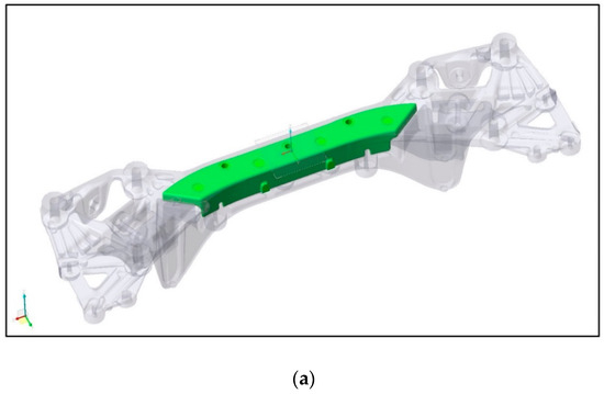
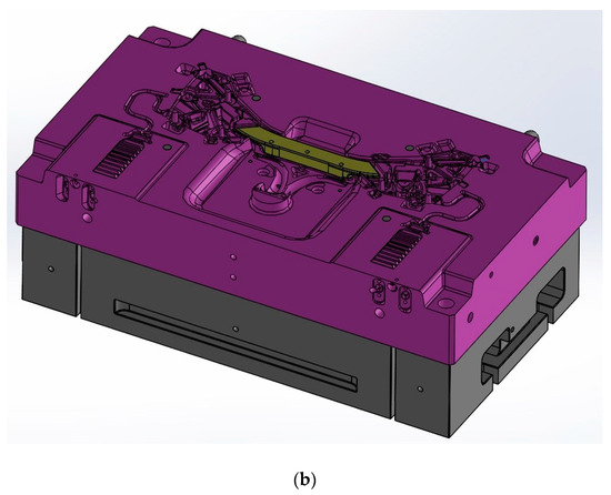
Figure 2. (a) 3D model of the closed profile crossbeam with ceramic core. (b) The geometry and the positioning solutions in the mold cavity adopted for the ceramic core.
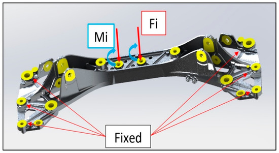
Figure 3. Buckling analysis model: boundary condition and load cases.Table 2. FEM simulation parameters.
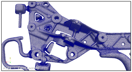
Figure 4. Local mesh refinement.
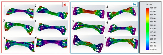
Figure 5. Displacement trend for the first six vibration modes for original geometry: (a) free-free boundary conditions and (b) fixed conditions.

Figure 6. Displacement trend for the first six vibration modes for new geometry: (a) free-free boundary conditions and (b) fixed conditions.

Figure 7. Displacement trend for the first four deformations for original geometry: (a) load case 1 (F); (b) load case 2 (M).

Figure 8. Displacement trend for the first four deformations for new geometry: (a) load case 1 (F); (b) load case 2 (M).
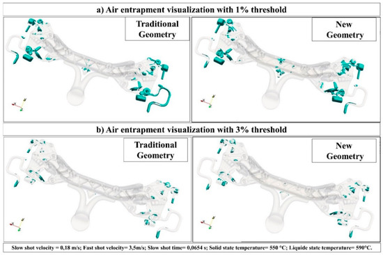
Figure 9. Air entrapment visualization (a) with 1% threshold and (b) with 3% threshold for traditional and new geometry.
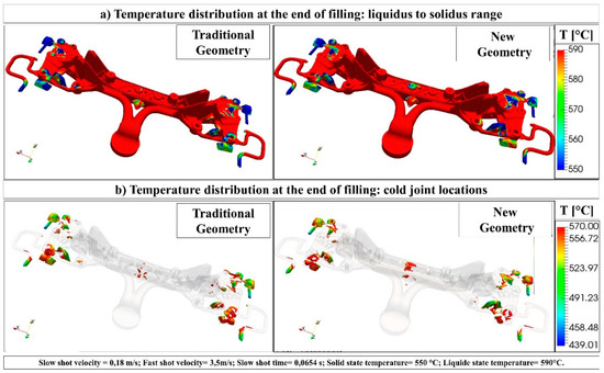
Figure 10. (a) Temperature distribution at the end of filling: liquidus to solidus range; (b) Temperature distribution at the end of filling: cold joint locations.

Figure 11. Results of solidification analysis.Figure 10a,b shows the temperature distribution of the alloy at the end of filling in the range between liquidus and solidus temperatures.
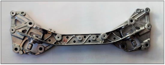
Figure 12. Hollowed aluminum high pressure die casting component.
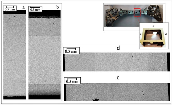
Figure 13. Collage of various micrographs of the transverse sections of the hollowed crossbeam.
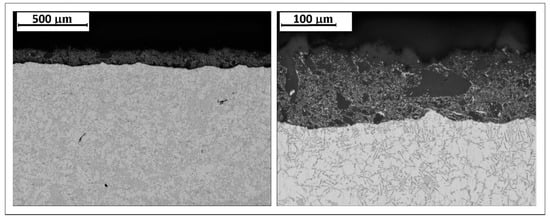
Figure 14. Optical microscope details of the transverse sections of the hollowed crossbeam.
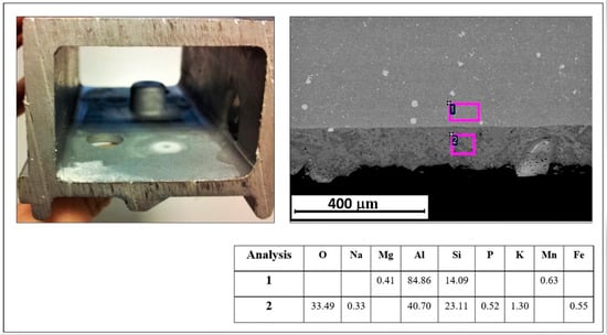
Figure 15. Visual inspection on cermet and SEM image with results of EDS analysis (wt%).
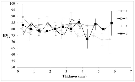
Figure 16. Vickers microhardness HV0.3 variation with respect to the thickness along the transverse section of .
그림 목록:
- Figure 1. 3D design and schematic sketch of the section profile of (a) original crossbeam (b) modified crossbeam. The dimensions are expressed in (mm).
- Figure 2. (a) 3D model of the closed profile crossbeam with ceramic core. (b) The geometry and the positioning solutions in the mold cavity adopted for the ceramic core.
- Figure 3. Buckling analysis model: boundary condition and load cases.
- Figure 4. Local mesh refinement.
- Figure 5. Displacement trend for the first six vibration modes for original geometry: (a) free-free boundary conditions and (b) fixed conditions.
- Figure 6. Displacement trend for the first six vibration modes for new geometry: (a) free-free boundary conditions and (b) fixed conditions.
- Figure 7. Displacement trend for the first four deformations for original geometry: (a) load case 1 (F); (b) load case 2 (M).
- Figure 8. Displacement trend for the first four deformations for new geometry: (a) load case 1 (F); (b) load case 2 (M).
- Figure 9. Air entrapment visualization (a) with 1% threshold and (b) with 3% threshold for traditional and new geometry.
- Figure 10. (a) Temperature distribution at the end of filling: liquidus to solidus range; (b) Temperature distribution at the end of filling: cold joint locations.
- Figure 11. Results of solidification analysis.
- Figure 12. Hollowed aluminum high pressure die casting component.
- Figure 13. Collage of various micrographs of the transverse sections of the hollowed crossbeam.
- Figure 14. Optical microscope details of the transverse sections of the hollowed crossbeam.
- Figure 15. Visual inspection on cermet and SEM image with results of EDS analysis (wt%).
- Figure 16. Vickers microhardness HV0.3 variation with respect to the thickness along the transverse section of Figure 13.
7. 결론:
본 연구는 혁신적인 세라믹 분실 코어를 사용하여 HPDC 공법으로 더 가볍고 구조적으로 개선된 안전 관련 자동차 부품(알루미늄 크로스멤버)을 생산할 수 있는 가능성을 성공적으로 입증했습니다. 재설계된 박스형 구조는 원본 개방형 프로파일 설계에 비해 동적 거동(더 높은 고유 진동수)과 좌굴 저항성이 크게 향상되었음을 보여주었습니다. 공정 시뮬레이션은 세라믹 코어를 사용한 HPDC 공정이 전통적인 방법과 유사한 주조 품질을 달성할 수 있음을 확인했습니다. 실험적 특성 분석을 통해 적합한 세라믹 코어 특성과 효과적인 코어 제거 방법(고압 워터젯)을 확인했습니다. 생산된 프로토타입 분석 결과, 코어-금속 계면에 얇고 해롭지 않은 서멧 층이 존재함에도 불구하고 미세구조와 경도가 표준 HPDC 부품과 일치함을 확인했습니다. 이 결과는 세라믹 분실 코어를 사용한 HPDC가 복잡하고, 중공이며, 정밀 형상(near-net shape)의 부품을 대량으로 제조할 수 있는 우수한 잠재력을 가지고 있음을 보여줍니다. 이는 첨단 자동차 응용 분야에서 HPDC의 경쟁력을 높이고, 중공 구조물의 추가적인 경량화 및 설계 최적화 가능성을 열어줍니다.
8. 참고 문헌:
- [1] Chindamo, D.; Gadola, M. Reproduction of real-world road profiles on a four-poster rig for indoor vehicle chassis and suspension durability testing. Adv. Mech. Eng. 2017, 9, 1–10. [CrossRef]
- [2] Chiaberge, M. New Trends and Developments in Automotive Industry; InTech: London, UK, 2011; ISBN 978-953-307-999-8. [CrossRef]
- [3] Tempelman, E. Multi-Parametric study of the effect of materials substitution on life cycle energy use and waste generation of passenger car structures. Transp. Res. Part D Transp. Environ. 2011, 16, 479–485. [CrossRef]
- [4] Cecchel, S.; Chindamo, D.; Turrini, E.; Carnevale, C.; Cornacchia, G.; Gadola, M.; Panvini, A.; Volta, M.; Ferrario, D.; Golimbioschi, R. Impact of reduced mass of light commercial vehicles on fuel consumption, CO2 emissions, air quality, and socio-economic costs. Sci. Total Environ. 2018, 613–614, 409–417. [CrossRef] [PubMed]
- [5] Cecchel, S.; Ferrario, D.; Panvini, A.; Cornacchia, G. Lightweight of a cross beam for commercial vehicles: Development, testing and validation. Mater. Des. 2018, 149, 122–134. [CrossRef]
- [6] Cecchel, S.; Ferrario, D. Numerical and experimental analysis of a high pressure die casting Aluminum suspension cross beam for light commercial vehicles. La Metallurgia Italiana 2016, 6, 41–44.
- [7] Morello, L.; Rosti Rossini, L.; Pia, G.; Tonoli, A. The Automotive Body: Volume I: Components Design; Springer: New York, NY, USA, 2001; ISBN 978-94-007-0513-5.
- [8] Cecchel, S.; Cornacchia, G.; Panvini, A. Cradle-to-Gate Impact Assessment of a High-Pressure Die-Casting Safety-Relevant Automotive Component. JOM 2016, 8, 2443–2448. [CrossRef]
- [9] Cecchel, S.; Chindamo, D.; Collotta, M.; Cornacchia, G.; Panvini, A.; Tomasoni, G.; Gadola, M. Lightweighting in light commercial vehicles: Cradle-to-grave life cycle assessment of a safety relevant component. Int. J. Life Cycle Assess. 2018, 23, 1–12. [CrossRef]
- [10] Cecchel, S.; Collotta, M.; Cornacchia, G.; Panvini, A.; Tomasoni, G. A comparative cradle-to gate impact assessment: Primary and secondary aluminum automotive components case. La Metallurgia Italiana 2018, 2, 46–55.
- [11] Cecchel, S.; Cornacchia, G.; Gelfi, M. Corrosion behavior of primary and secondary AlSi High Pressure Die Casting alloys. Mater. Corros. 2017, 68, 961–969. [CrossRef]
- [12] Solazzi, L. Applied research for Weight Reduction of an industrial Trailer. FME Trans. 2012, 40, 57–62.
- [13] Solazzi, L. Wheel rims for industrial vehicles: Comparative and experimental analyses. Int. J. Heavy Veh. Syst. 2011, 18, 214–225. [CrossRef]
- [14] Hirsch, J. Aluminium in Innovative Light-Weight Car Design. Mater. Trans. 2011, 52, 818–824. [CrossRef]
- [15] Chindamo, D.; Lenzo, B.; Gadola, M. On the vehicle sideslip angle estimation: A literature review of methods, models and innovations. Appl. Sci. 2018, 8, 355. [CrossRef]
- [16] Henriksson, F.; Johansen, K. On Material Substitution in Automotive BIWs – From Steel to Aluminum Body Sides. Procedia CIRP 2016, 50, 683–688. [CrossRef]
- [17] Kelkar, A.; Roth, R.; Clark, J. Automobile Bodies: Can Aluminum Be an Economical Alternative To Steel? JOM 2001, 53, 28–32.
- [18] Zhoua, J.; Wana, X.; Lia, Y. Advanced aluminium products and manufacturing technologies applied on vehicles at the EuroCarBody conference. Mater. Proc. 2015, 2, 5015–5022. [CrossRef]
- [19] Fridlyander, I.N.; Sister, V.G.; Grushko, O.E.; Berstenev, V.V.; Sheveleva, L.M.; Ivanova, L.A. Aluminum alloys: Promising materials in the automotive industry. Met. Sci. Heat Treat. 2002, 44, 365–370. [CrossRef]
- [20] Dioni, D.; Cecchel, S.; Cornacchia, G.; Faccoli, M.; Panvini, A. Effects of artificial aging conditions on mechanical properties of gravity cast B356 aluminum alloy. Trans. Nonferrous Met. Soc. China 2015, 25, 1035–1042. [CrossRef]
- [21] Faccoli, M.; Dioni, D.; Cecchel, S.; Cornacchia, G.; Panvini, A. Optimization of heat treatment of gravity cast Sr-modified B356 aluminum alloy. Trans. Nonferrous Met. Soc. China 2017, 27, 1698–1706. [CrossRef]
- [22] Haracopos, B.; Fisher, T.P. The Technology of Gravity Die Casting; Hart Pub. Co.: Oxford, UK, 1968.
- [23] ASM. Metals Handbook, 10th ed.; ASM-Metals Park: Geauga, OH, USA, 1990.
- [24] Campbell, J.; Harding, R.A. Casting Technology; TALAT 2.0 [CD-ROM]; EAA: Bruxelles, Belgium, 2000.
- [25] Schleg, S.; Kamicki, D.P. Guide to casting and moulding processes. Engineered casting solutions. Technical Articles, 2000.
- [26] Brown, J.R. Foseco Non-Ferrous Foundryman’s Handbook; Elsevier: Oxford, UK, 1999; ISBN 9780080531878.
- [27] Street, A.C. The Diecasting Book, 2nd ed.; Portcullis Press: London, UK, 1990.
- [28] Nagendra Parashar, S.; Mittal, R.K. Elements of Manufacturing Processes; PHI learning Pvt. Ltd.: New Delhi, India, 2006.
- [29] Vinarcik, E.J. High Integrity Die Casting Processes; John Wiley & Sons: Hoboken, NJ, USA, 2002; ISBN 978-0-471-20131-1.
- [30] Andresen, W. Die Cast Engineering: A Hydraulic, Thermal, and Mechanical Process; CRC Press: Boca Raton, FL, USA, 2004.
- [31] Jelínek, P.; Adámková, E.; Mikšovský, F.; Beňo, J. Advances in technology of soluble cores for die castings. Arch. Foundry Eng. 2015, 15, 29–34. [CrossRef]
- [32] Pierri, D. Lost Core: New Perspectives in Die Casting. Available online: https://www.buhlergroup.com/northamerica/en/industry-solutions/die-casting/latest-news/details-7797.htm?title= (accessed on 9 February 2019).
- [33] Czerwinski, F.; Birsan, G.; Benkel, F.; Kasprzak, W.; Walker, M.J.; Smith, J.; Trinowski, D.; Musalem, I. Developing strong core technology for high pressure die casting. Automot. Mater. 2017, 8, 1–11.
- [34] Rupp, S.; Heppes, F. La rivoluzione nella pressofusione. Tecnico-Industria Fusoria 2017, 4, 72–76.
- [35] Donahue, R.J.; Degler, M.T. Congruent Melting Salt Alloys for Use as Salt Cores in High Pressure Die Casting. U.S Patent US9527131B1, 25 August 2014.
- [36] Radadiya, V.A.; Dave, K.G.; Patel, K.R. Design and analysis of salt core for a casting of alluminium alloys. Int. J. Adv. Eng. Res. Dev. 2015, 2, 344–348.
- [37] Jelinek, P.; Miksovsky, F.; Beoo, J.; Adamkova, E. Development of foundry cores based on inorganic salts. MTAEC9 2013, 47, 689–693.
- [38] Jelínek, P.; Adámková, E. Lost cores for high-pressure die casting. Arch. Foundry Eng. 2014, 14, 101–104. [CrossRef]
- [39] Yaokawa, J.; Miura, D.; Anzai, K.; Yamada, Y.; Yoshii, H. Strength of salt core composed of alkali carbonate and alkali chloride mixtures made by casting technique. Mater. Trans. 2007, 8, 1034–1041. [CrossRef]
- [40] Yaokawa, J.; Koichi, A.; Yamada, Y.; Yoshii, H. Strength of salt core for die casting. In Proceedings of the International Conference CastExpo ’05 NADCA, St. Louis, MO, USA, 16–19 April 2005; NADCA: St. Louis, MO, USA, 2005.
- [41] Fuchs, B.; Eibisch, H.; Körner, C. Core viability simulation for salt core technology in high-pressure die casting. Int. J. Metalcast. 2013, 7, 39–45. [CrossRef]
- [42] Fuchs, B.; Körner, C. Mesh resolution consideration for the viability prediction of lost salt cores in the high pressure die casting process. Prog. Comput. Fluid Dyn. 2014, 14, 24–30. [CrossRef]
- [43] Mizukusa, Y. Casting Apparatus and Casting Method for Producing Cylinder Block. U.S. Patent 5,690,159, 27 August 1996.
- [44] Ackerman, A.D.; Aula, H.A. Method of Making a Cast Aluminum Based Engine Block. U.S. Patent 4,446,906, 8 May 1984.
- [45] Brown, W.N.; Robinson, P.M. Soluble Metal Casting Cores Comprising a Water Soluble Salt and a Synthetic Resin. U.S. Patent 364,549, 22 July 1969.
- [46] Gibbons, W.A. Core or Filler of Fusible Material for Hollow Vulcanizable Articles. U.S. Patent 1,523,519, 20 January 1925.
- [47] Foreman, R.W. Mixture and Method for Preparing Casting Cores and Cores Prepared Thereby. U.S. Patent 4,840,219, 20 June 1989.
- [48] Sakoda, T. Water Soluble Core for Pressure Die Casting and Process for Making the Same. U.S. Patent 3,963,818, 15 June 1976.
- [49] Molina, R.; Moschini, R. Production of hollow components in high pressure die casting through the use of ceramic lost cores. In Proceedings of the International Conference High Tech Die Casting 2012, Vicenza, Italy, 9–10 April 2012.
- [50] Moschini, R.; Calzolaro, A.L. Method for Manufacturing Monolithic Hollow Bodies by Means of a Casting or Injection Moulding Process. Patent International Publication No WO 2011/061593 A1, 26 May 2011.
- [51] Solazzi, L. Innovative Bolted junction with high ductility for circular tubular element. J. Constr. Steel Res. 2015, 112, 175–182. [CrossRef]
- [52] Mats, G.; Larson, F.B. The Finite Element Method: Theory, Implementation and Applications; Springer: Berlin, Germany, 2010; ISBN 978-3-642-33286-9.
- [53] Dimitrios, G. Pavlou Essentials of Finite Element Method for Mechanical and Industrial Engineers; Elsevier: Amsterdam, The Netherlands, 2015; ISBN 978-0-12-802386-0.
- [54] Panvini, A.; Molin, D.; Gislon, C. Dual phase simulation for high pressure die casting: Overview and validation of its capabilities. In Proceedings of the HTDC Conference 2016, AIM, Venice, Italy, 22–23 June 2016.
- [55] Panvini, A.; Gislon, C. Air entrapment prediction in diecasting through dual phase simulation. In Proceedings of the Die Casting Congress Tabletop 2013, Louisville, KY, USA, 16–18 September 2013.
- [56] Miller, A. PQ2 and Gating Manual; NADCA: Arlington Heights, IL, USA, 2016.
- [57] UNI EN 843-1:2007. Advanced Technical Ceramics—Mechanical Properties of Monolithic Ceramics at Room Temperature—Part 1: Determination of Flexural Strength; NSAI: Dublin, Ireland, 2007.
- [58] UNI EN 843-2:2007. Advanced Technical Ceramics—Mechanical Properties of Monolithic Ceramics at Room Temperature—Part 2: Determination of Young’s Modulus, Shear Modulus and Poisson’s Ratio; NSAI: Dublin, Ireland, 2007.
- [59] Smith, J.H. An Introduction to Modern Vehicle Design; Elsevier: Oxford, UK, 2002; ISBN 07506 5044 3.
- [60] Pacejka, H.B. Tyre and Vehicle Dynamics, 2nd ed.; Butterworth-Heinemann: Oxford, UK, 2006; ISBN 0-7506-6918-7.
- [61] Franke, R.; Dragulin, D.; Zovi, A.; Casarotto, F. Progress in ductile aluminium high pressure die casting alloys for the automotive industry. La Metallurgia Italiana 2007, 5, 21–26.
- [62] Tinklepaugh, J.R.; James, R. Cermets; Reinhold Publishing Corporation: New York, NY, USA, 1960; ASIN B0007E6FO4.
- [63] Hanaor, D.A.H.; Hu, L.; Kan, W.H.; Proust, G.; Foley, M.; Karaman, I.; Radovic, M. Compressive performance and crack propagation in Al alloy/Ti2AlC composites. Mater. Sci. Eng. 2016, 72, 247–256. [CrossRef]
- [64] Bhattacharya, A.K.; Petrovic, J.J. Ductile phase toughening and R-curve behaviour in a B4C-AI cermet. J. Mater. Sci. 1992, 27, 2205–2210. [CrossRef]
9. 저작권:
- 본 자료는 "Giovanna Cornacchia, Daniele Dioni, Michela Faccoli, Claudio Gislon, Luigi Solazzi, Andrea Panvini and Silvia Cecchel"의 논문입니다. "[Experimental and Numerical Study of an Automotive Component Produced with Innovative Ceramic Core in High Pressure Die Casting (HPDC)]"를 기반으로 합니다.
- 논문 출처: https://doi.org/10.3390/met9020217
본 자료는 상기 논문을 바탕으로 요약되었으며, 상업적 목적의 무단 사용을 금합니다.
Copyright © 2025 CASTMAN. All rights reserved.