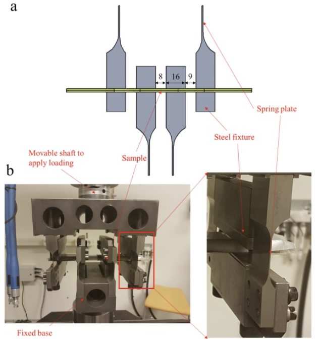
Fig. 3. (a) Schematic of four-point reversed bending set-up used in this study. Dimensions in mm. (b) Picture of the bending fatigue test set-up. The specimen was fixed by four fixtures, where two outer fixtures were connected to upper moveable shaft for applying the loading. The two internal fixtures were connected to the fixed base in the bottom. Between the fixture and the shaft/base were thin steel spring to ensure that the specimens can bend flexibly. To show the details more clearly, the distance between each fixture shown in the picture is larger than the actual distances used in this study.