This article introduces the paper "Effect of Heat Sink Structure on Cooling Performance of LED Bulb".
1. Overview:
- Title: Effect of Heat Sink Structure on Cooling Performance of LED Bulb
- Authors: T. Kobayashi, S. Ishikawa, R. Hashimoto, H. Kanematsu, and Y. Utsumi
- Year: 2014
- Publication: The 3rd International Conference on Design Engineering and Science, ICDES 2014
- Keywords: light emitting diode bulb, heat sink, heat transfer, finite element method, temperature distribution
2. Research Background:
LEDs are increasingly used due to their long lifespan and high efficiency. However, LEDs are point heat sources, leading to localized temperature increases in the surrounding polymer molding material, peripheral devices, and the LED element itself. This temperature rise negatively impacts luminous efficiency (a 5-8% decrease for every 10°C increase), drastically reduces lifespan (halving for every 10°C rise), and causes issues like material degradation and insulation failure. Prior research often simplified geometrical models, focusing solely on convective heat transfer and lacking experimental validation.
3. Research Objectives and Questions:
- Objective: To optimize the heat sink structure of an LED bulb to minimize LED temperature and improve performance, providing design guidelines.
- Key Research Question: How do various parameters (heat sink shape, material, dimensions) affect LED temperature? What is the optimal heat sink design?
- Hypothesis: Systematic variation of heat sink parameters in a finite element analysis (FEA) considering convection and radiation will yield optimal design guidelines.
4. Methodology:
- Research Design: Three-dimensional unsteady-state heat transfer analysis using the finite element method (FEM), incorporating convection and radiation. Design of Experiments (DOE) using an L18 orthogonal array.
- Data Collection: Temperature distribution data obtained from FEM analysis and experimental measurements using thermocouples and a thermal imager.
- Analysis Methods: Regression analysis to quantify the influence of each parameter.
- Subjects and Scope: A 6W LED bulb (with 3 or 6 LED elements), exploring various heat sink designs (presence/absence of outer cylinder, number of fins, fin height, thickness, material, etc.).
5. Main Findings:
- Key Findings: The optimal heat sink design (based on FEM analysis) features an open-type structure (no outer cylinder), 24 copper fins (15mm height), and 6 LED chips, resulting in a maximum temperature of 38°C. The worst-case scenario resulted in a maximum temperature of 242°C. Experimental results showed good agreement with FEM predictions, though experimental temperatures were slightly higher (approximately 2°C).
- Statistical/Qualitative Analysis: Analysis revealed the significant influence of several parameters on maximum temperature: presence/absence of outer cylinder, number of fins, number of LED chips, fin height, substrate thickness, material, and inner temperature. A regression equation was derived to predict maximum temperature (Tmax=147.2-6.34Qa-1.29Qb-1.81Qc+0.1Qd-1.42Qe-16.14Qf+0.80Qg-4.14Qh). The influence factors indicated that material, fin number, LED chip number, and fin height were most influential.
- Data Interpretation: Experimental validation confirmed the FEM analysis within an acceptable margin of error.
- Figures and Tables: The paper included figures illustrating basic models, calculation model examples, comparisons of FEM and regression analysis results, influence factors, optimal, worst, and reasonable models, and tables detailing calculation conditions, the orthogonal array, material properties, parameter and calculated results for each model, and a comparison of measured and calculated temperatures.
- Figure 1: Basic models used for analysis
- Figure 2: Examples of calculation model
- Figure 3: Comparison between the results of regression analysis and finite element method analysis
- Figure 4: Influence factor of each parameter on the maximum temperature (heat transfer and radiation)
- Figure 5: Best model
- Figure 6: Worst model
- Figure 7: Reasonable model
- Figure 8: Influence factor of each parameter on the maximum temperature (without radiation)
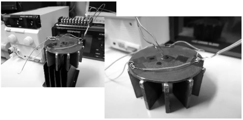
- Figure 9: A model proto-typed for experiment

6. Conclusion and Discussion:
The FEM analysis and experimental results demonstrated a strong correlation, validating the methodology. While the optimal design showed superior cooling performance, practical considerations (manufacturing cost, maintenance, design simplicity) should guide the selection of a suitable model. A compromise “reasonable” model was proposed that balanced performance and practicality.
7. Future Research:
Further research could investigate a broader range of LED chip sizes and power levels. Additional analysis under varied environmental conditions (convective heat transfer coefficients) would enhance the generality of the findings. Further work is needed to develop comprehensive design guidelines readily applicable to real-world product design.
8. References Summary:
The paper cited several references focusing on LED technology, thermal design, and simulation methods. [1] Nozawa T. (2008). Nikkei Electronics.
[2] Office of Energy Efficiency and Renewable Energy, U.S. Department of Energy. (2011).
[3] Qin, Y. Y., & Ron Hui, S. Y. (2010).
[4] Chou, H., & Yang, T. (2007).
[5] Osawa, S., Izumi, M., & Sakamoto, S. (2010).
[6] Kobayashi, T., Sakate, Y., Hashimoto, R., Takashina, T., Kanematsu, H., Mizuta, K., & Utsumi, Y. (2012).
[7] Cybernet systems co., ltd. (2010). ANSYS.
Copyright:
This summary is based on the research paper: "Effect of Heat Sink Structure on Cooling Performance of LED Bulb" by T. Kobayashi et al.
Unauthorized commercial use is prohibited.
Copyright © 2025 CASTMAN. All rights reserved.