본 소개 자료는 "Materials (MDPI)"에서 출판된 "[Influence of Salt Support Structures on Material Jetted Aluminum Parts]" 논문을 기반으로 합니다.
![Figure 1. Phase diagram of KCl and NaCl according to Bale et al. [20]. The melting temperature of the eutectic mixture is 657 °C. There is a solid solution miscibility gap up to temperatures of approximately 500 °C [19].](https://castman.co.kr/wp-content/uploads/image-2170.webp)
1. 개요:
- 제목: Influence of Salt Support Structures on Material Jetted Aluminum Parts (재료 분사 방식 알루미늄 부품에 대한 염 서포트 구조의 영향)
- 저자: Benedikt Kirchebner, Maximilian Ploetz, Christoph Rehekampff, Philipp Lechner and Wolfram Volk
- 발행 연도: 2021
- 발행 학술지/학회: Materials (MDPI)
- 키워드: additive manufacturing (적층 제조); material jetting (재료 분사); support structure (서포트 구조)
2. 초록:
대부분의 금속 적층 제조 공정과 마찬가지로, 재료 분사(Material Jetting) 공정은 완전한 3D 구현 능력을 얻기 위해 서포트 구조가 필요합니다. 서포트 구조는 후속 작업에서 제거되어야 하며, 이는 비용을 증가시키고 제조 공정을 지연시킵니다. 이 문제에 대한 한 가지 접근 방식은 빠르고 경제적인 서포트 제거를 가능하게 하는 염(salt)으로 만들어진 수용성 서포트 구조를 사용하는 것입니다. 본 논문에서는 재료 분사 방식 알루미늄 부품에 대한 염 서포트 구조의 영향을 분석합니다. 염은 용융 상태로 적용되며, 용융 염은 일반적으로 부식성이 있기 때문에 서포트와 빌드 재료 간의 상호 작용을 조사하는 것이 중요합니다. 염의 다른 특징적인 속성으로는 높은 용융 온도와 낮은 열전도율이 있으며, 이는 이미 프린트된 구조물의 재용융을 유발할 수 있고 낮은 냉각 속도로 인해 염 위에 프린트되는 알루미늄의 미세 구조에 영향을 미칠 수 있습니다. 세 가지 다른 샘플 형상을 광학 현미경, 공초점 레이저 스캐닝 현미경, 에너지 분산형 X선 분광법 및 미세 경도 시험을 사용하여 조사했습니다. 결과는 재용융, 미세 경도 및 화학 반응과 관련하여 공정에 뚜렷한 영향이 없음을 나타냅니다. 그러나 염 위에 프린트된 알루미늄에서는 더 큰 덴드라이트 가지 간격(dendrite arm spacing)이 관찰됩니다.
3. 서론:
재료 분사(Material Jetting, MJT) 적층 제조 공정은 빌드 재료의 제어된 액적 단위 증착을 기반으로 합니다. 상업적으로 이용 가능한 MJT 프린터는 주로 포토폴리머와 왁스 가공에 중점을 둡니다[1]. 그러나 용융 금속[2] 및 용융 염[3]의 가공 또한 시연되었습니다. 금속 부품은 폴리머, 왁스, 염과 비교하여 높은 기계적 강도를 제공하기 때문에 산업 응용 분야에서 특히 중요합니다. 적층 제조의 가장 큰 장점은 아마도 설계 자유도일 것입니다. Jayabal 등[4], Sukhotskiy 등[5], Zhang 등[6]이 보여준 바와 같이, 복잡한 형상과 특정 각도까지 기울어진 구조물은 금속 MJT로 프린트할 수 있습니다. 그러나 완전한 3D 구현 능력을 위해서는 대부분의 적층 공정에 어떤 형태의 서포트 구조가 필요합니다. 이러한 서포트 구조의 단점은 프린팅 공정 후에 제거해야 한다는 것이며, 이는 비용을 증가시키고 가공 체인을 느리게 만듭니다[7]. 따라서 서포트 구조의 필요성은 부품의 방향을 변경하는 등 가능한 한 최소화되어야 합니다.
서포트 구조는 종종 부품과 동일한 재료로 만들어집니다. 이 경우, Hussein 등[8]이 보여준 것처럼, 기계 가공에 필요한 노력을 줄이는 낮은 부피 분율을 가진 미세 구조를 사용하여 서포트 구조를 최적화할 수 있습니다. 또 다른 접근 방식은 부품과 다른 재료로 서포트 구조를 만드는 것인데, 이는 예를 들어 용해를 통해 더 쉽게 제거할 수 있습니다[9]. 수용성 재료는 이미 주조 산업에서 고압 다이캐스팅용 코어를 만드는 데 사용됩니다[10]. 순수 염[11] 외에도 염 혼합물로 만든 주조 코어에 대한 연구도 수행되었습니다[12]. 특히 액상으로 염을 다룰 때, 즉 코어 주조 시 금속에 대한 용융 염의 부식성을 고려해야 합니다[13]. 많은 염의 또 다른 특징은 낮은 열전도율입니다[14]. 이러한 모든 측면은 용융 염 가공을 주조 산업에서 적층 제조로 이전할 때 고려되어야 합니다.
4. 연구 요약:
연구 주제의 배경:
금속의 재료 분사(MJT) 방식은 복잡한 형상을 만들기 위해 서포트 구조가 필요하지만, 이를 제거하는 과정에서 비용과 시간이 추가됩니다. 수용성 염은 기존 금속 서포트보다 빠르고 경제적인 제거가 가능한 잠재적 해결책을 제공합니다.
이전 연구 현황:
이전 연구에서는 AlSi12(a)의 MJT 공정[16]을 시연했으며, MJT를 통한 염 가공을 탐구하여 가공성 때문에 KCl-NaCl을 적합한 후보로 식별했습니다[3]. 수용성 염 코어의 사용은 다이캐스팅에서 알려져 있습니다[10]. 용융 염의 잠재적 문제점으로는 부식성[13]과 낮은 열전도율[14]이 있으며, 이는 빌드 재료에 영향을 미칠 수 있습니다. 적층 제조에서 이종 재료 간의 계면 연구는 존재합니다[15].
연구 목적:
본 연구는 "염을 서포트 재료로 도입하는 것이 우리의 MJT 공정에 어떤 영향을 미칠 것인가?"라는 연구 질문에 답하는 것을 목표로 했습니다. 구체적으로, 재료 분사 방식 AlSi12(a) 알루미늄 부품의 서포트 구조로 공융 KCl-NaCl 염 혼합물을 사용할 때 발생할 수 있는 잠재적 부정적 영향을 조사했습니다. 조사는 다음 사항을 식별하는 데 중점을 두었습니다:
- 알루미늄-염 계면에서의 부식의 시각적 징후.
- 용융 염의 열로 인한 표면 구조 변화(재용융).
- 세척 후 알루미늄 표면의 염 잔류물.
- 염 위에서의 잠재적으로 느린 냉각으로 인한 알루미늄 미세 구조 변화(덴드라이트 가지 간격).
- 변경된 미세 구조 또는 열 이력으로 인한 미세 경도 변화.
핵심 연구 내용:
연구의 핵심은 세 가지 다른 샘플 형상(AS-샘플: 염 위에 알루미늄 프린트; SA-샘플: 알루미늄 위에 염 프린트; UL-샘플: 염 서포트와 프린팅 플레이트 위에 부분적으로 알루미늄 프린트)을 빌드 재료로 AlSi12(a)를 사용하고 서포트 재료로 공융 KCl-NaCl 혼합물을 사용하여 프린트하는 것이었습니다. 알루미늄과 염 서포트 구조 간의 상호 작용을 평가하기 위해 광학 현미경, 공초점 레이저 스캐닝 현미경(CLSM), 에너지 분산형 X선 분광법(EDX) 및 미세 경도 시험을 사용하여 계면 및 벌크 특성을 특성화했습니다.
5. 연구 방법론
연구 설계:
실험적 접근 방식을 사용하여, 다양한 조건에서 프린트된 AlSi12(a) 알루미늄 구조를 비교했습니다: 고화된 염(KCl-NaCl) 서포트 구조 위에 프린트된 알루미늄(AS-샘플), 고화된 알루미늄 위에 프린트된 염(SA-샘플), 그리고 염 서포트와 프린팅 플레이트 위에 부분적으로 프린트된 알루미늄(UL-샘플). 이를 통해 다양한 접촉 시나리오(고체 염 위의 용융 Al, 고체 Al 위의 용융 염)에서의 상호 작용을 조사하고 기준 조건(프린팅 플레이트 위의 Al)과 비교할 수 있었습니다.
데이터 수집 및 분석 방법:
- 재료 프린팅: 샘플은 알루미늄과 염을 위한 교체 가능한 프린트 헤드가 있는 공압 작동식 주문형 액적(drop-on-demand) MJT 테스트 스탠드를 사용하여 질소 퍼지 챔버 내에서 제작되었습니다[3, 16]. 빌드 재료는 AlSi12(a) 와이어였고, 서포트는 공융 KCl-NaCl 혼합물이었습니다.
- 샘플 준비: 서포트 구조는 수동으로 제거하고 초음파 세척기를 사용하여 증류수에서 용해시킨 후 에탄올 세척 및 건조 과정을 거쳤습니다. 단면 분석(UL-샘플)을 위해 샘플을 에폭시 수지에 냉간 마운팅하고, 연삭, 연마한 후 2% 수산화나트륨(NaOH) 수용액 또는 NaOH 처리 후 알칼리성 과망간산칼륨 용액[22]을 이용한 이중 에칭으로 에칭했습니다.
- 분석 기법:
- 광학 현미경: Zeiss Axioplan 2를 사용하여 UL-샘플의 에칭된 단면을 검사하여 미세 구조(덴드라이트 가지 간격) 및 부식 징후를 확인했습니다.
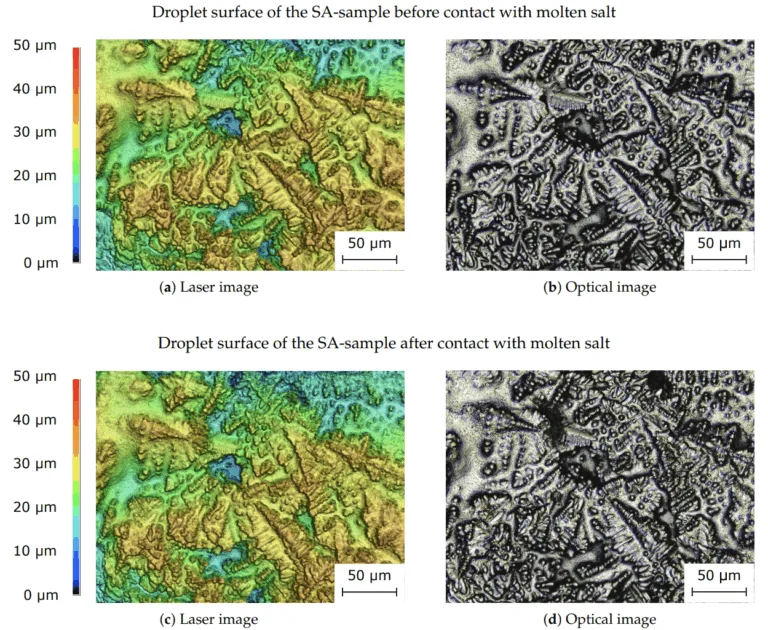
- 공초점 레이저 스캐닝 현미경(CLSM): Keyence VK-X100을 사용하여 SA-샘플의 염 증착 전후 3D 표면 형상을 분석하여 잠재적인 재용융을 감지했습니다.
- 에너지 분산형 X선 분광법(EDX): Oxford Instruments 검출기가 장착된 JEOL JSM-7500F SEM을 사용하여 SA, AS 및 UL 샘플에 대해 수행되었으며(10kV 가속 전압), 계면/표면에서의 원소 조성 및 잠재적 염 잔류물 또는 반응 생성물을 식별했습니다.
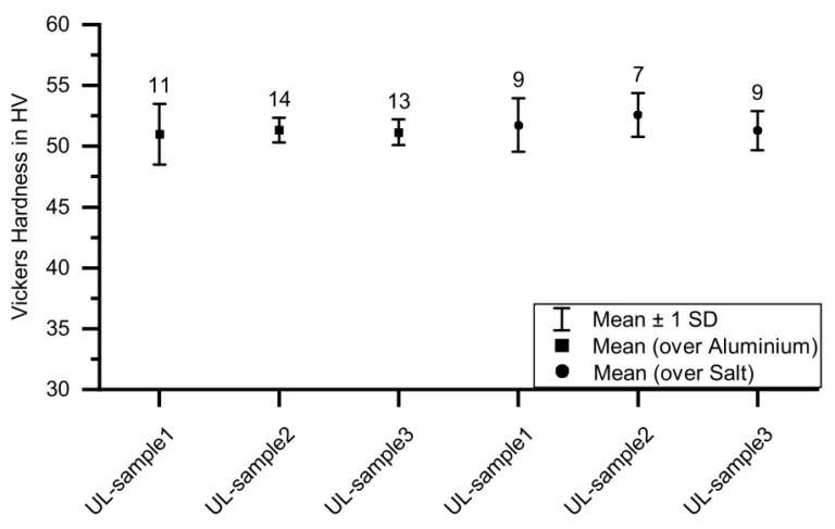
- 미세 경도 시험: LECO LM100AT 시험기를 사용하여 UL-샘플의 연마된 단면에 대해 비커스 미세 경도 시험(HV0.025)을 수행했으며, 측정 그리드 배치는 DIN EN ISO 6507-1 지침을 따랐습니다.
연구 주제 및 범위:
본 연구는 재료 분사 방식 AlSi12(a) 알루미늄 합금과 공융 KCl-NaCl 수용성 염 서포트 구조 간의 상호 작용에 구체적으로 초점을 맞췄습니다. 범위에는 잠재적 부식, 열 효과(재용융, 덴드라이트 가지 간격과 같은 미세 구조 변화), 화학적 잔류물 및 빌드 재료와 서포트 재료 간의 계면 또는 그 근처에서의 결과적인 기계적 특성 변화(미세 경도) 조사가 포함되었습니다.
6. 주요 결과:
주요 결과:
- 부식: 에칭된 UL-샘플 단면의 광학 현미경 관찰 결과, 알루미늄이 용융 염과 접촉했던 알루미늄-염 계면에서 부식의 명확한 시각적 징후는 발견되지 않았습니다.
- 재용융: 용융 염과 접촉 전후의 알루미늄 표면(SA-샘플)에 대한 공초점 레이저 스캐닝 현미경 분석 결과, 표면 구조(덴드라이트 특징)에 유의미한 변화가 없어 알루미늄의 상당한 재용융이 발생하지 않았음을 나타냅니다.
- 미세 구조: 광학 현미경 관찰 결과, 염 서포트 구조 위에 프린트된 알루미늄의 덴드라이트 가지 간격이 알루미늄 기판/프린팅 플레이트 위에 직접 프린트된 알루미늄(평균 4.04 µm)에 비해 더 컸습니다(세 UL-샘플 평균 4.68 µm). 이는 알루미늄에 비해 염의 낮은 열전도율로 인해 염 위에서 더 느린 응고가 일어났음을 시사합니다.
- 화학적 상호작용/잔류물: EDX 분석 결과, 샘플 표면에서 주로 Al, Si, C, O가 검출되었습니다. 합금 원소인 Fe도 검출되었습니다. AS-샘플의 한 측정에서 약한 염소(Cl) 신호가 관찰되었으며, 이는 세척 후 미량의 염 잔류물을 나타낼 수 있지만, 광학 현미경 결과는 부식이 원인임을 뒷받침하지 않았습니다. 염 혼합물에서 유래한 나트륨(Na)과 칼륨(K)은 어떤 EDX 스펙트럼에서도 검출되지 않았습니다.
- 미세 경도: UL-샘플에 대한 비커스 미세 경도 시험(HV0.025) 결과, 관찰된 덴드라이트 가지 간격의 차이에도 불구하고 알루미늄 위에 프린트된 영역(평균 51.0-52.6 HV0.025)과 염 서포트 구조 위에 프린트된 영역(평균 51.0-52.6 HV0.025) 사이에 유의미한 차이나 구배는 나타나지 않았습니다.
그림 이름 목록:
- Figure 1. Phase diagram of KCl and NaCl according to Bale et al. [20]. The melting temperature of the eutectic mixture is 657 °C. There is a solid solution miscibility gap up to temperatures of approximately 500 °C [19].
- Figure 2. Schematic representation of the SA-sample (a), AS-sample (b) and UL-sample (c). Dark gray areas designate the aluminum part, light gray areas the support structure and black areas the heated nickel-plated steel printing plate.
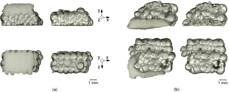
- Figure 3. SA-sample (a) and AS-sample (b) with salt support structure and after support removal. The top row shows the samples viewed from the side, the bottom row viewed from above.
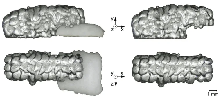
- Figure 4. UL-sample with salt support structure and after support removal. The top row shows the sample viewed from the side, the bottom row viewed from above.
- Figure 5. Flow chart of the experimental procedure. Three sample geometries (SA-sample, AS-sample and UL-sample) are printed out of aluminum and salt via Material Jetting (MJT). […] Optical microscopy, energy-dispersive X-ray spectroscopy and micro-hardness testing are performed.
- Figure 6. Measuring grid for micro-hardness measurement. The measuring points are located in the center of the sample in the vertical direction so that the hardness measurement is not distorted by possible edge influences. […] The distance between the measuring points is 0.5 mm.
- Figure 7. Cross-sectional area of UL-sample etched with two percent aqueous sodium hydroxide solution. The images above the cross-sectional area show the detailed views of the material microstructure of the sample area above the aluminum (left side) and above the salt support structure (right side). In the area above the salt support structure, a coarser dendrite structure can be observed.
- Figure 8. Dendrite arm spacing in the aluminum part (UL-sample). The squares show the dendrite arm spacing in the area above the aluminum and the circles show the dendrite arm spacing above the salt support structure. […] a larger dendrite arm spacing tends to be observed in the area above the salt support structure.
- Figure 9. Cross-sectional area of UL-sample etched with two percent aqueous sodium hydroxide solution and alkaline potassium permanganate solution according to Weck et al. [22]. […] A coarser dendrite structure can be seen in the area above the salt support structure.
- Figure 10. Three spectra for the SA-sample, superimposed in a single diagram. Aluminum, silicon, carbon and oxygen were detected. The three spectra differ in peak height, the peak positions do not change.
- Figure 11. Three spectra for the AS-sample, superimposed in a single diagram. Aluminum, silicon, carbon, oxygen, iron and chlorine were detected. […] One of the three spectra shows a weak chlorine signal with all peaks < 150 counts.
- Figure 12. Three spectra for the UL-sample, superimposed in a single diagram. Aluminum, silicon, carbon and oxygen were detected. The three spectra differ in peak height, the peak positions do not change.
- Figure 13. Surface of the SA-sample analyzed with the confocal laser scanning microscope. The top images show the sample’s surface before coming into contact with molten salt and the bottom two images show the surface after molten salt contact. […] No significant change in the surface can be seen. […]
- Figure 14. Vickers micro-hardness values in the aluminum part (UL-sample). The squares show the micro-hardness values in the area above the aluminum and the circles show the micro-hardness values above the salt support structure. […] no significant influence of the salt support structure on the micro-hardness occurring in the aluminum can be determined.
7. 결론:
본 연구는 재료 분사 방식 AlSi12(a) 알루미늄 부품의 수용성 서포트 구조로 KCl-NaCl 염 혼합물을 사용하는 효과를 조사했습니다. 광학 현미경, CLSM, EDX 및 미세 경도 시험을 통한 분석 결과, 공정이나 최종 부품 특성에 뚜렷한 부정적 영향은 발견되지 않았습니다. 구체적으로, 알루미늄-염 계면에서 부식의 명확한 시각적 징후가 없었고, 용융 염과의 접촉 시 알루미늄 표면의 유의미한 재용융이 없었으며, 염 위에 프린트된 알루미늄과 알루미늄 위에 프린트된 알루미늄 간의 미세 경도에 유의미한 변화가 없었습니다. 관찰된 미미한 효과는 염 위에 프린트된 알루미늄에서 더 거친 덴드라이트 구조였으며, 이는 염의 낮은 열전도율로 인한 느린 냉각 속도 때문으로 여겨집니다. EDX는 한 경우에 미량의 염소 잔류 가능성을 감지했지만, 유의미한 화학 반응 생성물은 없었습니다. 결과는 KCl-NaCl이 특히 단순한 형상에 대해 알루미늄의 MJT를 위한 잠재적으로 적합한 수용성 서포트 재료임을 시사합니다. 그러나 더 복잡한 형상과 더 큰 서포트 구조에서의 성능을 평가하기 위해서는 추가 연구가 필요합니다.
8. 참고 문헌:
- [1] Wohlers, T.T.; Campbell, I.; Diegel, O.; Huff, R.; Kowen, J. Wohlers Report 2021: 3D Printing and Additive Manufacturing Global State of the Industry; Wohlers Associates: Fort Collins, CO, USA, 2021.
- [2] Liu, Q.; Orme, M. On precision droplet-based net-form manufacturing technology. Proc. Inst. Mech. Eng. Part B J. Eng. Manuf. 2001, 215, 1333–1355. [CrossRef]
- [3] Kirchebner, B.; Rehekampff, C.; Tröndle, M.; Lechner, P.; Volk, W. Analysis of salts for use as support structure in metal material jetting. Prod. Eng. 2021. [CrossRef]
- [4] Jayabal, D.K.K.; Zope, K.; Cormier, D. Fabrication of support-less engineered lattice structures via jetting of molten aluminium droplets. In Proceedings of the 29th Annual International Solid Freeform Fabrication Symposium—An Additive Manufacturing Conference, Austin, TX, USA, 13–15 August 2018; Volume 1, pp. 757–764.
- [5] Sukhotskiy, V.; Karampelas, I.H.; Garg, G.; Verma, A.; Tong, M.; Vader, S.; Vader, Z.; Furlani, E.P. Magnetohydrodynamic Drop-on-Demand Liquid Metal 3D Printing. In Proceedings of the 28th Annual International Solid Freeform Fabrication Symposium—An Additive Manufacturing Conference, Austin, TX, USA, 7–9 August 2017; Volume 1, pp. 1806–1811.
- [6] Zhang, D.; Qi, L.; Luo, J.; Yi, H.; Hou, X. Direct fabrication of unsupported inclined aluminum pillars based on uniform micro droplets deposition. Int. J. Mach. Tools Manuf. 2017, 116, 18–24. [CrossRef]
- [7] Jiang, J.; Xu, X.; Stringer, J. Support Structures for Additive Manufacturing: A Review. J. Manuf. Mater. Process. 2018, 2, 64. [CrossRef]
- [8] Hussein, A.; Hao, L.; Yan, C.; Everson, R.; Young, P. Advanced lattice support structures for metal additive manufacturing. J. Mater. Process. Technol. 2013, 213, 1019–1026. [CrossRef]
- [9] Duran, C.; Subbian, V.; Giovanetti, M.T.; Simkins, J.R.; Beyette Jr, F.R. Experimental desktop 3D printing using dual extrusion and water-soluble polyvinyl alcohol. Rapid Prototyp. J. 2015, 21, 528–534. [CrossRef]
- [10] Huang, R.; Zhang, B. Study on the Composition and Properties of Salt Cores for Zinc Alloy Die Casting. Int. J. Met. 2017, 11, 440–447. [CrossRef]
- [11] Jelínek, P.; Adámková, E.; Mikšovský, F.; Beˇno, J. Advances inTechnology of Soluble Coresfor Die Castings. Arch. Foundry Eng. 2015, 15, 29–34. [CrossRef]
- [12] Yaokawa, J.; Miura, D.; Anzai, K.; Yamada, Y.; Yoshii, H. Strength of Salt Core Composed of Alkali Carbonate and Alkali Chloride Mixtures Made by Casting Technique. Mater. Trans. 2007, 48, 1034–1041. [CrossRef]
- [13] Ozeryanaya, I.N. Corrosion of metals by molten salts in heat-treatment processes. Metal Sci. Heat Treat. 1985, 27, 184–188. [CrossRef]
- [14] Janz, G.J. Molten Salts Handbook; Elsevier Science: Burlington, VT, USA, 1967.
- [15] Shiran, M.K.G.; Khalaj, G.; Pouraliakbar, H.; Jandaghi, M.; Bakhtiari, H.; Shirazi, M. Effects of heat treatment on the intermetallic compounds and mechanical properties of the stainless steel 321–aluminum 1230 explosive-welding interface. Int. J. Miner. Metall. Mater. 2017, 24, 1267–1277. [CrossRef]
- [16] Himmel, B.; Rumschoettel, D.; Volk, W. Tensile properties of aluminium 4047A built in droplet-based metal printing. Rapid Prototyp. J. 2019, 25, 427–432. [CrossRef]
- [17] Mills, K.C. Recommended Values of Thermophysical Properties for Selected Commercial Alloys; Woodhead: Cambridge, UK, 2002.
- [18] Barrett, W.T.; Wallace, W.E. Studies of NaCl-KCl Solid Solutions. I. Heats of Formation, Lattice Spacings, Densities, Schottky Defects and Mutual Solubilities 1,2. J. Am. Chem. Soc. 1954, 76, 366–369. [CrossRef]
- [19] Sergeev, D.; Kobertz, D.; Müller, M. Thermodynamics of the NaCl–KCl system. Thermochim. Acta 2015, 606, 25–33. [CrossRef]
- [20] Bale, C.W.; Bélisle, E.; Chartrand, P.; Decterov, S.A.; Eriksson, G.; Gheribi, A.E.; Hack, K.; Jung, I.H.; Kang, Y.B.; Melançon, J.; et al. FactSage Thermochemical Software and Databases—2010–2016. Calphad 2016, 35–53. [CrossRef]
- [21] Ansell, T.Y. Current Status of Liquid Metal Printing. J. Manuf. Mater. Process. 2021, 5, 31. [CrossRef]
- [22] Weck, E.; Leistner, E. Metallographische Anleitung zum Farbätzen nach dem Tauchverfahren: = Metallographic Instructions for Colour Etching by Immersion; Vol. Bd. 77; Fachbuchreihe Schweisstechnik, Dt. Verl. für Schweisstechnik DVS-Verl.: Düsseldorf, Germany, 1986.
- [23] Goldstein, J.I.; Newbury, D.E.; Michael, J.R.; Ritchie, N.W.; Scott, J.H.J.; Joy, D.C. Scanning Electron Microscopy and X-ray Microanalysis, 4th ed.; Springer: New York, NY, USA, 2018. [CrossRef]
- [24] Jenkins, R.; Manne, R.; Robin, R.; Senemaud, C. IUPAC—Nomenclature system for x-ray spectroscopy. X-ray Spectrom. 1991, 20, 149–155. [CrossRef]
- [25] Bearden, J.A. X-ray Wavelengths. Rev. Mod. Phys. 1967, 39, 78–124. [CrossRef]
9. 저작권:
- 본 자료는 "Benedikt Kirchebner, Maximilian Ploetz, Christoph Rehekampff, Philipp Lechner and Wolfram Volk"의 논문입니다. "Influence of Salt Support Structures on Material Jetted Aluminum Parts"를 기반으로 합니다.
- 논문 출처: https://doi.org/10.3390/ma14154072
본 자료는 상기 논문을 바탕으로 요약된 자료이며, 상업적 목적의 무단 사용을 금지합니다.
Copyright © 2025 CASTMAN. All rights reserved.


![Figure 9. Cross-sectional area of UL-sample etched with two percent aqueous sodium hydroxide solution and alkaline potassium permanganate solution according to Weck et al. [22]. [...] A coarser dendrite structure can be seen in the area above the salt support structure.](https://castman.co.kr/wp-content/uploads/image-2174-768x538.webp)

