1. 개요:
- 제목: 고성능, 저충전량 열교환기 설계 및 제조 (Design and Manufacturing of High Performance, Reduced Charge Heat Exchangers)
- 저자: Reinhard Radermacher 외
- 발행 연도: 2023
- 발행 학술지/학회: 미국 에너지부 (Department of Energy) 최종 기술 보고서 (Final Technical Report)
- Keywords: 열교환기, 최적화, 다중 물리 해석, 첨가제 제조, 비원형 튜브, 저GWP 냉매
2. 연구 배경:
주거 및 상업용 건물의 에너지 소비량 중 냉난방 및 냉동 시스템(HVAC&R)이 차지하는 비중이 상당하며, 냉매 충전량 감소를 통한 온실가스 배출 저감이 중요한 과제로 떠오르고 있다. 기존의 원형 튜브 및 핀을 사용하는 열교환기는 성능 향상에 한계가 있으며, 냉매 충전량 감소를 위해 더욱 소형화된 설계가 필요하다. 따라서, 냉매 충전량 감소와 동시에 성능 향상을 달성할 수 있는 차세대 열교환기 개발이 필수적이다. 기존 연구는 주로 단일 물리(열-유체) 해석 및 형상 최적화에 집중해왔으며, 제조의 어려움과 운영상의 문제점(유동 불균형, 오염, 발진 및 진동) 등 실제 상용화에 대한 고려가 부족했다.
3. 연구 목적 및 연구 질문:
- 연구 목적: 냉매 충전량을 30% 감소시키면서 기존 시스템 대비 25% 더 가볍고 25% 더 소형화된 고성능 공기-냉매 열교환기를 설계 및 제조하는 것.
- 핵심 연구 질문:
- 비원형 튜브를 사용한 열교환기의 열-유체 성능, 기계적 강도, 소음 성능 및 내구성을 동시에 고려한 다중 물리 최적화 프레임워크를 어떻게 개발할 수 있는가?
- 비원형 튜브 제조 및 튜브-헤더 통합을 위한 새로운 제조 기술을 어떻게 개발할 수 있는가?
- 개발된 열교환기의 성능을 실험적으로 검증하고 실제 HVAC&R 시스템 적용 가능성을 평가할 수 있는가?
- 연구 가설: 비원형 튜브를 사용하고 다중 물리 최적화를 적용하면 냉매 충전량 감소 및 성능 향상을 동시에 달성할 수 있다.
4. 연구 방법론:
- 연구 설계: 다중 물리 최적화 프레임워크를 개발하여 비원형 튜브를 이용한 열교환기를 설계하고, 새로운 제조 기술을 개발하여 시제품을 제작하고 실험적으로 검증하는 과정으로 설계되었다.
- 데이터 수집 방법: CFD (Computational Fluid Dynamics), FEA (Finite Element Analysis), 실험적 측정 (Component-level & System-level)
- 분석 방법: 다중 물리 최적화 프레임워크 (AAO, MOGA), 그리드 수렴 지수 (GCI), 메타 모델 (Kriging), 통계적 유의성 검정
- 연구 대상 및 범위: 다양한 냉매 (R410A, R32, R454B, R290, 초임계 이산화탄소) 및 응용 분야 (에어컨, 히트펌프, 가스 냉각기)를 포함하여 광범위하게 열교환기 최적화를 수행했다. 시제품 제작 및 실험 검증을 위해 구리 및 알루미늄 소재를 사용하였으며, 첨가제 제조 방식도 고려되었다.
5. 주요 연구 결과:
- 새로운 다중 물리 최적화 프레임워크를 통해 냉매 충전량을 최대 40% 감소시키면서, 기존 열교환기 대비 열-유체 성능을 15% 이상 향상시키는 비원형 튜브 열교환기를 설계하였다.
- 기계적 강도 및 소음 성능에 대한 다중 물리 모델을 개발하고 검증하여, 제조 및 운영상의 문제점을 해결하였다.
- 비원형 튜브 제조를 위한 새로운 제조 기술을 개발하고 시제품 제작 및 실험적 검증을 수행하였다. 총 10개의 시제품을 제작하였으며, 그 중 9개는 기존 제조 방식을 활용하고 1개는 첨가제 제조 방식을 활용하였다.
- 시제품 성능 실험 결과, 시뮬레이션 결과와 ±10~20% 이내 오차로 일치하여, 제안된 프레임워크의 예측 정확도가 높음을 확인했다. 특히, 건조 조건에서의 성능 예측 정확도가 우수하였다. 습윤 조건에서는 냉매 유동 불균형 현상이 예상보다 심각하게 발생하여 시뮬레이션과 실험 결과의 차이가 발생하였으나, 열 부하 예측은 우수한 정확도를 보였다.
- Figure List
- Figure 1: Cost comparison of AM to Conventional manufacturing methods [134].
- Figure 2: Numerical optimization framework.
- Figure 3: (Left) Generic multi-pass tube-fin HX; (Right) Generic HX with shape-optimized tubes.
- Figure 4: HX depth wise cross-section: Design variable definitions for non-round tubes.
- Figure 5: HX pass configuration definition: (left) one fluid pass; (right) three fluid passes.
- Figure 6: Tube shape parameterization using NURBS.
- Figure 7: Automated FEA simulation flowchart.
- Figure 8: CFD domain, mesh, and boundary conditions.
- Figure 9: Dry air thermal-hydraulic performance metamodel verification & statistics.
- Figure 10: Aeroacoustics simulation CFD domain, boundary conditions, & mesh.
- Figure 11: Aeroacoustics performance correlation verification & statistics.
- Figure 12: Two-dimensional FEA model, boundary conditions, and mesh.
- Figure 13: Sample FEA model contours of von Mises stress.
- Figure 14: Boundary conditions for FEA simulations: (left) 2D and (right) 3D.
- Figure 15: Tube-level mechanical performance metamodel verification & statistics.
- Figure 16: Internal flow computational domain, boundary conditions, & sample mesh.
- Figure 17: Internal flow correlation development framework.
- Figure 18: CFD-based Nusselt number correlations verification and statistics.
- Figure 19: CFD-based friction factor correlation (full tube flow) verification and statistics.
- Figure 20: CFD-based friction factor correlation (developing flow) verification and statistics.
- Figure 21: CFD-based friction factor correlation (fully developed flow) verification and statistics.
- Figure 22: Dehumidification modeling methodology.
- Figure 23: Dehumidification model: (Left) Sample domain & boundary conditions; (Right) Sample mesh.
- Figure 24: CNTHX prototype.
- Figure 25: CNTHX experimental validation: (Left) Outlet dry bulb temperature; (Right) Outlet relative humidity.
- Figure 26: CNTHX dehumidification experimental validation: (Left) Outlet absolute humidity; (Right) Absolute humidity change.
- Figure 27: CNTHX dehumidification experimental validation: Sensible heat ratio.
- Figure 28: Lewis number parametric study results: (Top Left) Inlet air velocity (Reynolds number); (Top Right) Sensible heat transfer coefficient and mass transfer coefficient vs. inlet air velocity; (Bottom Left) Inlet relative humidity; (Bottom Right) Wall temperature.
- Figure 29: CFD-based Lewis number correlation validation & statistics.
- Figure 30: Optimal condenser designs colored by HX face area.
- Figure 31: Optimal condenser designs colored by HX core material volume.
- Figure 32: Optimal designs colored by HX core internal volume.
- Figure 33: Sample non-round tube HX produced by additive manufacturing [16].
- Figure 34: Single tube deformation test: (a) Experimental setup; (b) Numerical model.
- Figure 35: Single tube deformation test: (a) Experimental setup; (b) Numerical model.
- Figure 36: Single tube fatigue analysis: 4 tube designs using copper and aluminum.
- Figure 37: Single copper tube fatigue analysis: Contours of logarithmic life cycles.
- Figure 38: Single aluminum tube fatigue analysis: Contours of logarithmic life cycles.
- Figure 39: Header cross-sections: (Left) Square; (Middle) Half-Round; (Right) Round.
- Figure 40: Header stress distribution: (Left) Square; (Middle) Half-Round; (Right) Round.
- Figure 41: Header cross-sections: (Left) Square; (Middle) Half-Round; (Right) Round.
- Figure 42: Header stress distribution: (Left) Square; (Middle) Half-Round; (Right) Round.
- Figure 43: Header stress analysis for imperfect tube-solder joints.
- Figure 44: Solder stress distribution: (Left) Ideal fit vs. (Right) tube with 1.5° rotation.
- Figure 45: Plastic stress-strain curves: (Top) SAC 396; (Bottom) Copper.
- Figure 46: Solder plastic stress analysis: (Left) Plastic stress; (Right) Plastic strain.
- Figure 47: Schematic model of full tube-header assembly.
- Figure 48: Tube shapes of interest: (Top Left) Round; (Top Right) Ellipse; (Bottom) Non-Round Tube.
- Figure 49: Tube bundle stress contours: (Top Left) Round; (Top Right) Ellipse; (Bottom) Non-Round Tube.
- Figure 50: Tube bundle solder stress contours: (Top Left) Round; (Top Right) Ellipse; (Bottom) Non-Round Tube.
- Figure 51: Header stress contours: (Top Left) Round; (Top Right) Ellipse; (Bottom) Non-Round Tube.
- Figure 52: Life repeats vs. stress scale for different tube-header designs.
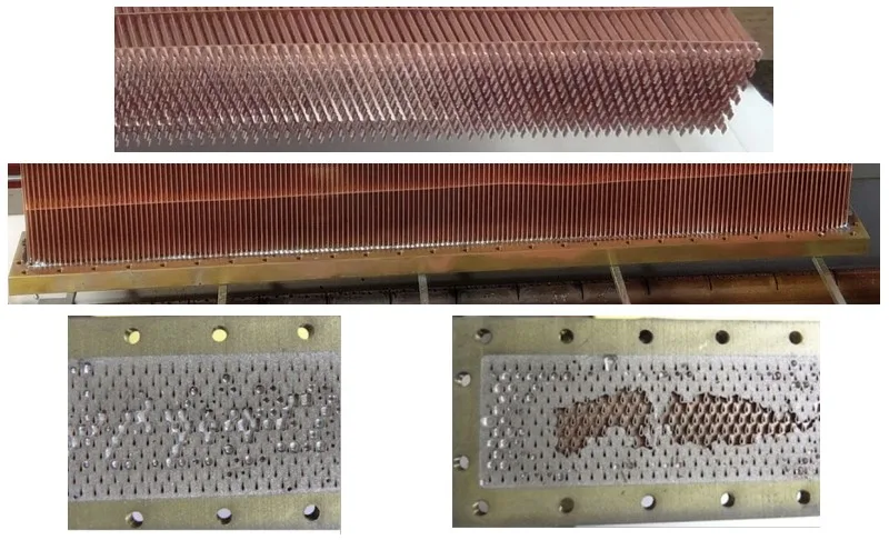
- Figure 53: Images of HX prototypes manufactured during the project.
- Figure 54: Non-round copper tube profile manufactured by drawing at STP.
- Figure 55: Non-round aluminum tube profile manufactured by extrusion at Brazeway.
- Figure 56: Non-round aluminum tube profile manufactured by extrusion at MetalKraft.
- Figure 57: HX Prototype 6-C3: (Left, Middle) Under construction; (Right) Pressure Test and Baffle location shown in red.
- Figure 58: HX Prototype 7-C4.
- Figure 59: HX Prototype 10-E2: (Top) Tube bundle; (Middle) Header after casting; (Bottom) Cut header with tube ends showing.
- Figure 60: Al 6063 tubes for all-aluminum HX prototype (one bundle shown).
- Figure 61: Aluminum HX assembly (~75% complete HX prototype shown).
- Figure 62: Aluminum HX pre-braze: (Left) Complete frame; (Right) Open tank ends.
- Figure 63: (Left) Full aluminum HX prototype before brazing at Diesel Radiator; (Right) Post-braze inspection revealed small gaps near tube trailing edges.
- Figure 64: Full aluminum HX prototype with multiple post-braze leaks.
- Figure 65: Adhesive leak repair test: (Left) Pre-curing; (Middle) Post-curing; (Right) Pressure test.
- Figure 66: Adhesive leak repair #1: (Top) Adhesive application; (Bottom) Leak test.
- Figure 67: Adhesive leak repair and pressure test #2 showing small leaks.
- Figure 68: Aluminum HX post-pressure test: (Top) Tank-header joint failure; (Bottom) Poor brazed interfaces between tube-header and header-tank.
- Figure 69: Schematic of closed loop wind tunnel.
- Figure 70: Schematic of pumped refrigerant loop.
- Figure 71: Blockage testing time lapse for (Top) 3-C1 & (Bottom): 6-C3.
- Figure 72: Prototype #1 energy balance: (Left) dry evaporator condition; (Right) dehumidifying condition.
- Figure 73: Prototype #1 validation: (Left) dry evaporator capacity & airside pressure drop; (Right) dehumidifying condition capacity.
- Figure 74: Prototype #1 wet condition experiment: (Left) air pressure drop; (Right); water droplets on HX tubes.
- Figure 75: Prototype #2 condenser experimental validation: (Left) energy balance; (Right).
- Figure 76: Component-level experimental validation summary: capacity.
- Figure 77: Component-level experimental validation summary: airside pressure drop.
- Figure 78: (a) Packaged A/C unit (b) Unit top view without top cover (c) Baseline tube-fin evaporator.
- Figure 79: Evaporator closed loop schematic and connection to packaged unit.
- Figure 80: Packaged unit test facility in environmental chamber.
- Figure 81: (a) NTHX-FSE overview including front and side views and CAD rendering; (b) Installation orientation in packaged unit.
- Figure 82: Modified NTHX-FSE: (Top) New inlet and outlet refrigerant ports; (Middle) Flow path; (Bottom) Installed in packaged unit.
- Figure 83: Schematic of system model.
6. 결론 및 논의:
본 연구는 냉매 충전량 감소 및 성능 향상을 동시에 달성할 수 있는 고성능 비원형 튜브 열교환기 설계 및 제조를 위한 새로운 다중 물리 최적화 프레임워크를 제시했다. 개발된 프레임워크는 다양한 냉매 및 응용 분야에 적용 가능하며, 기존 설계 방식에 비해 상당한 시간 및 비용 절감 효과를 제공한다. 실험 결과는 시뮬레이션 결과와 양호한 일치성을 보여, 프레임워크의 높은 예측 정확도를 입증하였다. 하지만, 습윤 조건에서 냉매 유동 불균형과 응축수 브리징 현상으로 인한 예측 오차가 발생한 점과 알루미늄 열교환기 제작 시 브레이징 과정에서 문제 발생으로 인한 시제품 제작 실패는 연구의 한계점으로 남는다.
7. 향후 후속 연구:
- 다양한 냉매 및 운전 조건에 대한 습윤 조건 성능 예측 정확도 향상 및 냉매 유동 불균형 해결을 위한 추가 연구
- 더욱 경제적이고 대량 생산 가능한 비원형 튜브 제조 기술 개발
- 헤더 설계 최적화 및 첨가제 제조 방식 활용에 대한 추가 연구
- 실제 HVAC&R 시스템에 적용하여 시스템 성능 향상 효과 및 상용화 가능성을 평가하는 연구
8. 참고문헌 요약:
- [1] J. Tancabel, V. Aute, and R. Radermacher, “Review of shape and topology optimization for design of air-to-refrigerant heat exchangers,” in 17th International Refrigeration & Air Conditioning Conference, West Lafayette, Indiana, USA, 2018.
- [2] E. Klein, J. Ling, V. Aute, and R. Radermacher, “A Review of Recent Advances in Additively Manufactured Heat Exchangers,” in 17th International Refrigeration and Air Conditioning Conference at Purdue, 2018.
- [3] J. Tancabel et al., “Multi-scale and multi-physics analysis, design optimization, and experimental validation of heat exchangers utilizing high performance, non-round tubes,” Appl Therm Eng, vol. 216, p. 118965, Nov. 2022, doi: 10.1016/j.applthermaleng.2022.118965.
- [4] J. Tancabel, “AN INTEGRATED, MULTI-PHYSICS ANALYSIS AND DESIGN OPTIMIZATION FRAMEWORK FOR AIR-TO-REFRIGERANT HEAT EXCHANGERS WITH SHAPE OPTIMIZED TUBES,” PhD, University of Maryland, College Park, College Park, MD, USA, 2022.
- [5] E. Klein, “DEVELOPMENT OF VARIABLE TUBE GEOMETRY HEAT EXCHANGERS USING ADJOINT METHOD WITH PERFORMANCE EVALUATION OF AN ADDITIVELY MANUFACTURED PROTOTYPE,” University of Maryland, College Park, College Park, MD USA, 2023.
- [6] United States Energy Information Administration, “Annual Energy Outlook 2022 with Projections to 2050,” 2022.
- [7] United States Department of Energy Office of Energy Efficiency and Renewable Energy, “Energy Conservation Standards for Residential Central Air Conditioners and Heat Pumps,” 2017.
- [8] United Nations Environment Ozone Secretariat, “Briefing Note on Ratification of the Kigali Amendment,” 2017.
- [9] W. M. Kays and A. L. London, Compact Heat Exchangers. New York: McGraw-Hill, 1984.
- [10] S. Paitoonsurikarn, N. Kasagi, and Y. Suzuki, “Optimal design of micro bare-tube heat exchanger,” Proceedings of Symposium on Engineering in the 21st century (SEE 2000), no. 3, 2000, Accessed: Oct. 06, 2022.
- [Online]. Available: https://citeseerx.ist.psu.edu/viewdoc/download?doi=10.1.1.17.1531&rep=rep1&ty pe=pdf
- [11] N. Saji, S. Nagai, K. Tsuchiya, H. Asakura, and M. Obata, “Development of a compact laminar flow heat exchanger with stainless steel micro-tubes,” Physica C Supercond, vol. 354, no. 1–4, pp. 148–151, May 2001, doi: 10.1016/S0921- 4534(01)00064-8.
- [12] N. Kasagi, Y. Suzuki, N. Shikazono, and T. Oku, “Optimal design and assessment of high performance micro bare-tube heat exchangers,” in 4th Int. Conf. on Compact Heat Exchangers and Enhancement Technologies for the Process Industries, 2003, pp. 241–246.
- [13] D. Bacellar, J. Ling, V. Aute, and R. Radermacher, “Multi-scale, multi-physics design of micro and mini bare tube heat exchangers using multi-objective approximation assisted optimization,” in 15th International Heat Transfer Conference, Tokyo, Japan, 2014.
- [14] D. Bacellar, V. Aute, Z. Huang, and R. Radermacher, “Novel airside heat transfer surface designs using an integrated multi-scale analysis with topology and shape optimization,” in 16th International Refrigeration and Air Conditioning Conference , West Lafayette, Indiana, USA, 2016.
- [15] H.-T. Chen, Y.-S. Lin, P.-C. Chen, and J.-R. Chang, “Numerical and experimental study of natural convection heat transfer characteristics for vertical plate fin and tube heat exchangers with various tube diameters,” Int J Heat Mass Transf, vol. 100, pp. 320–331, Sep. 2016, doi: 10.1016/j.ijheatmasstransfer.2016.04.039.
- [16] D. Bacellar, V. Aute, Z. Huang, and R. Radermacher, “Design optimization and validation of high-performance heat exchangers using approximation assisted optimization and additive manufacturing,” Sci Technol Built Environ, vol. 23, no. 6, pp. 896–911, Aug. 2017, doi: 10.1080/23744731.2017.1333877.
- [17] Z. Huang, “Development of a compact heat exchanger with bifurcated bare tubes,” PhD Dissertation, University of Maryland College Park, 2017.
- [18] Westphalen D., K. Roth, and J. Brodrick, “Heat Transfer Enhancement,” ASHRAE J, vol. 48, no. 4, pp. 68–70, 2006, Accessed: Jul. 19, 2022.
- [Online]. Available: https://www.proquest.com/docview/220462097?pqorigsite=gscholar&fromopenview=true#
- [19] K. Deb, Multi-objective optimization using evolutionary algorithms. New York: John Wiley & Sons, 2001.
- [20] T. W. Simpson, J. D. Peplinski, P. N. Koch, and J. K. Allen, “Metamodels for computer-based engineering design: survey and recommendations,” 2001.
- [21] G. Stanescu, A. J. Fowler, and A. Bejan, “The optimal spacing of cylinders in freestream cross-flow forced convection,” Int J Heat Mass Transf, vol. 39, no. 2, pp. 311–317, Jan. 1996, doi: 10.1016/0017-9310(95)00122-P.
- [22] M. F. Wright, “Plate-fin-and-tube condenser performance and design for a refrigerant R-410A air-conditioner ,” Master’s Thesis, Georgia Institute of Technology, 2000.
- [23] R. S. Matos, J. V. C. Vargas, T. A. Laursen, and F. E. M. Saboya, “Optimization study and heat transfer comparison of staggered circular and elliptic tubes in forced convection,” Int J Heat Mass Transf, vol. 44, no. 20, pp. 3953–3961, 2001.
- [24] K. A. Aspelund, “Optimization of plate-fin-and-tube condenser performance and design for refrigerant R-410A air-conditioner,” Master’s Thesis, Georgia Institute of Technology, 2001.
- [25] S. W. Stewart and S. V. Shelton, “Finned-tube condenser design optimization using thermoeconomic isolation,” Appl Therm Eng, vol. 30, no. 14–15, pp. 2096–2102, Oct. 2010, doi: 10.1016/j.applthermaleng.2010.05.018.
- [26] R. S. Matos, J. V. C. Vargas, T. A. Laursen, and A. Bejan, “Optimally staggered finned circular and elliptic tubes in forced convection,” Int J Heat Mass Transf, vol. 47, no. 6–7, pp. 1347–1359, Mar. 2004, doi: 10.1016/j.ijheatmasstransfer.2003.08.015.
- [27] R. S. Matos, T. A. Laursen, J. V. C. Vargas, and A. Bejan, “Three-dimensional optimization of staggered finned circular and elliptic tubes in forced convection,” International Journal of Thermal Sciences, vol. 43, no. 5, pp. 477–487, May 2004, doi: 10.1016/j.ijthermalsci.2003.10.003.
- [28] R. Hilbert, G. Janiga, R. Baron, and D. Thévenin, “Multi-objective shape optimization of a heat exchanger using parallel genetic algorithms,” Int J Heat Mass Transf, vol. 49, no. 15–16, pp. 2567–2577, Jul. 2006, doi: 10.1016/j.ijheatmasstransfer.2005.12.015.
- [29] O. A. Abdelaziz, “Development of Multi-Scale, Multi-Physics, Analysis Capability and its Application to Novel Heat Exchanger Design and Optimization,” PhD Dissertation, University of Maryland, College Park, 2009.
- [30] O. Abdelaziz, V. Aute, S. Azarm, and R. Radermacher, “Approximation-Assisted Optimization for Novel Compact Heat Exchanger Designs,” HVAC&R Res, vol. 16, no. 5, pp. 707–728, Sep. 2010, doi: 10.1080/10789669.2010.10390929.
- [31] K. Saleh, V. Aute, S. Azarm, and R. Radermacher, “Online Approximation Assisted Multiobjective Optimization with Space Filling, Variance and Pareto Measures with Space Filling, Variance and Pareto Measures,” in 13th AIAA/ISSMO Multidisciplinary Analysis Optimization Conference, Reston, Virigina: American Institute of Aeronautics and Astronautics, Sep. 2010. doi: 10.2514/6.2010-9103.
- [32] V. Aute, K. Saleh, O. Abdelaziz, S. Azarm, and R. Radermacher, “Cross-validation based single response adaptive design of experiments for Kriging metamodeling of deterministic computer simulations,” Structural and Multidisciplinary Optimization, vol. 48, no. 3, pp. 581–605, Sep. 2013, doi: 10.1007/s00158-013-0918-5.
- [33] H. Hajabdollahi, P. Ahmadi, and I. Dincer, “Multi-Objective Optimization of Plain Fin-and-Tube Heat Exchanger Using Evolutionary Algorithm,” J Thermophys Heat Trans, vol. 25, no. 3, pp. 424–431, Jul. 2011, doi: 10.2514/1.49976.
- [34] S. Qian, L. Huang, V. Aute, Y. Hwang, and R. Radermacher, “Applicability of entransy dissipation based thermal resistance for design optimization of two-phase heat exchangers,” Appl Therm Eng, vol. 55, no. 1–2, pp. 140–148, Jun. 2013, doi: 10.1016/j.applthermaleng.2013.03.013.
- [35] L. Daróczy, G. Janiga, and D. Thévenin, “Systematic analysis of the heat exchanger arrangement problem using multi-objective genetic optimization,” Energy, vol. 65, 2014, doi: 10.1016/j.energy.2013.11.035.
- [36] P. Ranut, G. Janiga, E. Nobile, and D. Thévenin, “Multi-objective shape optimization of a tube bundle in cross-flow,” Int J Heat Mass Transf, vol. 68, pp. 585–598, Jan. 2014, doi: 10.1016/j.ijheatmasstransfer.2013.09.062.
- [37] V. Aute, O. Abdelaziz, D. Bacellar, and R. Radermacher, “Novel Heat Exchanger Design Using Computational Fluid Dynamics and Approximation Assisted Optimization,” in ASHRAE 2015 Winter Conference, Chicago, Illinois, USA, 2015.
- [38] N. El Gharbi, A. Kheiri, M. El Ganaoui, and R. Blanchard, “Numerical optimization of heat exchangers with circular and non-circular shapes,” Case Studies in Thermal Engineering, vol. 6, pp. 194–203, Sep. 2015, doi: 10.1016/j.csite.2015.09.006.
- [39] L. Huang, V. Aute, and R. Radermacher, “Airflow distribution and design optimization of variable geometry microchannel heat exchangers,” Sci Technol Built Environ, vol. 21, no. 5, pp. 693–702, Jul. 2015, doi: 10.1080/23744731.2015.1047699.
- [40] D. Bacellar, V. Aute, and R. Radermacher, “Performance evaluation criteria & utility function for analysis of compact air-to-refrigerant heat exchangers,” in 16th International Refrigeration and Air Conditioning Conference, West Lafayette, Indiana, USA, 2016.
- [41] R. A. Felber, G. Nellis, and N. Rudolph, “Design and Modeling of 3D-Printed AirCooled Heat Exchangers,” in 16th International Refrigeration and Air Conditioning Conference, West Lafayette, Indiana, USA, 2016.
- [42] Z. Huang, Z. Li, Y. Hwang, and R. Radermacher, “Application of entransy dissipation based thermal resistance to design optimization of a novel finless evaporator,” Sci China Technol Sci, vol. 59, no. 10, pp. 1486–1493, Oct. 2016, doi: 10.1007/s11431-016-0312-3.
- [43] M. A. Arie, A. H. Shooshtari, V. V. Rao, S. V. Dessiatoun, and M. M. Ohadi, “AirSide Heat Transfer Enhancement Utilizing Design Optimization and an Additive Manufacturing Technique,” J Heat Transfer, vol. 139, no. 3, Mar. 2017, doi: 10.1115/1.4035068.
- [44] M. A. Arie, A. H. Shooshtari, R. Tiwari, S. V. Dessiatoun, M. M. Ohadi, and J. M. Pearce, “Experimental characterization of heat transfer in an additively manufactured polymer heat exchanger,” Appl Therm Eng, vol. 113, pp. 575–584, Feb. 2017, doi: 10.1016/j.applthermaleng.2016.11.030.
- [45] D. Bacellar, Z. Huang, J. Tancabel, V. Aute, and R. Radermacher, “Multi-scale analysis, shape optimization and experimental validation of novel air-to-refrigerant heat exchangers,” in 9th World Conference on Experimental Heat Transfer, Fluid Mechanics, and Thermodynamics, Iguazu Falls, Brazil, 2017.
- [46] M. Darvish Damavandi, M. Forouzanmehr, and H. Safikhani, “Modeling and Pareto based multi-objective optimization of wavy fin-and-elliptical tube heat exchangers using CFD and NSGA-II algorithm,” Appl Therm Eng, vol. 111, pp. 325–339, Jan. 2017, doi: 10.1016/j.applthermaleng.2016.09.120.
- [47] J. H. K. Haertel and G. F. Nellis, “A fully developed flow thermofluid model for topology optimization of 3D-printed air-cooled heat exchangers,” Appl Therm Eng, vol. 119, pp. 10–24, Jun. 2017, doi: 10.1016/j.applthermaleng.2017.03.030.
- [48] B. D. Raja, V. Patel, and R. L. Jhala, “Thermal design and optimization of fin-andtube heat exchanger using heat transfer search algorithm,” Thermal Science and Engineering Progress, vol. 4, pp. 45–57, Dec. 2017, doi: 10.1016/j.tsep.2017.08.004.
- [49] Y. Zhicheng, W. Lijun, Y. Zhaokuo, and L. Haowen, “Shape optimization of welded plate heat exchangers based on grey correlation theory,” Appl Therm Eng, vol. 123, pp. 761–769, Aug. 2017, doi: 10.1016/j.applthermaleng.2017.05.005.
- [50] U. Han, H. Kang, H. Lim, J. Han, and H. Lee, “Development and design optimization of novel polymer heat exchanger using the multi-objective genetic algorithm,” Int J Heat Mass Transf, vol. 144, p. 118589, Dec. 2019, doi: 10.1016/j.ijheatmasstransfer.2019.118589.
- [51] K. R. Saviers, R. Ranjan, and R. Mahmoudi, “Design and validation of topology optimized heat exchangers,” in AIAA Scitech 2019 Forum, Reston, Virginia: American Institute of Aeronautics and Astronautics, Jan. 2019. doi: 10.2514/6.2019-1465.
- [52] H. Lim, U. Han, and H. Lee, “Design optimization of bare tube heat exchanger for the application to mobile air conditioning systems,” Appl Therm Eng, vol. 165, p. 114609, Jan. 2020, doi: 10.1016/j.applthermaleng.2019.114609.
- [53] F. Feppon, G. Allaire, C. Dapogny, and P. Jolivet, “Body-fitted topology optimization of 2D and 3D fluid-to-fluid heat exchangers,” Comput Methods Appl Mech Eng, vol. 376, p. 113638, Apr. 2021, doi: 10.1016/j.cma.2020.113638.
- [54] H. Kang, U. Han, H. Lim, H. Lee, and Y. Hwang, “Numerical investigation and design optimization of a novel polymer heat exchanger with ogive sinusoidal wavy tube,” Int J Heat Mass Transf, vol. 166, p. 120785, Feb. 2021, doi: 10.1016/j.ijheatmasstransfer.2020.120785.
- [55] A. Liu, G. Wang, D. Wang, X. Peng, and H. Yuan, “Study on the thermal and hydraulic performance of fin-and-tube heat exchanger based on topology optimization,” Appl Therm Eng, vol. 197, p. 117380, Oct. 2021, doi: 10.1016/J.APPLTHERMALENG.2021.117380.
- [56] M. J. H. Rawa, Y. A. Al-Turki, N. H. Abu-Hamdeh, and A. Alimoradi, “Multi-objective optimization of heat transfer through the various types of tube banks arrangements,” Alexandria Engineering Journal, vol. 60, no. 3, pp. 2905–2919, Jun. 2021, doi: 10.1016/j.aej.2021.01.017.
- [57] Z. Xu, Y. Guo, H. Yang, H. Mao, Z. Yu, and H. Zhang, “Performance calculation and configuration optimization of annular radiator by heat transfer unit simulation and a multi-objective genetic algorithm,” Proceedings of the Institution of Mechanical Engineers, Part E: Journal of Process Mechanical Engineering, vol. 235, no. 5, pp. 1292–1303, Oct. 2021, doi: 10.1177/09544089211001792.
- [58] J. C. S. Garcia et al., “Multiobjective geometry optimization of microchannel heat exchanger using real-coded genetic algorithm,” Appl Therm Eng, vol. 202, p. 117821, Feb. 2022, doi: 10.1016/j.applthermaleng.2021.117821.
- [59] C. Ranganayakulu and K. N. Seetharamu, Compact Heat Exchangers - Analysis, Design and Optimization using FEM and CFD Approach. Chichester, UK: John Wiley & Sons, Ltd, 2018. doi: 10.1002/9781119424369.
- [60] L. Zhang, Z. Qian, J. Deng, and Y. Yin, “Fluid–structure interaction numerical simulation of thermal performance and mechanical property on plate-fins heat exchanger,” Heat and Mass Transfer, vol. 51, no. 9, pp. 1337–1353, Sep. 2015, doi: 10.1007/s00231-015-1507-5.
- [61] S. Wang, J. Xiao, J. Wang, G. Jian, J. Wen, and Z. Zhang, “Configuration optimization of shell-and-tube heat exchangers with helical baffles using multiobjective genetic algorithm based on fluid-structure interaction,” International Communications in Heat and Mass Transfer, vol. 85, pp. 62–69, Jul. 2017, doi: 10.1016/j.icheatmasstransfer.2017.04.016.
- [62] S. Wang, G. Jian, J. Xiao, J. Wen, Z. Zhang, and J. Tu, “Fluid-thermal-structural analysis and structural optimization of spiral-wound heat exchanger,” International Communications in Heat and Mass Transfer, vol. 95, pp. 42–52, Jul. 2018, doi: 10.1016/j.icheatmasstransfer.2018.03.027.
- [63] K. Li, J. Wen, S. Wang, and Y. Li, “Multi-parameter optimization of serrated fins in plate-fin heat exchanger based on fluid-structure interaction,” Appl Therm Eng, vol. 176, p. 115357, Jul. 2020, doi: 10.1016/j.applthermaleng.2020.115357.
- [64] A. Harhara and M. M. Faruque Hasan, “Heat exchanger network synthesis with process safety compliance under tube rupture scenarios,” Comput Chem Eng, vol. 162, p. 107817, Jun. 2022, doi: 10.1016/j.compchemeng.2022.107817.
- [65] F. F. Kraft, “Method for Predicting and Optimizing the Strength of Extruded MultiVoid Aluminum Heat Exchanger Tube,” May 2001. doi: 10.4271/2001-01-1737.
- [66] G. Vamadevan, “PROCESS-STRUCTURE-PROPERTY RELATIONSHIP OF MICRO-CHANNEL TUBE FOR CO 2 CLIMATE CONTROL SYSTEMS A thesis presented to the faculty of the,” 2004.
- [67] H. S. Miller, “INSTABILITY AND FAILURE IN ALUMINUM MULTI-CHANNEL TUBING,” 2006.
- [68] M. Huang, “OPTIMIZING THE STRENGTH OF A CONDENSER TUBE,” in ASME Pressure Vessels and Piping Division Conference, 2008. Accessed: Oct. 09, 2022.
- [Online]. Available: https://proceedings.asmedigitalcollection.asme.org
- [69] F. F. Kraft and T. L. Jamison, “Mechanical Behavior of Internally Pressurized Copper Tube for New HVACR Applications,” J Press Vessel Technol, vol. 134, no. 6, Dec. 2012, doi: 10.1115/1.4007035.
- [70] L. Qi, “Mechanical Behavior of Copper Multi-Channel Tube for HVACR Systems,” 2013.
- [71] X. H. Fan, D. Tang, W. L. Fang, D. Y. Li, and Y. H. Peng, “Microstructure development and texture evolution of aluminum multi-port extrusion tube during the porthole die extrusion,” Mater Charact, vol. 118, pp. 468–480, Aug. 2016, doi: 10.1016/J.MATCHAR.2016.06.025.
- [72] D. Tang, X. Fan, W. Fang, D. Li, Y. Peng, and H. Wang, “Microstructure and mechanical properties development of micro channel tubes in extrusion, rolling and brazing,” Mater Charact, vol. 142, pp. 449–457, Aug. 2018, doi: 10.1016/J.MATCHAR.2018.06.010.
- [73] C. Qian, Z. Wu, S. Wen, S. Gao, and G. Qin, “Study of the Mechanical Properties of Highly Efficient Heat Exchange Tubes,” Materials, 2020, doi: 10.3390/ma13020382.
- [74] Z. Wu, C. Qian, G. Liu, Z. Liu, P. Sheng, and A. Di Schino, “Mechanical Properties and Heat Transfer Performance of Conically Corrugated Tube,” Materials, 2021, doi: 10.3390/ma14174902.
- [75] G. L. Morini, “Single-phase convective heat transfer in microchannels: a review of experimental results,” International Journal of Thermal Sciences, vol. 43, no. 7, pp. 631–651, Jul. 2004, doi: 10.1016/j.ijthermalsci.2004.01.003.
- [76] G. P. Celata, Heat transfer and fluid flow in microchannels. Begell House, 2004.
- [77] M. E. Steinke and S. G. Kandlikar, “Single-phase liquid friction factors in microchannels,” International Journal of Thermal Sciences, vol. 45, no. 11, pp. 1073–1083, Nov. 2006, doi: 10.1016/j.ijthermalsci.2006.01.016.
- [78] P. Rosa, T. G. Karayiannis, and M. W. Collins, “Single-phase heat transfer in microchannels: The importance of scaling effects,” Appl Therm Eng, vol. 29, no. 17–18, pp. 3447–3468, Dec. 2009, doi: 10.1016/j.applthermaleng.2009.05.015.
- [79] M. Asadi, G. Xie, and B. Sunden, “A review of heat transfer and pressure drop characteristics of single and two-phase microchannels,” Int J Heat Mass Transf, vol. 79, pp. 34–53, Dec. 2014, doi: 10.1016/j.ijheatmasstransfer.2014.07.090.
- [80] M. E. Schaffer, A practical guide to noise and vibration control for HVAC systems, 2nd ed. Atlanta, GA, USA: American Society of Heating, Refrigerating, and AirConditioning Engineers, 2011.
- [81] ASHRAE, 2019 ASHRAE Handbook: HVAC Applications. American Society of Heating, Refrigerating, and Air-Conditioning Engineers, 2019.
- [82] ASHRAE, 2021 ASHRAE Handbook: Fundamentals. American Society of Heating, Refrigerating, and Air-Conditioning Engineers, 2021.
- [83] C. M. Ashley, “Air‐Conditioning Noise Control,” Noise Control, vol. 1, no. 2, pp. 37– 62, Mar. 1955, doi: 10.1121/1.2369133.
- [84] E. E. Mikeska, “Air‐Conditioning Equipment Noise Levels in Homes,” Noise Control, vol. 3, no. 3, pp. 11–54, May 1957, doi: 10.1121/1.2369259.
- [85] J. S. Bradley, “Disturbance caused by residential air conditioner noise,” J Acoust Soc Am, vol. 93, no. 4, pp. 1978–1986, Apr. 1993, doi: 10.1121/1.406858.
- [86] AHRI, “AHRI Standard 270-2015: Standard for Sound Performance Rating of Outdoor Unitary Equipment,” 2015.
- [87] AHRI, “Standard 370-2015: Standard for Sound Performance Rating of Large AirCooled Outdoor Refrigerating and Air-Conditioning Equipment,” 2015.
- [88] Y. N. Chen, “Flow-Induced Vibration and Noise in Tube-Bank Heat Exchangers Due to von Karman Streets,” Journal of Engineering for Industry, vol. 90, no. 1, pp. 134– 146, Feb. 1968, doi: 10.1115/1.3604587.
- [89] Y. N. Chen and W. C. Young, “The Orbital Movement and the Damping of the Fluidelastic Vibration of Tube Banks Due to Vortex Formation: Part 3—Damping Capability of the Tube Bank Against Vortex-Excited Sonic Vibration in the Fluid Column,” Journal of Engineering for Industry, vol. 96, no. 3, pp. 1072–1075, Aug. 1974, doi: 10.1115/1.3438410.
- [90] J. A. Fitzpatrick, “A Design Guide Proposal for Avoidance of Acoustic Resonances in In-Line Heat Exchangers,” J Vib Acoust, vol. 108, no. 3, pp. 296–300, Jul. 1986, doi: 10.1115/1.3269342.
- [91] S. Ziada, A. Oengören, and E. T. Bühlmann, “On acoustical resonance in tube arrays part II: Damping criteria,” J Fluids Struct, vol. 3, no. 3, pp. 315–324, May 1989, doi: 10.1016/S0889-9746(89)90091-1.
- [92] R. D. Blevins, Flow-induced vibration, 2nd ed. New York, New York, USA: Van Nostrand Reinhold, 1990.
- [93] F. L. Eisinger, R. E. Sullivan, and J. T. Francis, “A Review of Acoustic Vibration Criteria Compared to In-Service Experience With Steam Generator In-Line Tube Banks,” J Press Vessel Technol, vol. 116, no. 1, pp. 17–23, Feb. 1994, doi: 10.1115/1.2929552.
- [94] F. L. Eisinger, J. T. Francis, and R. E. Sullivan, “Prediction of Acoustic Vibration in Steam Generator and Heat Exchanger Tube Banks,” J Press Vessel Technol, vol. 118, no. 2, pp. 221–236, May 1996, doi: 10.1115/1.2842185.
- [95] H. Gelbe and S. Ziada, “Vibration of tube bundles in heat exchangers,” in VDI Heat Atlas, 2nd ed., VDI-GVC, Ed., 2010, pp. 1553–1585.
- [96] “Private communications.” 2019.
- [97] M. Wong, I. Owen, and C. J. Sutcliffe, “Pressure Loss and Heat Transfer Through Heat Sinks Produced by Selective Laser Melting,” Heat Transfer Engineering, vol. 30, no. 13, pp. 1068–1076, Nov. 2009, doi: 10.1080/01457630902922228.
- [98] M. Arie, A. Shooshtari, S. Dessiatoun, and M. Ohadi, “Performance Characterization of an Additively Manufactured Titanium (Ti64) Heat Exchanger for an Air-water Cooling Application,” in ASME 2016 Heat Transfer Summer Conference, 2016.
- [99] Y. Huang, M. C. Leu, J. Mazumder, and A. Donmez, “Additive Manufacturing: Current State, Future Potential, Gaps and Needs, and Recommendations,” J Manuf Sci Eng, vol. 137, no. 1, Feb. 2015, doi: 10.1115/1.4028725.
- [100] S. Tsopanos, M. Wong, I. Owen, and C. J. Sutcliffe, “ Manufacturing Novel Heat Transfer Devices By Selective Laser Melting,” in 13th International Heat Transfer Conference, 2006.
- [101] Y. Rua, R. Muren, and S. Reckinger, “Limitations of Additive Manufacturing on Microfluidic Heat Exchanger Components,” J Manuf Sci Eng, vol. 137, no. 3, Jun. 2015, doi: 10.1115/1.4030157.
- [102] U. Scheithauer, E. Schwarzer, T. Moritz, and A. Michaelis, “Additive Manufacturing of Ceramic Heat Exchanger: Opportunities and Limits of the Lithography-Based Ceramic Manufacturing (LCM),” J Mater Eng Perform, vol. 27, no. 1, pp. 14–20, Jan. 2018, doi: 10.1007/s11665-017-2843-z.
- [103] M. Wong, S. Tsopanos, C. J. Sutcliffe, and I. Owen, “Selective laser melting of heat transfer devices,” Rapid Prototyp J, vol. 13, no. 5, pp. 291–297, Oct. 2007, doi: 10.1108/13552540710824797.
- [104] M. Wong, I. Owen, C. J. Sutcliffe, and A. Puri, “Convective heat transfer and pressure losses across novel heat sinks fabricated by Selective Laser Melting,” Int J Heat Mass Transf, vol. 52, no. 1–2, pp. 281–288, Jan. 2009, doi: 10.1016/j.ijheatmasstransfer.2008.06.002.
- [105] C. Yan, L. Hao, A. Hussein, S. L. Bubb, P. Young, and D. Raymont, “Evaluation of light-weight AlSi10Mg periodic cellular lattice structures fabricated via direct metal laser sintering,” J Mater Process Technol, vol. 214, no. 4, pp. 856–864, Apr. 2014, doi: 10.1016/j.jmatprotec.2013.12.004.
- [106] L. Ventola et al., “Rough surfaces with enhanced heat transfer for electronics cooling by direct metal laser sintering,” Int J Heat Mass Transf, vol. 75, pp. 58–74, Aug. 2014, doi: 10.1016/j.ijheatmasstransfer.2014.03.037.
- [107] J. Pakkanen et al., “Study of Internal Channel Surface Roughnesses Manufactured by Selective Laser Melting in Aluminum and Titanium Alloys,” Metallurgical and Materials Transactions A, vol. 47, no. 8, pp. 3837–3844, Aug. 2016, doi: 10.1007/s11661-016-3478-7.
- [108] C. K. Stimpson, J. C. Snyder, K. A. Thole, and D. Mongillo, “Roughness Effects on Flow and Heat Transfer for Additively Manufactured Channels,” J Turbomach, vol. 138, no. 5, May 2016, doi: 10.1115/1.4032167.
- [109] K. L. Kirsch and K. A. Thole, “Heat Transfer and Pressure Loss Measurements in Additively Manufactured Wavy Microchannels,” J Turbomach, vol. 139, no. 1, Jan. 2017, doi: 10.1115/1.4034342.
- [110] J. C. Snyder, C. K. Stimpson, K. A. Thole, and D. Mongillo, “Build Direction Effects on Additively Manufactured Channels,” J Turbomach, vol. 138, no. 5, May 2016, doi: 10.1115/1.4032168.
- [111] C. K. Stimpson, J. C. Snyder, K. A. Thole, and D. Mongillo, “Scaling Roughness Effects on Pressure Loss and Heat Transfer of Additively Manufactured Channels,” J Turbomach, vol. 139, no. 2, Feb. 2017, doi: 10.1115/1.4034555.
- [112] J. Bernardin, K. Ferguson, D. Sattler, and S. Kim, “The Design, Analysis, and Fabrication of an Additively Manufactured Twisted Tube Heat Exchanger,” in ASME 2016 Summer Heat Transfer Conference, 2016.
- [113] O. T. Ibrahim et al., “An investigation of a multi-layered oscillating heat pipe additively manufactured from Ti-6Al-4V powder,” Int J Heat Mass Transf, vol. 108, pp. 1036–1047, May 2017, doi: 10.1016/j.ijheatmasstransfer.2016.12.063.
- [114] K. Garde, “Design and Manufacture of an Oil Cooler By Additive Manufacturing,” University of Minnesota, 2017.
- [115] W. D. Gerstler and D. Erno, “Introduction of an additively manufactured multifurcating heat exchanger,” in 2017 16th IEEE Intersociety Conference on Thermal and Thermomechanical Phenomena in Electronic Systems (ITherm), IEEE, May 2017, pp. 624–633. doi: 10.1109/ITHERM.2017.7992545.
- [116] P. S. Korinko, J. Bobbitt, H. McKee, F. List, and K. Carver, “Characterization of Additively Manufactured Heat Exchanger Tubing,” in Volume 6A: Materials and Fabrication, American Society of Mechanical Engineers, Jul. 2017. doi: 10.1115/PVP2017-65809.
- [117] B. J. Hathaway, K. Garde, S. C. Mantell, and J. H. Davidson, “Design and characterization of an additive manufactured hydraulic oil cooler,” Int J Heat Mass Transf, vol. 117, pp. 188–200, Feb. 2018, doi: 10.1016/j.ijheatmasstransfer.2017.10.013.
- [118] H. R. S. Jazi, J. Mostaghimi, S. Chandra, L. Pershin, and T. Coyle, “Spray-Formed, Metal-Foam Heat Exchangers for High Temperature Applications,” J Therm Sci Eng Appl, vol. 1, no. 3, Sep. 2009, doi: 10.1115/1.4001049.
- [119] Y. Cormier, P. Dupuis, B. Jodoin, and A. Corbeil, “Pyramidal Fin Arrays Performance Using Streamwise Anisotropic Materials by Cold Spray Additive Manufacturing,” Journal of Thermal Spray Technology, vol. 25, no. 1–2, pp. 170– 182, Jan. 2016, doi: 10.1007/s11666-015-0267-6.
- [120] Y. Cormier, P. Dupuis, B. Jodoin, and A. Corbeil, “Net Shape Fins for Compact Heat Exchanger Produced by Cold Spray,” Journal of Thermal Spray Technology, vol. 22, no. 7, pp. 1210–1221, Oct. 2013, doi: 10.1007/s11666-013-9968-x.
- [121] P. Dupuis, Y. Cormier, A. Farjam, B. Jodoin, and A. Corbeil, “Performance evaluation of near-net pyramidal shaped fin arrays manufactured by cold spray,” Int J Heat Mass Transf, vol. 69, pp. 34–43, Feb. 2014, doi: 10.1016/j.ijheatmasstransfer.2013.09.072.
- [122] A. Farjam, Y. Cormier, P. Dupuis, B. Jodoin, and A. Corbeil, “Influence of Alumina Addition to Aluminum Fins for Compact Heat Exchangers Produced by Cold Spray Additive Manufacturing,” Journal of Thermal Spray Technology, vol. 24, no. 7, pp. 1256–1268, Oct. 2015, doi: 10.1007/s11666-015-0305-4.
- [123] P. Dupuis, Y. Cormier, M. Fenech, A. Corbeil, and B. Jodoin, “Flow structure identification and analysis in fin arrays produced by cold spray additive manufacturing,” Int J Heat Mass Transf, vol. 93, pp. 301–313, Feb. 2016, doi: 10.1016/j.ijheatmasstransfer.2015.10.019.
- [124] P. Dupuis, Y. Cormier, M. Fenech, and B. Jodoin, “Heat transfer and flow structure characterization for pin fins produced by cold spray additive manufacturing,” Int J Heat Mass Transf, vol. 98, pp. 650–661, Jul. 2016, doi: 10.1016/j.ijheatmasstransfer.2016.03.069
- [125] C. Harris, M. Despa, and K. Kelly, “Design and fabrication of a cross flow micro heat exchanger,” Journal of Microelectromechanical Systems, vol. 9, no. 4, pp. 502–508, Dec. 2000, doi: 10.1109/84.896772.
- [126] D. C. Deisenroth, M. A. Arie, S. Dessiatoun, A. Shooshtari, M. Ohadi, and A. BarCohen, “Review of Most Recent Progress on Development of Polymer Heat Exchangers for Thermal Management Applications,” in Volume 3: Advanced Fabrication and Manufacturing; Emerging Technology Frontiers; Energy, Health and Water- Applications of Nano-, Micro- and Mini-Scale Devices; MEMS and NEMS; Technology Update Talks; Thermal Management Using Micro Channels, Jets, Sprays, American Society of Mechanical Engineers, Jul. 2015. doi: 10.1115/IPACK2015-48637.
- [127] J. Cevallos, “Thermal and Manufacturing Design of Polymer Composite Heat Exchangers,” University of Maryland, College Park, 2014.
- [128] X. Liu, J. Yu, and G. Yan, “An experimental study on the air side heat transfer performance of the perforated fin-tube heat exchangers under the frosting conditions,” Appl Therm Eng, vol. 166, p. 114634, Feb. 2020, doi: 10.1016/j.applthermaleng.2019.114634.
- [129] H. Shulman and N. Ross, “Additive Manufacturing for Cost Efficient Production of Compact Ceramic Heat Exchangers and Recuperators,” Pittsburgh, PA, and Morgantown, WV (United States), Oct. 2015. doi: 10.2172/1234436.
- [130] E. Schwarzer, M. Götz, D. Markova, D. Stafford, U. Scheithauer, and T. Moritz, “Lithography-based ceramic manufacturing (LCM) – Viscosity and cleaning as two quality influencing steps in the process chain of printing green parts,” J Eur Ceram Soc, vol. 37, no. 16, pp. 5329–5338, Dec. 2017, doi: 10.1016/j.jeurceramsoc.2017.05.046.
- [131] N. Hopkinson and P. Dicknes, “Analysis of rapid manufacturing—using layer manufacturing processes for production,” Proc Inst Mech Eng C J Mech Eng Sci, vol. 217, no. 1, pp. 31–39, Jan. 2003, doi: 10.1243/095440603762554596.
- [132] E. Atzeni and A. Salmi, “Economics of additive manufacturing for end-usable metal parts,” The International Journal of Advanced Manufacturing Technology, vol. 62, no. 9–12, pp. 1147–1155, Oct. 2012, doi: 10.1007/s00170-011-3878-1.
- [133] R. E. Laureijs, J. B. Roca, S. P. Narra, C. Montgomery, J. L. Beuth, and E. R. H. Fuchs, “Metal Additive Manufacturing: Cost Competitive Beyond Low Volumes,” J Manuf Sci Eng, vol. 139, no. 8, Aug. 2017, doi: 10.1115/1.4035420.
- [134] D. S. Thomas and S. W. Gilbert, “Costs and Cost Effectiveness of Additive Manufacturing,” Gaithersburg, MD, Dec. 2014. doi: 10.6028/NIST.SP.1176.
- [135] M. Fera, R. Macchiaroli, F. Fruggiero, and A. Lambiase, “A new perspective for production process analysis using additive manufacturing—complexity vs production volume,” The International Journal of Advanced Manufacturing Technology, vol. 95, no. 1–4, pp. 673–685, Mar. 2018, doi: 10.1007/s00170-017- 1221-1.
- [136] J. Tancabel, V. Aute, and J. Ling, “Aeroacoustics Noise Characterization of ShapeOptimized Non-Round Tube Bundles in Cross-Flow Configuration,” in 19th International Refrigeration and Air Conditioning Conference, 2022.
- [137] J. Tancabel, V. Aute, and D. Bacellar, “CFD-Based Dehumidification Performance Modeling of Shape-Optimized, Non-Round Tube Bundles in Air-to-Refrigerant Heat Exchangers,” in 17th International Heat Transfer Conference, 2023.
- [138] L. Piegl and W. Tiller, “The NURBS book,” Springer, 1996.
- [139] N. Cressie, Statistics for spatial data. New York: John Wiley & Sons, 1993.
- [140] Ansys Inc., “Ansys® GAMBIT, Release 2.4.6.” 2018.
- [141] Ansys Inc., “Ansys® Academic Research Fluent, Release 19.3.” 2019.
- [142] T.-H. Shih, J. Zhu, and J. L. Lumley, “A new Reynolds stress algebraic equation model,” Comput Methods Appl Mech Eng, vol. 125, no. 1–4, pp. 287–302, Sep. 1995, doi: 10.1016/0045-7825(95)00796-4.
- [143] T. L. Bergman, F. P. Incropera, D. P. Dewitt, and A. S. Lavine, Fundamentals of heat and mass transfer, 7th ed. Hoboken, New Jersey, USA: John Wiley & Sons, 2011.
- [144] P. J. Roache, “QUANTIFICATION OF UNCERTAINTY IN COMPUTATIONAL FLUID DYNAMICS,” Annu Rev Fluid Mech, vol. 29, no. 1, pp. 123–160, Jan. 1997, doi: 10.1146/annurev.fluid.29.1.123.
- [145] ASME PTC Committee, “Standard for verification and validation in computational fluid dynamics and heat transfer (ASME V&V 20-2009),” The American Society of Mechanical Engineers (ASME), 2009.
- [146] W. L. Oberkampf and C. J. Roy, Verification and Validation in Scientific Computing. Cambridge University Press, 2010. doi: 10.1017/CBO9780511760396.
- [147] C. J. Roy and W. L. Oberkampf, “A comprehensive framework for verification, validation, and uncertainty quantification in scientific computing,” Comput Methods Appl Mech Eng, vol. 200, no. 25–28, pp. 2131–2144, Jun. 2011, doi: 10.1016/j.cma.2011.03.016.
- [148] M. Armstrong, Basic Linear Geostatistics. Berlin, Heidelberg: Springer Berlin Heidelberg, 1998. doi: 10.1007/978-3-642-58727-6.
- [149] T. M. D. Bakker, Design optimization with Kriging models. Delft University Press, 2000.
- [150] D. R. Jones, “A taxonomy of global optimization methods based on response surfaces,” Journal of Global Optimization, vol. 21, no. 4, 2001, doi: 10.1023/A:1012771025575.
- [151] M. D. Mckay, R. J. Beckman, and W. J. Conover, “A Comparison of Three Methods for Selecting Values of Input Variables in the Analysis of Output From a Computer Code,” Technometrics, vol. 42, no. 1, pp. 55–61, Feb. 1979, doi: 10.1080/00401706.2000.10485979.
- [152] H. Hamad, “A New Metric for Measuring Metamodels Quality-of-Fit for Deterministic Simulations,” in Proceedings of the 2006 Winter Simulation Conference, IEEE, Dec. 2006, pp. 882–888. doi: 10.1109/WSC.2006.323171.
- [153] Ansys Inc., “Ansys® Fluent Theory Guide, Release 19,” 2019.
- [154] I. Proudman, “The generation of noise by isotropic turbulence,” Proc R Soc Lond A Math Phys Sci, vol. 214, no. 1116, pp. 119–132, Aug. 1952, doi: 10.1098/rspa.1952.0154.
- [155] G. M. Lilley, “The radiated noise from isotropic turbulence revisited,” Hampton, VA, USA, 1993.
- [156] R. G. Budynas, Advanced strength and applied stress analysis, 2nd ed. New York: McGraw-Hill, 1999.
- [157] R. G. Budynas and A. M. Sadegh, Roark’s formulas for stress and strain, 9th ed., no. C. New York: McGraw-Hill, 2020.
- [158] Ansys Inc., “Ansys® Academic Research Fluent, Release 21.2.” 2021.
- [159] “Matlab.” The MathWorks Inc, Natick, Massachusetts, USA, 2021.
- [160] F. K. Dittus and L. M. K. Boelter, “Heat transfer in automobile radiators of the tubular type,” University of California Publications in Engineering, vol. 2, no. 13, pp. 443– 461, 1930.
- [161] E. N. Sieder and G. E. Tate, “Heat Transfer and Pressure Drop of Liquids in Tubes,” Ind Eng Chem, vol. 28, no. 12, pp. 1429–1435, Dec. 1936, doi: 10.1021/ie50324a027.
- [162] H. Jiang, V. Aute, and R. Radermacher, “CoilDesigner: a general-purpose simulation and design tool for air-to-refrigerant heat exchangers,” International Journal of Refrigeration, vol. 29, no. 4, pp. 601–610, Jun. 2006, doi: 10.1016/j.ijrefrig.2005.09.019.
- [163] D. M. Admirral and C. W. Bullard, “Experimental Validation of Heat Exchanger Models for Refrigerator/Freezers,” ASHRAE Trans, vol. 101, no. 1, pp. 34–43, 1995.
- [164] A. M. JACOBI and R. K. SHAH, “Air-Side Flow and Heat Transfer in Compact Heat Exchangers: A Discussion of Enhancement Mechanisms,” Heat Transfer Engineering, vol. 19, no. 4, pp. 29–41, Jan. 1998, doi: 10.1080/01457639808939934.
- [165] F. C. McQuiston, J. D. Parker, and J. D. Spitler, Heating, ventilation, and air conditioning: analysis and design, 6th ed. John Wiley & Sons Inc., 1982.
- [166] S. A. IDEM and V. W. GOLDSCHMIDT, “Sensible and Latent Heat Transfer to a Baffled Finned-Tube Heat Exchanger,” Heat Transfer Engineering, vol. 14, no. 3, pp. 26–35, Jan. 1993, doi: 10.1080/01457639308939804.
- [167] Y. Seshimo, K. Ogawa, M. Marumoto, and M. Fujii, “Heat and mass transfer performances on plate fin and tube heat exchangers with dehumidication,” JSME Transactions, vol. 54, no. 466, pp. 716–721, 1998.
- [168] C.-C. Wang and C.-T. Chang, “Heat and mass transfer for plate fin-and-tube heat exchangers, with and without hydrophilic coating,” Int J Heat Mass Transf, vol. 41, no. 20, pp. 3109–3120, Oct. 1998, doi: 10.1016/S0017-9310(98)00060-X.
- [169] Y. Xia and A. M. Jacobi, “Air-side data interpretation and performance analysis for heat exchangers with simultaneous heat and mass transfer: Wet and frosted surfaces,” Int J Heat Mass Transf, vol. 48, no. 25–26, pp. 5089–5102, Dec. 2005, doi: 10.1016/j.ijheatmasstransfer.2005.08.008.
- [170] W. Pirompugd, S. Wongwises, and C.-C. Wang, “A tube-by-tube reduction method for simultaneous heat and mass transfer characteristics for plain fin-and-tube heat exchangers in dehumidifying conditions,” Heat and Mass Transfer, vol. 41, no. 8, pp. 756–765, Jun. 2005, doi: 10.1007/s00231-004-0581-x.
- [171] W. Pirompugd, C.-C. Wang, and S. Wongwises, “A Fully Wet and Fully Dry Tiny Circular Fin Method for Heat and Mass Transfer Characteristics for Plain Fin-andTube Heat Exchangers Under Dehumidifying Conditions,” J Heat Transfer, vol. 129, no. 9, pp. 1256–1267, Sep. 2007, doi: 10.1115/1.2739589.
- [172] W. Pirompugd, C.-C. Wang, and S. Wongwises, “Finite circular fin method for heat and mass transfer characteristics for plain fin-and-tube heat exchangers under fully and partially wet surface conditions,” Int J Heat Mass Transf, vol. 50, no. 3–4, pp. 552–565, Feb. 2007, doi: 10.1016/j.ijheatmasstransfer.2006.07.017.
- [173] C.-C. Wang, “On the heat and mass analogy of fin-and-tube heat exchanger,” Int J Heat Mass Transf, vol. 51, no. 7–8, pp. 2055–2059, Apr. 2008, doi: 10.1016/j.ijheatmasstransfer.2007.06.007.
- [174] K. Hong, “Fundamental characteristics of dehumidifying heat exchangers with and without wetting coatings,” PhD, Pennsylvania State University, 1996.
- [175] K. Hong and R. L. Webb, “Performance of Dehumidifying Heat Exchangers With and Without Wetting Coatings,” J Heat Transfer, vol. 121, no. 4, pp. 1018–1026, Nov. 1999, doi: 10.1115/1.2826052.
- [176] W. Pirompugd, S. Wongwises, and C.-C. Wang, “Simultaneous heat and mass transfer characteristics for wavy fin-and-tube heat exchangers under dehumidifying conditions,” Int J Heat Mass Transf, vol. 49, no. 1–2, pp. 132–143, Jan. 2006, doi: 10.1016/j.ijheatmasstransfer.2005.05.043.
- [177] W. Pirompugd, C.-C. Wang, and S. Wongwises, “Heat and Mass Transfer Characteristics for Finned Tube Heat Exchangers with Humidification,” J Thermophys Heat Trans, vol. 21, no. 2, pp. 361–371, Apr. 2007, doi: 10.2514/1.24170.
- [178] T. Howongsakun, S. Theerakulpisut, P. Sujumnongtokul, and P. Palasan, “The Behavior of Lewis Number in Finned Tube Cooling Coils under Highly Moist Inlet Air Conditions,” International Journal of Technology, vol. 7, no. 7, p. 1253, Dec. 2016, doi: 10.14716/ijtech.v7i7.4654.
- [179] C.-C. Wang, Y.-T. Lin, and C.-J. Lee, “Heat and momentum transfer for compact louvered fin-and-tube heat exchangers in wet conditions,” Int J Heat Mass Transf, vol. 43, no. 18, pp. 3443–3452, Sep. 2000, doi: 10.1016/S0017-9310(99)00375-0.
- [180] Ansys Inc., “Ansys® Academic Research FENSAP-ICE, Release 21.2.” 2021.
- [181] AHRI, “AHRI Standard 210/240 - 2017: Standard for performance rating of unitary air-conditioning & air-source heat pump equipment,” Arlington, Virginia, USA, 2017.
- [182] W. Pirompugd, C.-C. Wang, and S. Wongwises, “Finite circular fin method for wavy fin-and-tube heat exchangers under fully and partially wet surface conditions,” Int J Heat Mass Transf, vol. 51, no. 15–16, pp. 4002–4017, Jul. 2008, doi: 10.1016/j.ijheatmasstransfer.2007.11.049.
- [183] E. W. Lemmon, M. L. Huber, and M. O. McLinden, “NIST standard reference database 23: reference fluid thermodynamic and transport properties - REFPROP, Version 9.1.” National Institute of Standards and Technology, Standard Reference Data Program, 2013.
- [184] V. Aute, R. Radermacher, Standardized Polynomials for Fast Evaluation of Refrigerant Thermophysical Properties. in 15th International Refrigeration & Air Conditioning Conference, West Lafayette, Indiana, USA, 2014.
- [185] V. Gnielinski, “On heat transfer in tubes,” Int J Heat Mass Transf, vol. 63, pp. 134– 140, Aug. 2013, doi: 10.1016/j.ijheatmasstransfer.2013.04.015.
- [186] S. W. Churchill, “Friction-factor equation spans all fluid-flow regimes,” Chemical Engineering, vol. 45, pp. 91–92, 1977
- [187] M.M. Shah, A correlation for heat transfer during condensation in horizontal mini/micro channels, International Journal of Refrigeration. 64 (2016) 187–202. https://doi.org/10.1016/j.ijrefrig.2015.12.008.
- [188] L. Sun, K. Mishima, Evaluation analysis of prediction methods for two-phase flow pressure drop in mini-channels, International Journal of Multiphase Flow. 35 (2009) 47–54. https://doi.org/10.1016/j.ijmultiphaseflow.2008.08.003.
- [189] J. Tancabel, J. Ling, & V. Aute, “Optimization of novel air‐to‐refrigerant heat exchangers for lower‐GWP refrigerants in air‐conditioning systems”, in 14th REHVA HVAC World Congress (CLIMA 2022), Rotterdam, The Netherlands, 2022.
- [190] J. Tancabel, V. Aute, & J. Ling, “Optimization of R290 heat exchangers utilizing high performance, non-round tubes”, in 14th IIR-Gustav Lorentzen Conference on Natural Refrigerants, Virtual Conference, 2020.
- [191] J. Tancabel, V. Aute, and J. Ling, “Investigation of Shape Optimized Non-Round Tubes for CO2 Gas Coolers,” in 15th IIR-Gustav Lorentzen Conference on Natural Refrigerants, 2022.
- [192] M. Zhang, P. Geoghegan, Y. Shabtay, J. Tancabel, J. Ling, & V. Aute, “Fatigue analysis of a high-performance heat exchanger”, in 18th International Refrigeration & Air Conditioning Conference, Virtual Conference, 2021.
- [193] BIOVIA. 2019. “SOLIDWORKS.”
- [194] BIOVIA. 2020a. “Abaqus FEA.”
- [195] BIOVIA. 2020b. “Fe-Safe.”
- [196] A Bäumel, T. Seeger, & C. Boller. Materials Data for Cyclic Loading: Supplement Elsevier. 1990.
- [197] M. Zhang, Y. Shabtay, J. Tancabel, Z. Shen, D. Bacellar, & V. Aute. “STRESS AND FATIGUE ANALYSIS OF AIR-TO-REFRIGERANT HEAT EXCHANGERS WITH NON-ROUND TUBE SHAPES”, in 8th Thermal and Fluids Engineering Conference (TFEC), College Park, MD, USA, 2023.
- [198] ASHRAE, “ASHRAE Standard 33 - 2000: Method of testing forced circulation air cooling and air heating coil,” Atlanta, Georgia, USA, 2000.
- [199] ASHRAE, “ANSI/ASHRAE Standard 41.1 - 1987: Standard methods for temperature measurement,” Atlanta, Georgia, USA, 1987.
- [200] ASHRAE, “ANSI/ASHRAE Standard 41.2 - 1987: Standard methods for laboratory airflow measurement,” Atlanta, Georgia, USA, 1987.
- [201] ASHRAE, “ANSI/ASHRAE Standard 41.3 - 1987: Standard method for pressure measurement,” Atlanta, Georgia, USA, 1987.
- [202] ASHRAE, “ANSI/ASHRAE Standard 41.6 - 1987: Method for measurement of moist air properties,” Atlanta, Georgia, USA, 1987
- [203] ASME PTC Committee, “ASME Performance Test Codes 19.1 - 2013,” The American Society of Mechanical Engineers (ASME), 2013.
- [204] R.J. Moffat, “Describing the uncertainties in experimental results,” Exp Therm Fluid Sci, vol. 1, no. 1, pp. 3–17, Jan. 1988, doi: 10.1016/0894-1777(88)90043-X.
- [205] J. Winkler, V. Aute, R. Radermacher, Comprehensive investigation of numerical methods in simulating a steady-state vapor compression system, International Journal of Refrigeration. 31 (2008) 930–942. https://doi.org/10.1016/j.ijrefrig.2007.08.008
저작권 및 참고 자료:
본 자료는 미국 에너지부의 최종 기술 보고서 (DE-EE0008221)를 기반으로 작성되었습니다. 본 자료는 상업적 목적으로 무단 사용이 금지됩니다.