Semi-solid Processing of Alloys
이 기술 요약은 David H. Kirkwood 외 저자가 2010년 Springer Series in Materials Science를 통해 발표한 학술 서적 "Semi-solid Processing of Alloys"를 기반으로 작성되었습니다.

키워드
- 주요 키워드: 반고체 성형
- 보조 키워드: 레오캐스팅, 틱소포밍, 알루미늄 합금, 고압 다이캐스팅, 미세구조 제어, 유동학
핵심 요약
- 도전 과제: 기존 고압 다이캐스팅 공정은 기공, 수축 등 품질 한계가 있으며, 이를 개선한 틱소포밍은 특수 빌렛 비용과 스크랩 재활용 문제로 경제성이 낮았습니다.
- 해결 방법: 액체 금속을 현장에서 직접 반고체 슬러리로 만들어 사용하는 새로운 레오캐스팅 기술을 적용했습니다.
- 핵심 혁신: 고가의 특수 빌렛 없이 일반 잉곳과 내부 스크랩을 사용해 원가를 절감하고, 균일한 구상(globular) 미세구조를 통해 고품질의 복잡한 형상 부품을 생산할 수 있게 되었습니다.
- 결론: 새로운 레오캐스팅 기술은 반고체 성형의 품질 장점과 기존 다이캐스팅의 경제성을 결합하여, 고기능성 부품 시장에서 강력한 경쟁력을 확보할 수 있는 길을 열었습니다.
도전 과제: 왜 이 연구가 HPDC 전문가에게 중요한가
고압 다이캐스팅(HPDC) 엔지니어와 관리자들은 항상 품질과 비용이라는 두 가지 과제에 직면합니다. 기존 HPDC 공정은 빠른 생산 속도를 자랑하지만, 용탕이 난류 형태로 충전되면서 가스를 포획하여 기공을 형성하는 고질적인 문제를 안고 있습니다. 이로 인해 열처리가 불가능하고, 기계적 특성이 중요한 안전 부품이나 고압 기밀성이 요구되는 부품에는 적용하기 어려웠습니다.
이러한 한계를 극복하기 위해 등장한 것이 바로 반고체 성형(SSM) 기술, 특히 '틱소포밍(Thixoforming)'입니다. 틱소포밍은 특수하게 제작된 비수지상(non-dendritic) 조직의 빌렛을 반고체 상태로 재가열하여 성형하는 방식으로, 슬러리의 점성이 높아 층류(laminar flow) 충전이 가능합니다. 덕분에 가스 혼입이 적고 조직이 치밀하여 열처리가 가능한 고품질 부품을 만들 수 있었습니다.
하지만 틱소포밍은 결정적인 약점을 가지고 있었습니다. 전자기 교반(MHD)과 같은 복잡한 공정으로 제조된 고가의 특수 빌렛을 사용해야만 했고, 공정에서 발생하는 스크랩을 현장에서 즉시 재활용할 수 없어 다시 빌렛 제조업체로 보내야 했습니다. 이러한 추가 비용은 반고체 성형 기술이 가진 수많은 장점에도 불구하고 시장 확대를 가로막는 가장 큰 장벽이었습니다. 업계는 '품질'과 '비용' 두 마리 토끼를 모두 잡을 수 있는 혁신적인 해결책을 절실히 필요로 했습니다.
접근 방식: 새로운 방법론의 이해
본 연구는 반고체 성형 기술의 근본적인 원리와 최신 산업 동향을 종합적으로 분석합니다. 반고체 성형의 핵심은 합금을 액상과 고상이 공존하는 '반고체' 상태에서 가공하는 것입니다. 이때 강력한 전단력을 가하면 일반적인 주조에서 나타나는 나뭇가지 모양의 수지상(dendritic) 조직이 파괴되고, 둥근 입자 형태의 구상(globular) 조직으로 변합니다. 이러한 미세구조는 슬러리의 유동성을 극적으로 향상시키는 '틱소트로피(Thixotropy)' 현상을 유발하여 고품질 성형을 가능하게 합니다.
본 서적은 반고체 성형의 두 가지 주요 경로를 심도 있게 다룹니다.
방법 1: 틱소포밍 (Thixoforming) 특수 제작된 구상 조직의 고체 빌렛을 성형 직전 반고체 상태까지 재가열하여 금형에 사출하는 방식입니다. 원재료의 품질이 보장되지만, 앞서 언급한 빌렛 비용과 스크랩 재활용 문제가 단점으로 지적됩니다.
방법 2: 레오캐스팅 (Rheocasting) 액체 상태의 용탕을 냉각시키면서 기계적 또는 전자기적 교반을 통해 현장에서 직접 구상 조직의 반고체 슬러리를 만들어 금형에 사출하는 방식입니다. 이 방식은 틱소포밍의 원가 문제를 해결할 수 있는 대안으로, 본 연구에서는 특히 최근 상용화된 혁신적인 레오캐스팅 기술들을 집중적으로 조명합니다. 대표적으로 MIT에서 개발한 SSR®(Semi-Solid Rheocasting) 공정은 회전하는 냉각봉을 이용해 용탕을 급속 냉각 및 교반하여 매우 미세하고 균일한 구상 입자를 생성합니다. 이 기술은 고가의 빌렛 없이 일반 잉곳을 사용할 수 있게 하여 반고체 성형의 경제성을 획기적으로 개선했습니다.
핵심 혁신: 주요 발견 및 데이터
본 연구는 최신 레오캐스팅 기술이 반고체 성형의 산업적 확산을 가속화할 핵심적인 돌파구를 마련했음을 명확히 보여줍니다.
발견 1: 원가 절감을 통한 경제성 확보
가장 큰 혁신은 원재료 비용의 절감입니다. 기존 틱소포밍이 고가의 MHD 빌렛에 의존했던 것과 달리, SSR과 같은 새로운 레오캐스팅 공정은 일반 주조용 잉곳을 현장에서 바로 사용할 수 있습니다. 이는 원재료 비용을 크게 낮출 뿐만 아니라, 공정에서 발생하는 러너, 비스킷 등의 스크랩을 현장에서 즉시 재용해하여 사용할 수 있게 합니다. 서적의 10.6장에서 설명하듯, 이는 빌렛 재처리 비용과 물류 비용을 완전히 제거하여 전체 생산 원가를 기존 고압 다이캐스팅과 경쟁할 수 있는 수준으로 끌어내립니다.
발견 2: 품질 향상 및 공정 안정성 증대
새로운 레오캐스팅 기술은 품질 측면에서도 괄목할 만한 성과를 보입니다. 그림 4.4는 SSR 공정으로 제조된 슬러리의 미세구조가 기존의 고가 MHD 빌렛과 대등하거나 더 우수한 수준의 구상 조직을 형성함을 보여줍니다. 이 미세하고 균일한 구상 조직 덕분에 슬러리는 금형 내부를 층류 형태로 부드럽게 채웁니다. 그림 11.3의 충전 테스트 결과에서 볼 수 있듯이, 난류로 인한 가스 혼입이 최소화되어 기공 결함이 현저히 줄어듭니다. 그 결과, T6 열처리가 가능해져 기존 다이캐스팅 부품으로는 달성하기 어려웠던 높은 강도와 연성을 확보할 수 있습니다. 이는 자동차의 안전 부품, 고압을 견뎌야 하는 유압 부품 등 고부가가치 시장으로의 진출을 가능하게 합니다.
R&D 및 운영을 위한 실질적 시사점
- 공정 엔지니어: 본 연구는 SSR과 같은 최신 레오캐스팅 공정이 슬러리 생성 시간을 단축하고 공정 제어를 용이하게 함을 시사합니다. 이는 사이클 타임을 줄이고 생산성을 향상시키는 데 직접적으로 기여할 수 있습니다.
- 품질 관리팀: 그림 11.5의 데이터는 진공 보조 장치와 반고체 성형을 결합했을 때, 기존에 충전이 어려웠던 복잡한 형상의 미세 부위까지 완벽하게 충전됨을 보여줍니다. 이는 최종 제품의 기밀성과 신뢰성을 평가하는 새로운 품질 기준을 수립하는 데 중요한 근거가 될 수 있습니다.
- 설계 엔지니어: 반고체 성형은 우수한 유동성과 낮은 수축률 덕분에 기존 다이캐스팅보다 더 얇은 두께(2mm 이하)의 부품 설계가 가능합니다(11장 참조). 이는 부품 경량화와 설계 자유도 확장에 결정적인 기여를 할 수 있으며, 초기 설계 단계에서부터 적극적으로 고려해야 할 사항입니다.
논문 상세 정보
Semi-solid Processing of Alloys (반고체 합금 성형)
1. 개요:
- 제목: Semi-solid Processing of Alloys
- 저자: David H. Kirkwood, Michel Suéry, Plato Kapranos, Helen V. Atkinson, Kenneth P. Young
- 발행 연도: 2010
- 학술지/학회: Springer Series in Materials Science, Volume 124
- 키워드: 반고체 성형, 레오캐스팅, 틱소포밍, 합금, 미세구조, 유동학, 모델링
2. 초록:
본 서적은 1972년 MIT에서 금속 합금의 틱소트로피(thixotropy) 현상이 발견된 이래로 발전해 온 반고체 성형(SSM) 기술에 대한 포괄적인 개요를 제공한다. 반고체 성형 기술의 기초가 되는 미세구조의 형성과 진화, 반고체 슬러리의 유동학적 특성, 공정 모델링, 그리고 실제 산업적 응용 사례를 체계적으로 다룬다. 특히, 기존 산업을 주도했던 틱소포밍(thixoforming, 고체 빌렛 재가열 방식)이 가진 원재료 비용 및 스크랩 재활용의 한계를 극복하기 위해 최근 다시 주목받고 있는 레오캐스팅(rheocasting, 현장 슬러리 제조 방식) 기술의 발전에 중점을 둔다. 본 서적은 총 3부로 구성되어 있으며, 각각 미세구조, 유동학 및 모델링, 산업적 응용을 심도 있게 논의하여 반고체 성형 기술에 대한 종합적인 이해를 돕고자 한다.
3. 서론:
반고체 야금(SSM)은 1972년 MIT의 Spencer, Mehrabian, Flemings에 의해 응고 중인 주석-납 합금의 점성 거동 연구에서 시작되었다. 이들은 응고 중인 합금에 전단력을 가하면 기존의 수지상(dendritic) 미세구조가 구상(globular) 형태로 바뀌면서 점성이 극적으로 감소하는 현상, 즉 틱소트로피를 발견했다. 이 발견은 반고체 상태의 슬러리를 다이캐스팅처럼 금형에 주입할 수 있는 가능성을 열었다. 이 방식은 용탕의 난류를 억제하여 가스 혼입을 줄이고, 응고 시 더 미세한 등축정(equiaxed) 조직을 형성하여 기계적 특성을 향상시키는 장점을 가진다. 초기에는 레오캐스팅이 연구되었으나, 산업계에서는 공정의 편의성 때문에 미리 제조된 빌렛을 재가열하는 틱소포밍이 주류를 이루었다. 그러나 틱소포밍은 고가의 특수 빌렛 사용과 현장 스크랩 재활용 불가라는 비용 문제로 인해 시장 확대에 한계를 보였다. 최근에는 현장에서 직접 슬러리를 제조하는 새로운 레오캐스팅 기술들이 개발되면서 이러한 경제적 장벽을 극복하고, 기존 고압 다이캐스팅과 직접 경쟁할 수 있는 중요한 전기를 맞이하고 있다.
4. 연구 요약:
연구 주제의 배경:
반고체 야금(SSM)은 금속 합금의 틱소트로피 거동을 기반으로 하며, 주조와 단조의 장점을 결합한 성형 공정이다.
이전 연구 현황:
초기 연구는 레오캐스팅에 집중되었으나, 산업계는 편의성 때문에 틱소포밍으로 전환했다. 틱소포밍은 비용이 많이 드는 전자기 교반(MHD) 빌렛에 의존한다.
연구 목적:
본 서적은 반고체 합금 성형에 대한 포괄적이고 최신 정보를 제공하며, 기본 원리, 유동학적 거동, 공정 모델링 및 산업 응용을 다룬다. 특히 기술의 경제성을 높이는 최신 레오캐스팅 기술의 발전에 중점을 둔다.
핵심 연구:
본 서적은 세 부분으로 구성되어 있다: - 파트 I (미세구조의 진화와 설계): 핵 생성, 계면 구조, 형태학적 불안정성, 등온 유지 중 미세구조의 진화와 같은 기본적 측면을 논의한다. SSR 공정과 같은 슬러리 형성 기술의 최신 개발 사항으로 마무리된다. - 파트 II (유동학과 모델링): 부분적으로 응고되거나 부분적으로 재용해된 합금의 유동학적 거동에 대한 실험적 결정을 다룬다. 다이 충전 및 재료 거동을 예측하기 위해 유한 차분법 및 유한 요소법을 사용한 단상 및 이상 모델을 포함한 다양한 모델링 접근법을 상세히 설명한다. - 파트 III (산업적 응용): 틱소포밍을 위한 원료 공급 시스템 및 직접 슬러리 생산 방법(레오캐스팅)을 포함한 SSM의 실제 구현을 설명한다. 공정 제어, 금형 설계, 부품 설계 규칙 및 자동차 및 기타 산업에서의 현재 실제 응용 사례를 다룬다.
5. 연구 방법론
연구 설계:
반고체 합금 성형 분야의 기본 이론, 실험 데이터 및 산업 관행을 체계적으로 검토하고 종합한다.
데이터 수집 및 분석 방법:
주요 논문, 학회 발표 자료(예: 반고체 합금 및 복합재료 가공에 관한 격년 국제 학회) 및 산업 사례 연구를 포함한 방대한 문헌의 연구 결과를 종합한다.
연구 주제 및 범위:
경량 합금(알루미늄, 마그네슘)을 광범위하게 다루고 고융점 합금(강철)에 대해서도 언급한다. 슬러리 생성부터 최종 부품 특성에 이르는 전체 공정 체인을 검토한다.
6. 주요 결과:
주요 결과:
- 미세구조: 응고 중 교반 또는 특정 재가열 프로토콜은 수지상 구조를 바람직한 구상 형태로 변형시킬 수 있다. 이러한 진화(구상화 및 조대화)는 계면 에너지를 최소화하려는 경향에 의해 주도된다. 새로운 레오캐스팅 공정(예: SSR)은 이를 현장에서 효율적으로 달성한다.
- 유동학: 반고체 슬러리는 복잡한 틱소트로피, 전단 박화 거동을 보인다. 점도는 고체 분율, 전단 속도 및 시간에 크게 의존한다. 정지 상태에서는 고체 입자의 골격 구조가 형성되어 항복 응력을 제공하며, 이는 전단 하에서 파괴된다.
- 모델링: 다이 충전을 시뮬레이션하기 위해 단상(슬러리를 가변 점도를 가진 단일 유체로 처리) 및 이상(고체와 액체를 별도로 모델링) 접근법이 모두 사용된다. 모델링은 액상 편석과 같은 결함을 피하기 위해 다이 설계 및 공정 매개변수를 최적화하는 데 매우 중요하다.
- 산업 응용: 틱소포밍이 확립되었지만, 비용 문제로 시장 점유율이 제한되었다. 새로운 레오캐스팅 기술은 특수 빌렛의 필요성을 없애고 현장 스크랩 재활용을 가능하게 하여 이러한 경제적 장벽을 극복하고 있으며, 고품질 부품에 대해 HPDC와 경쟁력을 갖추게 하고 있다.
Figure Name List:
- Fig. 1.1 Simple Binary Alloy Equilibrium Diagram
- Fig. 1.2 The effect of Cooling Rate on the fraction of Primary Solid formed
- Fig. 1.3 Free energy of growing embryo/nucleus
- Fig. 1.4 Homogeneous and heterogeneous nucleation rates as a function of undercooling
- Fig. 1.5 Cap of solid phase forming from the liquid on an impurity surface by heterogeneous nucleation
- Fig. 1.6 The bold line indicates the undercooling necessary for grain initiation. The free-growth undercooling is calculated; the nucleation undercooling is schematic only. Inset (1) shows the classical spherical-cap model for heterogeneous nucleation. Inset (2) shows a cap of ˛–Al growing on an inoculant particle through the critical hemispherical condition [5]
- Fig. 1.7 The number of grains per unit volume as a function of the number of refiner particles per unit volume, showing a general trend to lower efficiency at higher addition level. Data from grain diameters measured in TP-1 tests (closed circles) are compared with predictions of the free-growth model (open circles) [5]. The predictions are qualitatively different from those of Maxwell and Hellawell [6] and are a much better fit to the data [5]
- Fig. 1.8 Distribution of (a) solute and (b) temperature ahead of a moving planar interface showing the development of Constitutional Undercooling.
- Fig. 2.1 Schematic representation of complex Dendrite Structure, (a) 3D view (b) Cross Section.
- Fig. 2.2
- Fig. 3.1 (a, c, e) Conventional casting after 0 min, 5 min, and 15 h soaking, (b, d, f) MHD casting after 0 min, 5 min, and 15 h soaking
- Fig. 3.2 Microstructural changes in DC cast Al/7%Si Alloys during isothermal heat treatment at 580 degC.
- Fig. 3.3 Effect of Cold Work on particle spheroidisation (closed circles) compared to undeformed alloy (open circles).
- Fig. 3.4 Observations of neck representative of trend with unequal sized particles
- Fig. 3.5 Observations of neck representative of trend for equal sized particles
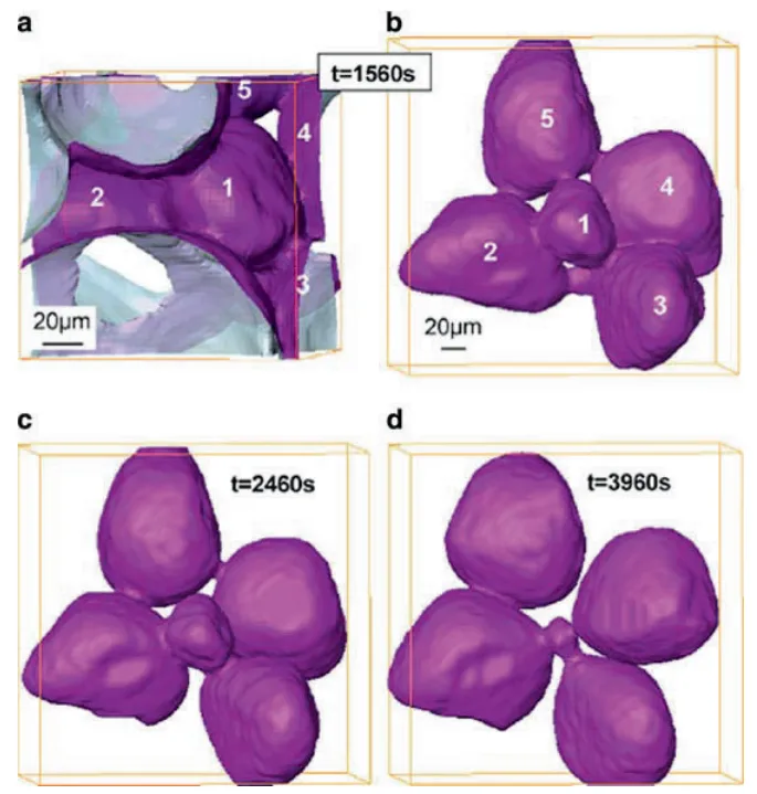
- Fig. 3.6 Variation of the average solid particle volume and equivalent radius with isothermal holding time
- Fig. 4.1 Schematic of the SSR process
- Fig. 4.2 Schematic of dendrite multiplication
- Fig. 4.3 Micrograph of Al–Cu alloy rheocast with SSR and then immediately quenched. Spheroidal primary grains are evident that formed during the initial period of solidification with subsequent dendritic microstructure that formed during the quench
- Fig. 4.4 Microstructures of reheated and quenched Al–Si alloy produced by (a) SSR and (b) electromagnetically stirred MHD continuous cast billet [35]
- Fig. 6.1 Devices used to measure the fluidity. (a) spiral; (b) vacuum suction
- Fig. 6.2 Apparent viscosity as a function of the solid fraction for an A356 alloy sheared at (filled square) 27 s1, (open square) 54 s1, (filled circle) 108 s1, and (open circle) 216 s1 during continuous cooling in the solidification interval at 1:2ıC min1 (from [11])
- Fig. 6.3 Apparent viscosity as a function of shearing time at 590ıC of a A356 alloy .fs D 0:35/ partially solidified with a shear rate of (filled square) 27 s1, (open square) 54 s1, (filled circle) 108 s1, and (open circle) 216 s1 (from [11])
- Fig. 6.4 Apparent viscosity as a function of shearing time at a shear rate of 200 s1 and at various temperatures corresponding to solid fraction fs D 0:3 (open square), 0.4 (filled circle), and 0.5 (filled square). Al-4.5%Cu-1.5%Mg (from [12])
- Fig. 6.5 Apparent viscosity of an A356 alloy as a function of the shear rate for various solid fractions (from [3])
- Fig. 6.6 Variation of the apparent viscosity at steady state as a function of the volume fraction of solid increased by the liquid volume fraction entrapped in the agglomerates for various shear rates (from [15])
- Fig. 6.7 Effect of the resting time tr on the hysteresis loops of a Sn-15%Pb alloy; tu is the time required to increase the shear rate up to its maximum value (from [2])
- Fig. 6.8 Shear rate jumps from 0 to 100 s1 after different rest times for Sn-15%Pb alloy at fraction solid 0.36 [23]
- Fig. 6.9 Apparent viscosity as a function of the isothermal shearing time of an A356 alloy partially solidified .fs D 0:35/, (open circle) without and (filled circle) with 15% SiC particles added at time t D 0. The shear rate is 108 s1 (from [11])
- Fig. 6.10 Fluidity Y of an Al-10%Cu alloy in the semisolid state characterized by a solid fraction gs. YL represents the fluidity of the liquid. The various curves are concerned with various stirring rates in revolutions/min. open circle: 340; open square: 482; open triangle: 695; star sqaure: 992 (from [25])
- Fig. 6.11 Schematic drawing of the vane viscometer; (a) complete viscometer; (b) crucible with thermocouple and vane; (c) four bladed vane
- Fig. 6.12 Schematic drawing of the drained oedometric compression apparatus used for Al alloys. From [37]. 1: I.R. lamp furnace; 2: piston; 3: filter support; 4: container; 5: specimen; 6: fabric of SiC Nicalon fibers; 7, 8: thermocouples
- Fig. 6.13 Schematic drawing of the drained triaxial compression apparatus. From [37]
- Fig. 6.14 Variation of the shear stress deduced from a compression test as a function of the isothermal holding time in the semisolid state before compression at 580ıC of an A357 alloy partially remelted .fs D 0:45/. The compression rate is 0:01 s1. From [11]
- Fig. 6.15 Variation of the shape factor of the globule as a function of the isothermal holding time in the semisolid state at 580ıC .fs D 0:45/ of an A357 alloy continuously cast (open circle) without and (filled circle) with electromagnetic stirring. The dashed line corresponds to perfect spheres. From [11]
- Fig. 6.16 Viscosity as a function of the shear rate for two aluminum alloys (A356, A357) and a magnesium alloy (AZ91) showing the shear thinning behavior of the alloys at solid fractions fs close to 0.50. From [39]
- Fig. 6.17 Step changes of strain rate with increasing values (left) and decreasing values (right) for a Al-6%Si-0.6%Mg alloy deformed in compression at 580ıC leading to a solid fraction of 0.55. From [11]
- Fig. 6.18 Micrograph of a A356 C 20%SiC composite after partial remelting and quenching showing the position of the SiC particles in the eutectic mixture (liquid in the semisolid state). From [41]
- Fig. 6.19 Effect of a step change of strain rate in the case of a A356 C 20% SiC composite deformed in compression in the semisolid state. From [42]
- Fig. 6.20 Variation of the filtration pressure as a function of the liquid fraction remaining in the specimen during drained compression at various strain rates (from [46])
- Fig. 6.21 Microstructures of an Al-15.8%Cu alloy after solidification (left) and after partial remelting at 555ıC and holding for 80 min (right). These micrographs were obtained from in-situ tomography experiments carried out at ESRF Grenoble (from [50])
- Fig. 7.1 Aluminum alloy 7075 is being forced vertically upwards into a die (see inset). The material has to flow around a corner and liquid segregation is occurring at that corner [53], partly because the temperature conditions are inappropriate. The rectangular outlined portion is the area shown in the micrograph
- Fig. 7.2 Load versus displacement for the rapid compression of a billet of A357 aluminum alloy in a thixoformer [56], illustrating that at relatively high fraction solid .572ıC/, the spheroids in the microstructure are deformed. At relatively low fraction solid .576ıC/, the spheroids are undeformed and the resistance to deformation is low. The closeness of these temperatures shows how sensitive the process is to temperature. The microstructures are taken from the edge of the billet after compression has been completed
- Fig. 7.3 Numerical simulation of die filling [61]. (a) Partial filling of die. (b) Modeling simulation of (a) where white corresponds to dark on (a). (c) Modeling simulation with improved die design showing smoother filling
- Fig. 7.4 Comparison of the effect of thixotropic relaxation time when a droplet of Sn15wt%Pb is allowed to fall from rest onto a plate located 6 cm below [72]. The droplet is assumed to be at 197ıC with approximately 47% solid fraction. Heat transfer to the plate is taken into account. Relaxation times (in ms) from top to bottom are 1, 2, 5, 10, and 50. The first column on the left has a zero rate, i.e., constant viscosity. The second has thinning and thickening rates of 1;000 s1. The third column has a 1;000 s1 thinning rate and a 0.0001 thickening rate. The last column has infinitely fast rates
- Fig. 7.5 Impact of a viscous drop with the same material as for Fig. 6.5 [72]. Times in ms from top to bottom are 0, 1, 5, 50, 100. Surface tension is dominating the flow in the 5–50 ms period; gravity is dominant by 100 ms
- Fig. 7.6 Comparison between simulation of flow into a cavity with a round obstacle assuming Newtonian behavior and assuming thixotropic behavior [73]. The direction of flow is upwards
- Fig. 7.7 Models of shear rate jump from 50 to 70 s1 in a 1 Pa.s Newtonian fluid in a rotational viscometer [75]. The implicit solver overestimates the width of the momentum diffusion peak
- Fig. 7.8 Shear rate jump from 1 to 100 s1 in SnPb alloy .fs D 0:36/ showing repeats of the same experiment and modeled fits using a spreadsheet and FLOW-3D predictions with a new ADI solver, which was introduced to address the challenges posed by fluids where the viscosity and shear rate change by many orders of magnitude in short times and spaces [76]
- Fig. 7.9 Experimental and modeled results (with FLOW3D) for compression tests on A356 aluminum alloy at two different temperatures [52]. For the higher temperature .578ıC/, there is hardly any initial peak at the beginning of the curve
- Fig. 7.10 Die filling with semisolid Sn15%Pb (fs D 0:55) [69]. (a) Stepped die shape with the undeformed finite element mesh in place ready for deformation. (b) Part way through the deformation before die filling is completed showing the distribution of the structural parameter , with D 1 representing a structure, which is still fully agglomerated
- Fig. 7.11 The fluid front for die filling with different viscosity models [70]. (a) Newtonian showing break-up of the flow front, (b) shear-thinning viscosity with a smoother flow front profile, (c) internal variable viscosity again with a smoother profile but with some significant differences from (b)
- Fig. 7.12 Comparison between Newtonian (on the left) and Bingham (on the right) filling behavior for a three-dimensional cavity with a cylindrical obstacle [82]
- Fig. 7.13 Flow patterns found by modeling for a Bingham fluid in a two-dimensional cavity [84]
- Fig. 7.14 Map showing the flow patterns identified in Fig. 34, plotting Bingham number Bi versus Reynolds number Re [84]
- Fig. 7.15 Flow instability of the “toothpaste” type in semisolid processing. The metal is filling from the right to the left [88]
- Fig. 7.16 Comparison between experimental and simulated filling of a cavity (initial ram velocity 0:8 ms1, diameter of tube 25 mm) [93]. (a) Fraction solid 0.52. (b) Fraction solid 0.58. (c) Fraction solid 0.73. In each figure, the upper part is the simulation and the lower part the experimental result obtained with interrupted filling. The material is flowing into the cavity from the left
- Fig. 7.17 (a) Cross-section through the semisolid material solidified in a tube in a Poiseuille-type experiment. The eutectic-rich concentric rings are due to veins of liquid formed in the shot sleeve. (b) shows such a vein formed at the limit of the dead zone in the shot sleeve (see inset). [93]
- Fig. 7.18 Isopotential curves used in the work by Zavaliangos [100] and compared with that in Martin, Favier and Suery [38]. (a) Constant liquid fraction fL and different levels of cohesion c (c is analogous to the structural variable ), (b) constant cohesion and different fL, and (c) different fractions of liquid fL [38]. c is the compressive stress and h the hydrostatic pressure in the solid phase
- Fig. 7.19 Comparison between the simulated and the observed contours of the flow front for different filling velocities. The simulations have been carried out using one set of model parameters [101]
- Fig. 7.20 Solid fraction field in the component, based on chemical analysis of the amount of lead (left) vs. simulated solid fraction field. Experimental and numerical results for a piston velocity of 50 mm s1 and an initial solid fraction of 62% with Sn15%Pb alloy [101]
- Fig. 7.21 Map of types of flow [107]. (a) Laminar, (b) Transient, (c) Turbulent. Bi is the Bingham number, Kc a rheological number, C1, C2 geometric constant and Re the Reynolds number. Kc, C1 and C2 are not specified in the paper
- Fig. 7.22 Three-dimensional process window for aluminum alloy A356 [107]. Mechanical properties are given in the two top boxes. The smaller boxes summarize the process parameter windows to obtain those mechanical properties (T is the temperature window, fs the solid fraction window, l the wall thickness and vm/. The higher the required mechanical properties, the smaller the three-dimensional process window (compare the right hand diagram with the left)
- Fig. 7.23 Finite element simulation with FORGE 3 of steel in the semisolid state. The colors represent the extent of deformation with red high and blue low. (Courtesy A. Rassili and coworkers [110])
- Fig. 7.24 (a) shows a schematic representation of the semisolid microstructure showing the presence of one inclusion of solid and entrapped liquid surrounded by a coating of liquid and solid bonds. In (b), a coated inclusion is embedded into a a matrix having the effective properties of the heterogeneous semisolid material. This is called the “homogeneous equivalent medium” (HEM). [113]
- Fig. 7.25 Comparison of “micro–macro” modeling with experimental results for “low” shear rates with Sn15%Pb alloy compressed between parallel plates [45, 113]
- Fig. 7.26 Comparison between “micro–macro” modeling and experimental results for “high” shear rates for Sn15%Pb alloy in concentric cylinder viscometer tests [2, 113]
- Fig. 9.1 Example of a modern 400 ton horizontal semisolid metal casting machine, and carousel induction heater
- Fig. 10.1 Mini horizontal continuous caster equipped with electromagnetic stirrer shown casting 75 mm SSM diameter billet, courtesy Hertwich GmbH
- Fig. 10.2 Typical carousel induction heater with solenoid coils connected in series to one power supply, courtesy IHS-Inductoheat
- Fig. 10.3 Horizontal induction slug heater with individual solenoid coils and lateral slug/boat transport system.
- Fig. 10.4 Semi-liquid convection slug heating system and cell for fuel rail production
- Fig. 10.5 Automotive fuel rails produced using horizontal convective heating and three phase injection die casting machines, courtesy Magnetti- Marelli S.p.A
- Fig. 10.6 Horizontal inductively heated slug, alloy 357
- Fig. 10.7 Illustration of the “elephant foot” effect after the first two-stage heating test (switching time at 140 s) (left) and of the semisolid billet keeping its initial shape after the second two-stage heating test (switching time at 205 s) [9]
- Fig. 10.8 The power input profile for a two-stage heating cycle and the temperature variation on the centre (large broken lines) and the edge (small broken lines). The heating power was lowered 205 s after heating had started [9]
- Fig. 10.9 Schematic of the new rheo-casting process (NRC) NRC: pouring – controlled cooling – sleeve filling – forming [3]
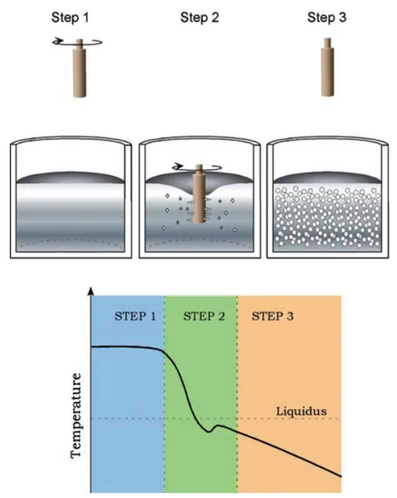
- Fig. 10.10 Schematic of the SSR process. Molten alloy is held above the liquidus (Step 1), then rapidly cooled and agitated for a controlled duration to a temperature below the liquidus (Step 2) before agitation and cooling ceases (Step 3).
- Fig. 10.11 SSR cell and graphite stirring rod in melt
- Fig. 10.12 Depicts the furnace and mixing configuration of DSF process with an anchor-shaped rotor with vertical shearing rods located close to the furnace walls for the scraping of solidifying material and vacuum drawing liquid aluminium through a tube into the shot sleeve of a cold chamber die casting press and photo insert the consistency of the slurry Reprinted with permission of ASM International(r). All rights reserved. www.asminternational.org
- Fig. 10.13 Schematic of a magnesium thixomoulding machine [7]
- Fig. 10.14 Schematic of Rheo-die casting process (RDC) [8]
- Fig. 11.1 Representative diaphragm style to minimise slug surface oxide entering the die cavity [10]
- Fig. 11.2 (a) Motorcycle swing arm mount, alloy 357, welded to 6,061 extrusions and heat treated by the customer, one-cavity die, (b) extrusion connector ATV frame, alloy 357, welded to 6,061 extrusions and heat treated by the customer and (c) flange for demolition hammer, alloy 319-T6 heat treated, two-cavity dies
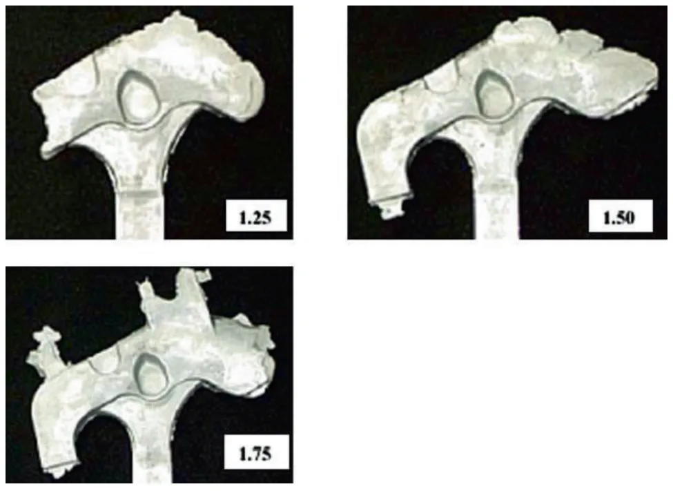
- Fig. 11.3 Fill test of the motorcycle swing arm mount showing 1.25%, 1.50% and 1.75% filling of the die cavity
- Fig. 11.4 (a) Die vacuum system with 7.5 HP pump and113.55L tank and (b) Vacuum runner for the part shown in Figure 11.5
- Fig. 11.5 Extrusion connectors produced without vacuum assist. Note non-fill areas (a) and Extrusion connectors produced with vacuum assist. Note all areas are now well filled
- Fig. 11.6 (a) Polished swing arm mount from Figure 4.21 (a), and (b) Chromium plated SSM cast part.
- Fig. 13.1 Parts produced by Stampal S.p.A for various automotive manufacturers using the MHD feedstock route
- Fig. 13.2 220t ThixomouldingR -machine from Japan Steel Works at Neue Materialien F¨urth GmbH (NMF)
- Fig. 13.3 Examples of magnesium thixomoulded parts from JSW Inc
- Fig. 13.4 Off-road motorcycle head-tube, alloy 357-T6 welded to a 6061 extrusion to make the complete frame (Vforge)
- Fig. 13.5 Small gasoline engine cartridge plate formed from alloy 357-T5, which replaced a machined alloy 6061-T6 piece (Vforge)
- Fig. 13.6 Small gasoline engine containing a number of SSM aluminium alloy parts including the entire crankcase, which is formed from alloy 357-T5 using a 2,500 ton machine and 5 in. diameter billet material. The cartridge plate in the previous figure and a companion SSM formed plate can be seen installed within the mechanism (Vforge)
- Fig. 13.7 Rheocast high strength safety parts: engine bracket (left) and Lagerbock (right) both using A 357 alloys (courtesy of Stampal S.p.A)
- Fig. 13.8 Air tank side parts for extruded tank profile; operating pressure 16 bar, very thin walls, 240 g each part using the MHD route. Material: New alloy, high YS (290 MPa) and E 12 (%) no H.T, low porosity, weldable, Audi. (Courtesy of SAG GmbH)
- Fig. 13.9 Left: Air manifold harness weldable on hydroformed part, thin wall, high ductility (VW and Audi) 130 g, replaces two parts previously produced by stamping. Front part of engine, vibration issues (fatigue); Centre: Antenna housing for tower mounted amplifier (TMA). Corrosion resistant, precision near net-shape, good surface quality, easy to coat (3–5 m silver), with good electrical and inter-modulation properties; Right: Flange energy crash absorber; near net-shape component for AUDI A6 V8 energy management system for bumpers (Courtesy of SAG GmbH)
- Fig. 13.10 Decorative pen and cover SSM formed from aluminium alloy 6061 in order to achieve a very high lustre polish. Aluminium alloy 357 polished to a low lustre finish because of the silicon content, and so this was one of the very first wrought aluminium alloy production applications (courtesy Vforge)
- Fig. 13.11 Golf putter formed from alloy 357-T5 over a brass rod acting as a weight (Vforge)
- Fig. 13.12 One of the very first SSM copper alloy production parts. A golf driver sole plate formed from aluminium bronze alloy replacing a stamped and machined alloy 377 piece. This application offered improved wear resistance from the superior alloy as well as a near net-shape without machining requirements (Vforge)
- Fig. 13.13 Section views of the oil pump filter housing produced by SSR (Courtesy Idra Prince)
- Fig. 13.14 Orthopedic knee joint piece replaced an investment cast steel piece saving 0.25 lb weight per knee! Alloy 357-T5 (Vforge)
- Fig. 13.15 Some die cast dies can be converted to SSM forming provided the gating is acceptable for SSM die design as discussed above. This centre-gated die was converted relatively easily and runner volume saved by moving the shot position to dead centre (Vforge)
![Fig. 7.8 Shear rate jump from 1 to 100 s1 in SnPb alloy .fs D 0:36/ showing repeats of the same experiment and modeled fits using a spreadsheet and FLOW-3D predictions with a new ADI solver, which was introduced to address the challenges posed by fluids where the viscosity and shear rate change by many orders of magnitude in short times and spaces [76]](https://castman.co.kr/wp-content/uploads/image-3601.webp)
7. 결론:
반고체 성형(SSM)은 고품질의 니어넷셰이프(near-net-shape) 부품을 생산하는 데 검증된 이점을 가진 성숙한 기술이다. 이 기술의 확산을 가로막는 주된 역사적 장벽은 틱소포밍 공정과 관련된 높은 원재료 비용이었다. 최근 현장에서 직접 슬러리를 생성하는 레오캐스팅 공정의 개발 및 산업화는 이러한 경제적 장벽을 극복하는 중요한 진전을 나타낸다. 이 새로운 접근법은 특수 빌렛의 필요성을 없애고 현장 스크랩 재활용을 가능하게 함으로써, SSM 기술이 고압 다이캐스팅 및 단조와 같은 기존 제조 공정과 비용 경쟁력을 갖추게 할 것으로 기대된다. 향후 기술 발전은 경량 합금에서의 광범위한 채택과 강철과 같은 고융점 합금으로의 기술 확장에 달려 있다.
8. References:
- M.C. Flemings, Metall. Trans. A 22A, 957 (1991)
- M.C. Flemings, Solidification Processing (McGraw-Hill Book, New York, NY, 1974)
- W. Kurz, D.J. Fisher, Fundamentals of Solidification, 3rd edn. (Trans Tech, Switzerland, 1989)
- J.H. Holloman, D. Turnbull, Prog. Met. Phys. 4, 333 (1953)
- A.L. Greer, Philos. Trans. R. Soc. Lond. A 361, 479 (2003)
- I. Maxwell, A. Hellawell, Acta. Metall. 23, 229 (1975)
- D.B. Spencer, R. Mehrabian, M.C. Flemings, Metall. Trans. 3, 1925 (1972)
- P.A. Joly, R. Mehrabian, J. Mater. Sci. 11, 1393 (1976)
- C.J. Quaak, Ph.D. thesis, TU Delft, 1996
- S.A. Metz, M.C. Flemings, Trans. Am. Foundrymen’s Soc: 77, 329 (1969)
- S.A. Metz, M.C. Flemings, Trans. Am. Foundrymen’s Soc. 77, 453 (1969)
- D.P. Spencer, R. Mehrabian, M.C. Flemings, Metall. Trans. 3, 1925 (1972)
- K.P. Young, C. Rice, in Viscous, Semi-Solid Forging of Aluminum Reduces Costs and Boosts Alloy Flexibility, Aluminum USA, Navy Pier, Chicago, USA, 2003
- H. Kaufmann, H. Wabusseg, P.J. Uggowitzer, in Metallurgical and Processing Aspects of the NRC Semi-Solid Casting Technology, Aluminum, 76. Jg., 2000
- J.A. Yurko, R.A. Martinez, M.C. Flemings, in SSR: the Spheroidal Growth Route to Semi-Solid Forming, Proceedings of the 8th International Conference on Semi-Solid Processing of Alloys and Composites, Limassol, Cyprus, 2004
전문가 Q&A: 가장 궁금한 질문에 대한 답변
Q1: 레오캐스팅과 틱소포밍의 가장 큰 차이점은 무엇인가요?
A1: 가장 큰 차이점은 출발 물질입니다. 틱소포밍은 특수 제작된 고체 빌렛을 재가열하여 반고체 상태로 만들지만, 레오캐스팅은 액체 용탕을 냉각 및 교반하여 현장에서 직접 반고체 슬러리를 만듭니다. 이 차이로 인해 레오캐스팅은 고가의 특수 빌렛이 필요 없어 원가 경쟁력이 높고 스크랩 재활용이 용이합니다.
Q2: 레오캐스팅이 최초의 아이디어였다면 왜 오랫동안 틱소포밍이 시장을 주도했나요?
A2: 초기 레오캐스팅 기술은 대량 생산 환경에서 슬러리의 품질을 일관성 있게 유지하기 어려웠고, 장비가 복잡했습니다. 반면, 틱소포밍은 품질이 보증된 빌렛을 사용하므로 공정 관리가 상대적으로 용이하여 먼저 상업화에 성공했습니다. 하지만 최근 SSR과 같은 혁신적인 레오캐스팅 기술이 등장하면서 이러한 단점들이 극복되고 있습니다.
Q3: SSR과 같은 새로운 레오캐스팅 공정에서 가장 중요한 제어 변수는 무엇인가요?
A3: 서적의 4장과 10.6.2장에 따르면, 가장 중요한 변수는 냉각 속도와 교반 강도(전단 속도)입니다. 용탕을 과냉각 상태로 빠르게 냉각시켜 미세한 핵을 다량으로 생성하고, 동시에 강한 전단력으로 수지상 성장을 억제하며 구상화를 촉진해야 합니다. 이 두 변수의 정밀한 제어가 최종 슬러리의 미세구조와 품질을 결정합니다.
Q4: 반고체 성형 부품의 기계적 특성은 기존 고압 다이캐스팅(HPDC)과 어떻게 다른가요?
A4: 반고체 성형 부품은 기공과 같은 내부 결함이 현저히 적기 때문에 HPDC 부품과 달리 T6와 같은 완전한 열처리가 가능합니다. 부록의 기계적 특성 데이터(Table 1)에서 볼 수 있듯이, A357-T6 합금의 경우 항복 강도 290 MPa, 인장 강도 340 MPa 수준의 우수한 기계적 특성을 보입니다. 이는 일반 HPDC 부품으로는 도달하기 어려운 수준으로, 부품의 강도, 연성, 피로 수명을 크게 향상시킵니다.
Q5: 새로운 레오캐스팅 기술이 널리 채택되기 위해 해결해야 할 과제는 무엇인가요?
A5: 서적의 14장에서 언급하듯이, 가장 큰 과제는 초기 설비 투자 비용과 운영 비용 대비 실현되는 이익(생산성 향상, 품질 개선)의 균형을 맞추는 것입니다. 또한, 현장에서 용탕을 직접 다루기 때문에 산화물 관리와 같은 전통적인 주조 공정의 문제들을 다시 해결해야 합니다. 기술의 장점을 입증하고 경제성을 확보하여 자동차 산업과 같은 대량 생산 시장에 본격적으로 진입하는 것이 중요합니다.
결론: 더 높은 품질과 생산성을 향한 길
본 연구는 반고체 성형 기술이 기존 주조 공정의 한계를 극복할 수 있는 강력한 대안임을 명확히 제시합니다. 특히, 고비용 구조로 인해 시장 확대에 어려움을 겪었던 틱소포밍의 단점을 극복한 새로운 레오캐스팅 기술의 등장은 산업계에 중요한 시사점을 던져줍니다. 원가 절감, 품질 향상, 설계 자유도 확대라는 세 마리 토끼를 동시에 잡을 수 있는 이 기술은 고성능, 고신뢰성이 요구되는 미래 부품 시장의 핵심 기술이 될 잠재력을 가지고 있습니다.
CASTMAN은 최신 산업 연구 결과를 고객의 생산 현장에 적용하여 최고의 생산성과 품질을 달성할 수 있도록 돕는 데 전념하고 있습니다. 본 보고서에서 논의된 기술적 과제와 가능성이 귀사의 운영 목표와 일치한다면, 지금 바로 CASTMAN의 엔지니어링 팀에 문의하여 이러한 원칙을 귀사의 부품에 어떻게 적용할 수 있는지 논의해 보십시오.
저작권 정보
이 콘텐츠는 David H. Kirkwood 외 저자의 논문 "Semi-solid Processing of Alloys"를 기반으로 한 요약 및 분석 자료입니다.
출처: https://doi.org/10.1007/978-3-642-00706-4
본 자료는 정보 제공 목적으로만 사용될 수 있으며, 무단 상업적 사용을 금지합니다. Copyright © 2025 CASTMAN. All rights reserved.