본 기술 요약은 Randeep Singh이 RMIT 대학에서 발표한 "2상 및 단상 루프 냉각 시스템을 사용한 고성능 데스크톱 및 노트북 마이크로프로세서의 열 제어(Thermal Control of High-Powered Desktop and Laptop Microprocessors Using Two-Phase and Single-Phase Loop Cooling Systems)" (2006년 3월) 논문을 기반으로 합니다. 이 자료는 HPDC 전문가들을 위해 캐스트맨(CASTMAN)의 전문가들이 Gemini, ChatGPT, Grok과 같은 LLM AI의 도움을 받아 분석하고 요약했습니다.
키워드
- 주요 키워드: 2상 루프 냉각 시스템
- 보조 키워드: 소형 루프 히트 파이프(mLHP), 마이크로프로세서 열 제어, 단상 액체 냉각, 마이크로채널 히트 싱크, 소결 다공성 히트 싱크, 모세관 펌프 루프(CPL), 고열유속 냉각
핵심 요약
- 해결 과제: 데스크톱(80-130W) 및 노트북(25-50W) 마이크로프로세서의 전력 밀도가 급격히 증가하면서 히트 파이프 및 증기 챔버와 같은 기존 냉각 기술이 한계에 도달했습니다. 미래의 전자 시스템에는 더욱 발전된 열 관리 솔루션이 필요합니다.
- 연구 방법: 본 연구는 수동형 2상 열전달(소형 루프 히트 파이프, mLHP)과 능동형 단상 액체 냉각(마이크로채널 및 소결 다공성 히트 싱크 사용)을 기반으로 한 다양한 열 설계를 개발하고 그 특성을 분석했습니다.
- 핵심 성과: 2상 냉각 장치는 노트북과 같은 소형 기기에서 발생하는 높은 열유속(최대 70W/cm²)에 대해 매우 신뢰성 높은 수동형 솔루션임이 입증되었습니다. 고성능 데스크톱의 극한 열유속(최대 400W/cm²)에는 능동형 단상 액체 냉각 시스템이 더 효과적이지만 구조적으로 복잡합니다.
- 결론: 수동형 2상 냉각과 능동형 단상 냉각 중 어느 하나가 절대적으로 우월한 것은 아니며, 특정 응용 분야의 열유속, 공간 제약, 신뢰성 요구사항에 따라 최적의 솔루션이 달라집니다.
해결 과제: 본 연구가 HPDC 전문가에게 중요한 이유
전자기기의 처리 능력이 기하급수적으로 증가함에 따라 발생하는 폐열 또한 급증하고 있습니다. 현재 데스크톱 및 서버의 CPU는 80~130W, 노트북은 25~50W의 열을 방출하며 이 수치는 계속해서 증가하고 있습니다. 이러한 열 문제는 칩셋 자체의 면적이 줄어들면서 더욱 심각해지며, 70W/cm²를 초과하는 극한의 열유속을 발생시킵니다.
엔지니어와 설계자에게 칩 표면 온도를 100°C 미만으로 유지하는 것은 신뢰성을 위한 타협할 수 없는 필수 요건입니다. 표준 히트 파이프와 증기 챔버를 포함한 기존의 냉각 방식은 이러한 고성능 시스템의 미래 열 수요를 충족시키지 못할 것으로 예상됩니다. 이로 인해 소형 전자기기에 통합할 수 있는 혁신적이고 신뢰성 높은 고성능 열 제어 기술에 대한 필요성이 절실해졌습니다. 본 연구는 차세대 수동형 및 능동형 루프 냉각 시스템을 탐구함으로써 바로 이 문제를 해결하고자 합니다.
접근 방식: 연구 방법론 분석
이 시급한 열 문제를 해결하기 위해, 연구진은 두 가지 뚜렷한 원리에 기반한 여러 첨단 냉각 프로토타입을 개발하고 그 특성을 분석했습니다.
- 2상 냉각 시스템 (수동형): 본 연구는 수동적으로 작동하는 소형 루프 히트 파이프(mLHP)의 프로토타입을 개발하고 테스트하는 데 중점을 두었습니다. 이 장치는 별도의 펌프 없이 윅 구조의 모세관 힘을 이용하여 작동 유체를 순환시키고, 증발-응축 사이클을 통해 열을 전달합니다. 프로토타입에는 평판 디스크형 증발기와 혁신적인 박형 직사각형 증발기를 갖춘 mLHP가 포함되었습니다.
- 단상 액체 냉각 시스템 (능동형): 더 높고 집중된 열유속을 처리하기 위해 연구에서는 능동형 액체 냉각을 탐구했습니다. 여기에는 마이크로채널 및 소결 다공성 매체와 같은 혁신적인 미세 구조를 가진 히트 싱크 개발이 포함되었습니다. 이 시스템은 펌프를 사용하여 액체 냉각수를 능동적으로 순환시켜 훨씬 더 높은 열 제거 용량을 제공할 잠재력을 가집니다.
이러한 개별 시스템을 구축, 테스트 및 비교함으로써, 본 연구는 다양한 고밀도 마이크로프로세서 응용 분야에 대한 각 시스템의 성능, 능력 및 적합성에 대한 포괄적인 분석을 제공합니다.
핵심 성과: 주요 연구 결과 및 데이터
이 광범위한 조사를 통해 차세대 냉각 기술의 성능과 적용에 대한 중요한 통찰력을 얻었습니다.
- 성과 1: 2상 mLHP는 소형, 고열유속 응용 분야에서 탁월한 성능을 보였습니다. 개발된 평판 디스크형 증발기를 갖춘 소형 루프 히트 파이프(mLHP)는 최대 70W/cm²의 높은 열유속을 제거하고 150mm 이상 열을 전달할 수 있어 노트북 마이크로프로세서를 위한 매우 신뢰성 높고 다목적 솔루션임이 입증되었습니다.
- 성과 2: 단상 시스템은 극한의 열유속을 효과적으로 해결합니다. 극심한 전력 밀도를 가진 데스크톱 및 서버 응용 분야에서는 단상 액체 냉각 시스템이 우수한 성능을 보였습니다. 미세 구조(마이크로채널 또는 소결 다공성 매체 등)를 가진 히트 싱크는 최대 400W/cm²의 집중된 열유속을 처리할 수 있는 것으로 나타났습니다.
- 성과 3: 명확한 성능 상충 관계(Trade-Off)가 존재합니다. 비교 연구(9장)를 통해 2상 수동형 시스템은 낮거나 중간 수준의 높은 열유속에 대해 매우 신뢰성 있고 효율적이라는 점이 명확해졌습니다. 그러나 극한의 열 부하에서는 성능이 저하되며, 이때는 복잡하고 펌프가 필요한 단상 능동형 시스템이 더 효과적입니다(그림 9.12 참조).
- 성과 4: 증발기 설계는 소형화에 매우 중요합니다. 본 연구는 보상 챔버를 측면으로 재배치하여 두께가 5mm에 불과한 평판 직사각형 증발기를 갖춘 mLHP를 성공적으로 개발했습니다. 이는 상당한 박형화를 달성했지만, 10mm 디스크형 설계에 비해 약간의 성능 저하가 발생했으며, 이는 소형화에서 중요한 설계 고려사항을 강조합니다(그림 6.13).
- 성과 5: 재료 호환성과 순도는 매우 중요합니다. 연구를 통해 비응축성 가스(NCG) 생성이 성능을 저하시키고 시동 시간을 증가시킬 수 있음을 확인했습니다. 적절한 세척 절차와 작동 유체의 탈기(degassing)는 장기적인 신뢰성 있는 작동을 보장하는 데 필수적입니다(그림 5.37, 그림 5.41).
HPDC 제품을 위한 실질적 시사점
본 논문은 전자제품 냉각에 초점을 맞추고 있지만, 첨단 열 관리 원칙은 보편적으로 적용될 수 있습니다. 다이캐스트 인클로저에 내장될 수 있는 고성능 부품을 다루는 엔지니어에게 이러한 연구 결과는 귀중한 통찰력을 제공합니다.
- 부품 및 시스템 설계자를 위해: 본 연구는 올바른 첨단 냉각 기술을 선택하기 위한 데이터 기반 프레임워크를 제공합니다. 9장의 비교 연구는 상당하지만 극한은 아닌 열 부하를 가진 고신뢰성 응용 분야(예: 노트북 또는 모바일 기기)에는 수동형 2상 mLHP가 탁월한 선택임을 명확히 보여줍니다. 최대 열 제거가 최우선인 시스템(예: 고성능 서버)에는 능동형 단상 액체 냉각이 더 우수합니다.
- 품질 및 신뢰성 엔지니어를 위해: 비응축성 가스(NCG) 생성에 대한 연구 결과(5.9장)는 밀봉된 열 관리 시스템에서 재료 호환성과 제조 청결도의 중요성을 강조합니다. 이 연구는 미량의 불순물조차도 시간이 지남에 따라 성능 저하를 유발할 수 있음을 보여주며, 이는 장기 수명 제품에 있어 매우 중요한 교훈을 제공합니다.
- R&D 및 혁신 팀을 위해: 5mm 두께의 평판 직사각형 증발기라는 새로운 설계(6장)는 강력한 열 솔루션을 소형화하는 실용적인 길을 제시합니다. 주요 구성 요소를 재배치하여 전체 두께를 줄이는 이 개념은 열 관리를 소형 제품 어셈블리에 직접 통합하는 데 있어 혁신적인 영감을 줄 수 있습니다.
논문 상세 정보
2상 및 단상 루프 냉각 시스템을 사용한 고성능 데스크톱 및 노트북 마이크로프로세서의 열 제어
1. 개요:
- 제목: Thermal Control of High-Powered Desktop and Laptop Microprocessors Using Two-Phase and Single-Phase Loop Cooling Systems
- 저자: Randeep Singh
- 발표 연도: 2006년 3월
- 발표 기관: RMIT University (철학박사 학위 논문)
- 키워드: 2상 냉각, 단상 냉각, 루프 히트 파이프, 마이크로채널 히트 싱크, 소결 다공성 히트 싱크, 열 제어, 마이크로프로세서
2. 초록:
고성능 소형 컴퓨터의 발전으로 마이크로프로세서의 전력 소모 요구사항이 상당히 증가했습니다. 현재 데스크톱 및 서버 컴퓨터의 CPU 발열량은 80~130W, 노트북은 25~50W에 달하며, 새로운 시스템에서는 데스크톱 200W, 노트북 70W 수준까지 도달했습니다. 동시에 칩셋의 발열 면적은 1~4cm²로 작아졌습니다. 이 문제는 제한된 공간과 칩 표면 온도를 100°C 미만으로 유지해야 하는 제약으로 인해 더욱 복잡해집니다. 히트 파이프나 증기 챔버 같은 기존 2상 기술 및 현재의 단상 냉각 시스템 설계로는 미래 컴퓨터 시스템의 열 요구사항을 충족시키기 어려울 것으로 예상됩니다. 이 문제를 해결하기 위해 2상 및 단상 열전달을 기반으로 한 다양한 열 설계를 개발하고 고밀도 마이크로프로세서의 열 제어를 위한 특성을 분석했습니다. 2상 기술 분야에서는 두께가 5mm 또는 10mm로 작으면서도 최대 70W/cm²의 열유속을 처리할 수 있는 모세관 구동 방식의 수동형 루프 히트 파이프 프로토타입 두 가지를 설계하고 테스트했습니다. 이 장치들은 노트북 마이크로프로세서의 열 요구사항에 매우 잘 대응했습니다. 단상 냉각 시스템의 열 특성은 최대 400W/cm²의 집중된 열유속을 처리할 수 있도록 향상되었습니다. 이는 마이크로채널이나 소결 미세 다공성 매체를 포함하는 혁신적인 미세 구조의 히트 싱크를 개발함으로써 가능해졌습니다. 본 연구의 결과, 2상 냉각 장치는 높은 열유속과 제한된 공간을 가진 노트북 마이크로프로세서 냉각에 매우 신뢰성 높은 열 솔루션을 제공한다고 결론 내릴 수 있습니다. 그러나 수동 장치의 열 성능은 매우 높은 열유속에서는 제한됩니다. 따라서 미래 고성능 전자 시스템의 효과적인 관리를 위해 냉각 기술을 더욱 탐구할 필요가 있습니다. 액체 냉각 시스템은 극도로 높은 열유속을 효과적으로 처리할 수 있지만, 펌프와 같은 능동 부품이 필요하고 전력을 소모하므로 구조적으로 복잡하고 신뢰성이 떨어질 수 있습니다.
3. 서론:
열 제어는 전자 장비의 기본적인 요구 사항입니다. 논문의 1장에서 자세히 설명된 바와 같이, 노트북과 데스크톱 모두에서 마이크로프로세서의 전력 소모 증가는 기존의 냉각 방식을 불충분하게 만들었습니다. 간단한 장치는 자연 대류에 의존하지만, 고성능 컴퓨터는 고급 열 솔루션을 필요로 합니다. 히트 파이프와 증기 챔버는 효과적이었지만, 미래의 전력 밀도는 더 성능이 뛰어난 시스템을 요구합니다. 이로 인해 본 연구에서는 차세대 컴퓨터의 열 요구를 해결하기 위해 혁신적인 2상 루프 히트 파이프와 미세 구조를 갖춘 향상된 단상 액체 냉각 시스템을 개발하게 되었습니다.
4. 연구 요약:
연구 주제 배경:
본 연구는 현대 컴퓨터의 핵심 과제인 열 관리를 다룹니다. 마이크로프로세서의 전력 밀도 증가와 크기 감소로 인해 기존의 공랭, 히트 파이프, 증기 챔버를 넘어서는 솔루션이 필요합니다.
이전 연구 현황:
이전 연구들은 주로 항공우주 분야에서 루프 히트 파이프(LHP)와 모세관 펌프 루프(CPL)를 견고한 2상 시스템으로, 고열유속 응용 분야에서 마이크로채널을 이용한 단상 액체 냉각을 확립했습니다. 그러나 상업용 전자제품을 위한 소형화되고 비용 효율적인 버전에 대한 연구, 특히 유사한 제약 조건 하에서의 성능 비교는 추가적인 조사가 필요했습니다.
연구 목적:
주요 목표는 노트북 및 데스크톱 마이크로프로세서의 높은 열유속을 관리하기 위해 2상 및 단상 냉각에 기반한 다양한 열 솔루션을 조사, 설계 및 개발하는 것이었습니다. 여기에는 노트북용 소형 LHP(mLHP) 프로토타입과 데스크톱용 미세 구조 히트 싱크 개발 및 성능 비교가 포함됩니다.
핵심 연구:
연구의 핵심은 두 가지 주요 냉각 시스템의 설계, 제작 및 실험적 테스트를 포함합니다.
- 두 가지 다른 평판 증발기 설계(10mm 디스크 및 5mm 직사각형)를 가진 2상 소형 루프 히트 파이프(mLHP).
- 마이크로채널 히트 싱크와 소결 다공성 히트 싱크를 사용한 단상 액체 냉각 시스템.
이후 단일 및 다중 열원에 대해 2상 히트 파이프 모듈과 단상 마이크로채널 시스템의 성능을 비교하는 연구가 수행되었습니다.
5. 연구 방법론
연구 설계:
본 연구는 일련의 실험적 조사로 설계되었습니다. 각 냉각 시스템(디스크 증발기 mLHP, 직사각형 증발기 mLHP, 마이크로채널 히트 싱크, 소결 다공성 히트 싱크)의 프로토타입을 설계하고 제작했습니다. 성능 예측을 위해 LHP에 대한 이론적 모델도 개발되었습니다.
데이터 수집 및 분석 방법:
각 프로토타입에 대한 실험 테스트 베드가 구축되었습니다. 데이터는 다양한 지점의 T-타입 열전대, 압력 변환기, 디지털 전력계를 사용하여 수집되었으며 열 부하를 제어하고 측정했습니다. 데이터 수집 시스템은 5-10초마다 온도를 기록했습니다. 열 성능은 증발기 온도, 열 저항(증발기, 전체), 열 부하 및 냉각수 유량의 함수로서의 열전달 계수와 같은 핵심 지표를 계산하여 분석되었습니다.
연구 주제 및 범위:
본 연구는 여러 핵심 주제를 다룹니다:
- 노트북 냉각용(최대 70W) 2상 mLHP의 설계 및 특성 분석.
- 데스크톱 냉각용(최대 200W, >400W/cm²) 단상 액체 냉각 시스템의 설계 및 특성 분석.
- mLHP의 시동 현상, 유체 재고량 효과, 기울기 효과 및 비응축성 가스(NCG) 생성 분석.
- 단일 및 다중 열원에 대한 2상 대 단상 냉각의 직접적인 성능 비교.
6. 주요 결과:
주요 결과:
- 소형 루프 히트 파이프(mLHP)는 노트북의 고열유속 칩셋(최대 70W/cm²)을 냉각하기 위한 효과적이고 신뢰성 있는 수동형 기술입니다.
- 미세 구조(마이크로채널, 소결 다공성 윅)를 이용한 액체 냉각은 고성능 데스크톱 시스템의 극한 열유속(최대 408W/cm²)에 대한 실행 가능한 접근 방식입니다.
- 2상 모세관 구동 시스템은 능동 부품(펌프)이 없어 더 신뢰성이 높지만, 단상 시스템은 초고열유속에 대해 더 나은 열 제어를 제공합니다.
- 보상 챔버 재배치와 같은 새로운 설계 개념을 통해 mLHP 증발기의 두께를 10mm에서 5mm로 축소하는 것이 가능합니다.
- mLHP의 작동 특성은 윅 특성(재료, 기공 크기, 다공성)과 유체 충전량에 크게 의존합니다. 이중 다공성 윅이 단일 다공성 윅보다 더 나은 성능을 보입니다.
- 열 저항과 압력 강하 측면에서 마이크로채널 히트 싱크의 열 성능이 소결 다공성 히트 싱크보다 우수한 것으로 나타났습니다.
그림 목록:
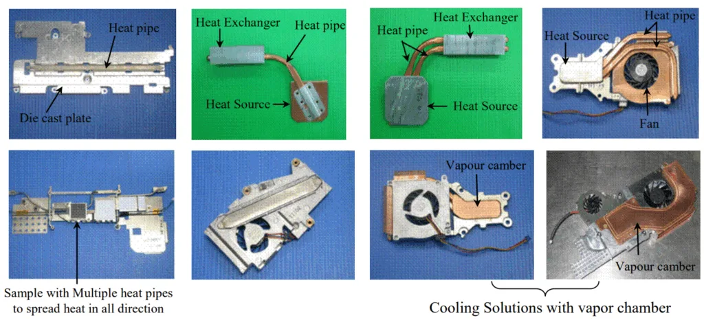
- Figure 1.1 Trends in Thermal Solutions for Laptop PCs
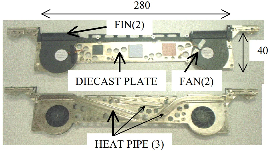
- Figure 1.2 Hybrid thermal control system for laptop microprocessors.
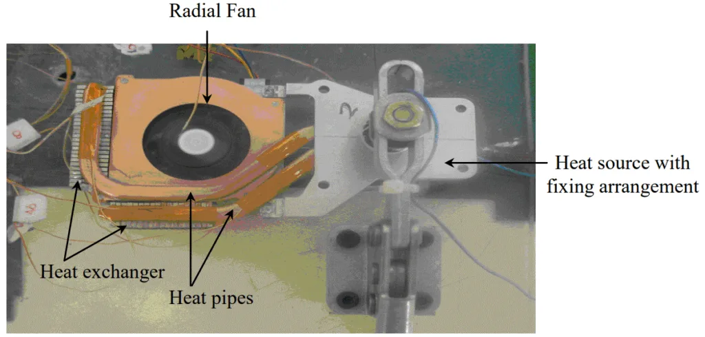
- Figure 1.3 Remote Heat Exchanger for cooling laptop microprocessors.
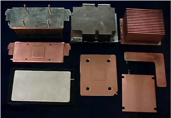
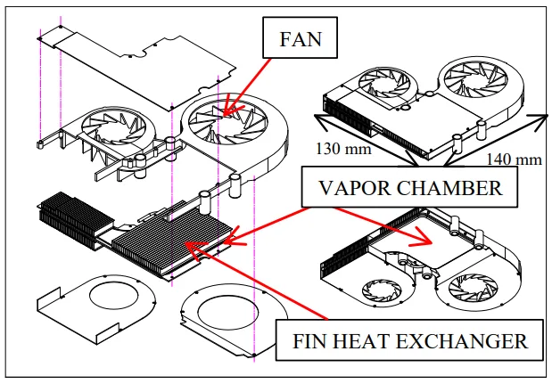
- Figure 1.4 Different designs of vapour chamber used for laptop cooling
- Figure 1.5 Thermal control system with vapour chamber for laptop cooling
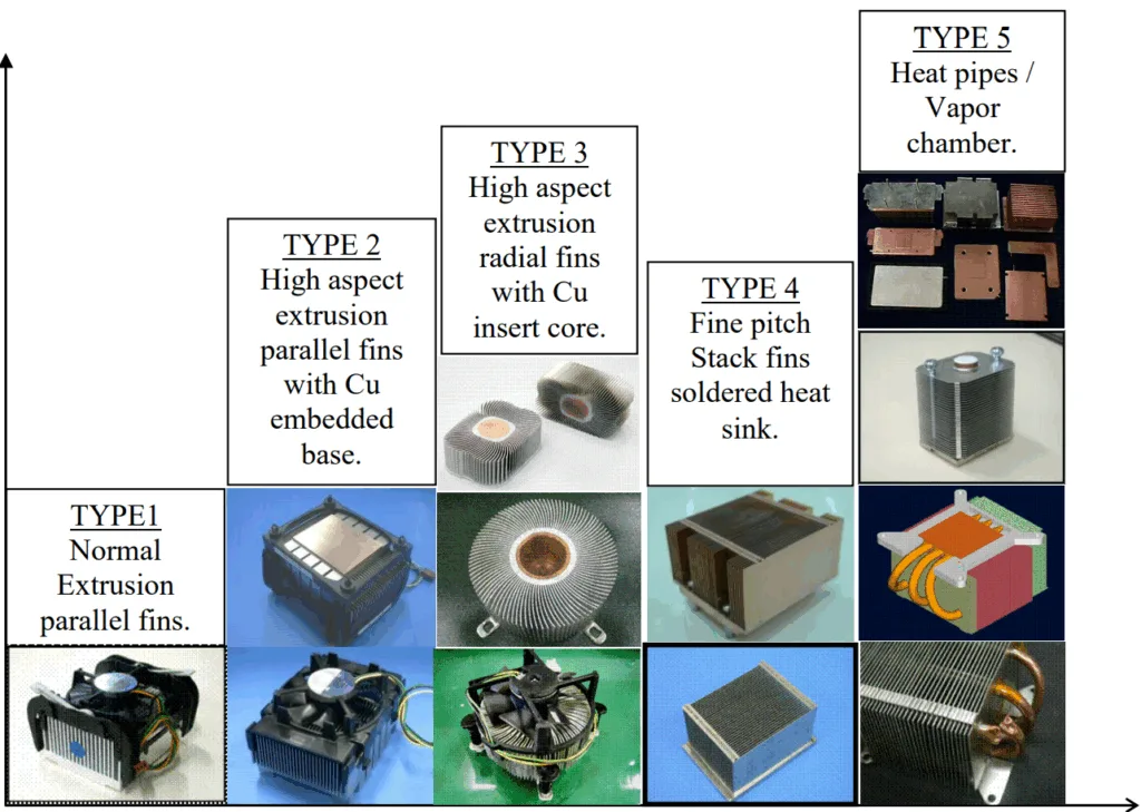
- Figure 1.6 Different Types of Thermal Solution for Desktop Computer Cooling
- Figure 1.7 Thermal Solution Trends
- Figure 2.1 Conventional Capillary Driven Heat Pipe
- Figure 2.2 Arterial Heat Pipes
- Figure 2.3 Separated lines heat pipe
- Figure 2.4 Loop Scheme
- Figure 2.5 Loop Heat Pipe (LHP)
- Figure 2.6 Capillary Pumped Loop (CPL)
- Figure 2.7 Schematic of Loop Heat Pipe
- Figure 2.8 Scheme of organisation of evaporation zone by the principle of an inverted meniscus
- Figure 2.9 Available cooling space inside the laptop computer
- Figure 2.10 Different variants of LHP condenser
- Figure 2.11 Schematic of a Microchannel Heat Sink
- Figure 2.12 Schematic of a Sintered Porous Heat Sink
- Figure 3.1 LHP schematic (Ref: Maydanik & Fershtater, 1997)
- Figure 3.2 P-T diagram of the LHP working cycle
- Figure 3.3 Schematic of the miniature LHP showing various control volumes for the energy balance
- Figure 3.4 Energy Balance inside Control Volume 1
- Figure 3.5 Energy Balance inside Control Volume 2
- Figure 3.6 Energy Balance inside Control Volume 3
- Figure 3.7 Schematics of the LHP condenser
- Figure 3.8 Thermal circuit diagram for the mLHP showing thermal resistances of different components
- Figure 4.1 Prototype of Miniature Loop Heat Pipe (mLHP) showing the different components
- Figure 4.2 Exploded view of the capillary evaporator showing the different parts
- Figure 4.3 mLHP Evaporator
- Figure 4.4 Details of Vapour removal channels
- Figure 4.5 Details of Fin-and-Tube Condenser
- Figure 4.6 Charging procedure for mLHP
- Figure 4.7 Schematic of the experimental prototype and test layout for the mLHP
- Figure 5.1 Start-up of the mLHP at 15W input power
- Figure 5.2 Heat load dependence of the evaporator surface temperature
- Figure 5.3 Heat transfer coefficient versus applied heat load
- Figure 5.4 Heat pipe thermal resistance versus applied heat load
- Figure 5.5 Total thermal resistance versus applied heat load
- Figure 5.6 Evaporator thermal resistance versus applied heat load
- Figure 5.7 Start-up failure due to leakage in external sealing
- Figure 5.8 Start-up failure due to internal leakage
- Figure 5.9 Start-up failure of the mLHP under 30% fluid charge
- Figure 5.10 Start-up failure of the mLHP under 40% fluid charge
- Figure 5.11 Start-up trend shown by the mLHP when the liquid-vapour interface is already present in the evaporator before heat load is applied
- Figure 5.12 Start-up trend shown by the mLHP when in the pre start state the vapour removal channels are completely flooded with liquid
- Figure 5.13 Start-up trend shown by the mLHP when in the pre start state insufficient fluid inventory is present in the compensation chamber
- Figure 5.14 Comparison of theoretically predicted and experimentally determined results for the mLHP design with sintered nickel capillary structure
- Figure 5.15 Comparison of predicted and experimental results for the mLHP design with sintered copper capillary structure
- Figure 5.16 Effect of the fluid charge on the evaporator wall temperature for the given range of applied heat loads
- Figure 5.17 Test setup to measure the thermal performance of the mLHP at different tilt angles
- Figure 5.18 Effect of the tilt angle on the thermal performance of the mLHP
- Figure 5.19 Change in the fluid distribution inside the compensation chamber with the increase in the tilt angle
- Figure 5.20 Start-up of the mLHP with uniform heating of the evaporator active face at input power of 20 W
- Figure 5.21 Start-up of the mLHP with non-uniformly heating of the evaporator active face at input power of 20 W
- Figure 5.22 Thermal performance (evaporator wall temperature versus applied heat load) of mLHP for uniform as well as non uniform heating modes
- Figure 5.23 Evaporator thermal resistance versus applied heat load for uniform and non uniform heating modes
- Figure 5.24 Heat pipe thermal resistance versus applied heat load for uniform and non-uniform heating modes
- Figure 5.25 Total thermal resistance versus applied heat load for uniform and non uniform heating modes
- Figure 5.26 Heat load dependence of the evaporator wall temperature with nickel and copper wicks
- Figure 5.27 Heat load dependence of the evaporator wall temperature for mLHP with nickel and copper wicks
- Figure 5.28 Evaporator thermal resistance versus applied heat load for mLHP with nickel and copper wicks
- Figure 5.29 Heat load dependence of the evaporator wall temperature for monoporous copper wicks with different physical properties
- Figure 5.30 Structure of biporous wick
- Figure 5.31 Combined Copper wick showing monoporous and biporous layers
- Figure 5.32 Heat load dependence of the evaporator wall temperature for mLHP with monoporous and combined wick
- Figure 5.33 Evaporator temperature trend with respect to the applied heat load for the number of trial runs made on the mLHP over a period of time
- Figure 5.34 Change in the absolute pressure inside the loop due to the generation of NCG over a period of time.
- Figure 5.35 Oxidation of the container and wick material due to the reaction and absorption of the NCG gas accumulated inside the compensation chamber
- Figure 5.36 Temperature profile on the surface of the compensation chamber taken with the help of five K-Type thermocouples
- Figure 5.37 Start-up trend shown by the mLHP with and without NCG
- Figure 5.38 Design arrangement for purging the NCG from the mLHP system
- Figure 5.39 Experimental Set-up for purging the NCG from the mLHP
- Figure 5.40 Operational Characteristics of the mLHP before and after purging procedure
- Figure 5.41 Operational Characteristics of the mLHP before and after degassing procedure
- Figure 6.1 Schematic of Flat Rectangular Evaporator mLHP showing the components
- Figure 6.2 Exploded view of the capillary evaporator showing the parts
- Figure 6.3 mLHP Evaporator
- Figure 6.4 Plan view of the evaporator body
- Figure 6.5 Details of vapour removal channels
- Figure 6.6 Details of Fin-and-Tube Condenser
- Figure 6.7 Experimental set up for testing the flat rectangular evaporator mLHP
- Figure 6.8 Start-up of rectangular evaporator mLHP at 20 W input power
- Figure 6.9 Heat load dependence of the rectangular evaporator mLHP evaporator temperature
- Figure 6.10 Evaporator thermal resistance versus applied heat load for the rectangular evaporator mLHP
- Figure 6.11 Total thermal resistance versus applied heat load for the rectangular evaporator mLHP
- Figure 6.12 Comparison of the heater interface temperature for the disk shaped evaporator mLHP and rectangular evaporator mLHP at the same range of input heat loads.
- Figure 6.13 Comparison of the evaporator temperature for the disk shaped evaporator mLHP and rectangular evaporator mLHP at the same range of input heat loads.
- Figure 6.14 Cross section of the disk shaped evaporator showing internal structures and directions of the liquid and heat flows relative to each other
- Figure 6.15 Cross section of the rectangular shaped evaporator showing internal structures and directions of the liquid and heat flows relative to each other
- Figure 6.16 Evaporator thermal resistance for the disk shaped evaporator mLHP and rectangular evaporator mLHP at the same range of input heat loads.
- Figure 6.17 Total thermal resistance for the mLHP with disk shaped evaporator and rectangular evaporator at the same range of input heat loads.
- Figure 7.1 Layout of the Microchannel heat sink assembly
- Figure 7.2 Schematic of the Microchannels
- Figure 7.3 Internal details and liquid flow path inside the microchannel heat sink
- Figure 7.4 Experimental Setup to test microchannel heat sink
- Figure 7.5 Cross sectional view of the microchannel heat sink and distributed finned heat exchanger showing the fluid flow pattern inside the cooling unit.
- Figure 7.6 Test bed for the Microchannel heat sink
- Figure 7.7 Experimental setup for open loop system
- Figure 7.8 Experimental setup for closed loop system
- Figure 7.9 Test facility for the heat sink showing the location of the thermocouples on the microchannel heat sink
- Figure 7.10 Test facility for the heat sink showing the location of the thermocouples on the Finned Heat Exchanger
- Figure 7.11 Heat load dependence of the Interface temperature of the microchannel heat sink with the 11mm x 13mm heat source
- Figure 7.12 Cold plate thermal resistance and total thermal resistance of the microchannel heat sink with respect to the applied heat load using 11mmx13mm heat source
- Figure 7.13 Heat load dependence of the Interface temperature of the microchannel heat sink with different heater sizes (7 x7 mm², 11 x13 mm²)
- Figure 7.14 Variation of the cold plate thermal resistance of the microchannel heat sink with the applied heat load with different heater sizes (7 x7 mm², 11 x13 mm²)
- Figure 7.15 Variation of the total thermal resistance of the microchannel heat sink with the applied heat load for different heater sizes (7 x7 mm², 11 x13 mm²)
- Figure 7.16 Heat load dependence of the interface temperature for the microchannel heat sink for different flow rates
- Figure 7.17 Cold plate thermal resistance of the microchannel heat sink with respect to the applied heat load for different flow rates
- Figure 7.18 Heat transfer coefficient of the microchannel heat sink with respect to the applied heat load for different flow rates
- Figure 7.19 Variation of the heat transfer coefficient with applied heat load: Comparison of the experimental and the predicted results by using different entry length conditions and flow regimes
- Figure 7.20 Variation of the Nusselt number with Reynolds number: Comparison of the experimental and the predicted results by using different entry length conditions and flow regimes
- Figure 8.1 Layout of Sintered Porous Heat Sink
- Figure 8.2 Internal structure of the Sintered Porous Heat Sink
- Figure 8.3 Picture of the cooling section showing the Porous Insert inside the machined rectangular channel
- Figure 8.4 Exploded View of the Sintered Porous Heat Sink
- Figure 8.5 Sample of the sintered porous material at different magnifications showing rounded irregular copper granular particles fused together as the result of the sintering process
- Figure 8.6 Cross Sectional view of the sintered porous heat sink showing the liquid flow pattern inside the cooling section
- Figure 8.7 Experimental Setup of the Sintered Porous Heat Sink
- Figure 8.8 Test Facility for the Sintered Porous Heat Sink showing the location of the thermocouple points
- Figure 8.9 Pressure drop versus flow rate for the Sintered Porous Heat Sink
- Figure 8.10 Interface temperature versus flow rate for applied heat load of 100 W
- Figure 8.11 Relationship between the interface temperature and the applied heat load for different flow rates
- Figure 8.12 Heat transfer coefficient versus applied heat load for different flow rates
- Figure 8.13 Cold plate thermal resistance versus applied heat load for different flow rates
- Figure 8.14 Cold plate thermal resistance versus flow rate for applied heat load of 100 W
- Figure 8.15 Comparison of the cold plate thermal resistance for Microchannel and Sintered Porous Heat Sinks
- Figure 8.16 Comparison of the overall heat transfer coefficient (based on the heater active face area) for Microchannel and Sintered Porous Heat Sink
- Figure 8.17 Comparison of the pressure drop across the heat sink versus flow rate for Microchannel and Sintered Porous Heat Sink
- Figure 9.1 Heat Pipe Cooling Unit
- Figure 9.2 Heat Pipe Module
- Figure 9.3 Cross Section of the Heat Pipe showing internal configuration
- Figure 9. 4 Bottom perspective view of the Heat Pipe cooling unit showing the evaporator sections and related components.
- Figure 9.5 Side View of the Heat Pipe Cooling Unit showing the heater locations
- Figure 9.6 Liquid Cooling Unit
- Figure 9.7 Microchannel for CPU size heater
- Figure 9.8 Microchannel for MPU/GPU size heater
- Figure 9.9 Bottom perspective view of the liquid cooling unit showing the evaporator sections and related components.
- Figure 9.10 Side View of the liquid cooling unit showing the heater locations
- Figure 9.11 Perspective view of the liquid cooling unit showing the fluid flow pattern inside the loop and location of each microchannel section.
- Figure 9.12 Heat load dependence of the interface temperature for the heat pipe and liquid cooling unit
- Figure 9.13 Total thermal resistance versus applied heat load for the heat pipe and liquid cooling unit
- Figure 9.14 CPU Interface temperature versus CPU applied heat load for different power inputs to the GPU and MPU units (Heat pipe cooling unit)
- Figure 9.15 CPU Interface temperature versus CPU applied heat load for different power inputs to the GPU and MPU units (Liquid cooling unit)
- Figure 9.16 CPU Interface temperature versus CPU applied heat load for different power inputs to the GPU and MPU units : Comparison between heat pipe cooling unit and liquid cooling unit
- Figure B.1 Schematic of CPL
- Figure B.2 Layout of the Capillary Pumped Loop Experimental Model
- Figure B.3 Design and detail of the axially grooved evaporator tube
- Figure B.4 Exploded view of the Capillary Evaporator
- Figure B.5 Schematic of CPL Evaporator
- Figure B.6 Heat and Fluid flow inside the capillary evaporator
- Figure B.7 CPL Experimental Setup
- Figure B.8 CPL Test Bed
- Figure B.9 Start up of CPL at 50 W heat load
- Figure B.10 Start-up of CPL at 100 W heat load
- Figure B.11 Evaporator temperature versus applied heat load for low heat inputs
- Figure B.12 Evaporator temperature versus applied heat load for high heat inputs
- Figure B.13 Variation of the evaporator thermal resistance with the applied heat load
- Figure B.14 Variation of the total thermal resistance with the applied heat load
- Figure C.1 Apparatus to measure permeability using a constant pressure reservoir
- Figure C.2 Apparatus to measure permeability using pressure tuning arrangement
- Figure C.3 Variation of specific permeability and mass flow rate with applied pressure across the porous structure
- Figure C.4 U-Tube bubble point testing system
- Figure C.5 Mechanism of bubble formation
- Figure C.6 Modified form of bubble point testing system to measure the largest pore size in the fine pored wicks
- Figure C.7 Method to determine mean pore size of the wick sample
- Figure C.8 Comparison of porosity of the UHMW Polyethylene wick as determine by different methods
- Figure C.9 Test sample showing the location of the heater and the finned heat exchanger
- Figure C.10 Experimental setup for measuring the effective thermal conductivity of the copper wick saturated with water
- Figure C.11 Effective thermal conductivity versus applied heat load for the copper wick saturated with water
7. 결론:
(10장: 결론 및 권장 사항 기반)
본 연구는 고성능 마이크로프로세서를 위한 첨단 냉각 시스템에 대한 포괄적인 조사를 제공합니다. 결론은 명확합니다:
- 2상 시스템 (mLHP)은 노트북과 같은 장치의 열 관리에 매우 효과적이고 신뢰성이 높으며, 수동적이고 컴팩트한 폼 팩터에서 높은 열유속(최대 70W/cm²)을 처리할 수 있습니다.
- 단상 액체 냉각 시스템은 미세 구조를 통해 더 복잡하지만, 극한의 열유속(약 400W/cm²)에 직면한 차세대 고성능 데스크톱 마이크로프로세서의 열 제어를 위한 실행 가능한 접근 방식입니다.
- 모세관 구동 2상 시스템은 능동 펌프가 없어 신뢰성이 더 높지만, 단상 시스템은 더 높은 질량 유량 덕분에 초고열유속에 대한 더 나은 솔루션을 제공합니다. 궁극적으로 2상 시스템의 신뢰성과 수동성과 단상 시스템의 극한 성능 사이에는 상충 관계가 존재합니다.
8. 참고 문헌:
- Adams, TM, Abdel-Khalik, SI, Jeter, SM & Qureshi, ZH 1998, ‘An Experimental Investigation of Single-Phase Forced Convection in Microchannels’, International Journal of Heat Mass Transfer, Vol. 41, pp. 851-857.
- Adkins, DR & Moss, T 1990, ‘Measuring Flow Properties of Wicks for Heat Pipe Solar Receivers’, in Proceedings of the ASME International Solar Energy Conference, Miami, Florida, April 1-4, 1990.
- … (전체 참고 문헌 목록은 원본 논문 220-227 페이지에서 확인 가능합니다) …
- Zhmud, BV, Tiberg, F & Hallstensson, K 2000, ‘Dynamics of Capillary Rise, Journal of Colloid and Interface Science, Vol. 228, pp. 263-269.
전문가 Q&A: 자주 묻는 질문과 답변
Q1: 고성능 전자제품 냉각에는 어떤 시스템이 더 나은가요: 2상 시스템인가요, 단상 시스템인가요?
A1: 본 연구는 단 하나의 "더 나은" 시스템은 없으며, 응용 분야에 따라 다르다고 결론 내립니다. mLHP와 같은 2상 시스템은 신뢰성이 높고 수동적이며(펌프 없음) 노트북과 같은 소형 기기의 높은 열유속에 탁월합니다. 단상 액체 냉각은 능동적이지만(펌프 필요) 고성능 데스크톱 및 서버의 극한 열유속을 처리하는 데 더 효과적입니다. (출처: 10장, 결론).
Q2: 소형 루프 히트 파이프(mLHP)란 무엇이며 왜 중요한 기술인가요?
A2: mLHP는 윅 내부의 모세관 힘을 이용하여 유체를 순환시키고 열을 전달하는 수동형 2상 열전달 장치입니다. 이는 기존 히트 파이프의 진화된 형태로, 더 높은 열 부하를 더 먼 거리까지 중력에 대항하여 전달하도록 설계되었습니다. 기존 방법이 불충분한 매우 컴팩트한 공간에서 강력한 전자제품에 신뢰성 높은 냉각 솔루션을 제공하기 때문에 중요합니다. (출처: 2장, 서론 및 문헌 연구).
Q3: 이 첨단 시스템들은 실제로 얼마나 많은 열을 제거할 수 있나요?
A3: 2상 mLHP 프로토타입은 최대 70W/cm²의 열유속을 처리할 수 있었습니다. 미세 구조를 갖춘 단상 냉각 시스템은 최대 400W/cm²의 집중된 열유속을 처리할 목적으로 개발되어 미래 고성능 시스템에 대한 적합성을 입증했습니다. (출처: 초록).
Q4: 이러한 냉각 시스템을 더 작게 만들기 위해 테스트된 핵심 설계 혁신은 무엇이었나요?
A4: 핵심 혁신 중 하나는 두께가 5mm에 불과한 평판 직사각형 mLHP 증발기 개발이었습니다. 이는 보상 챔버를 증발기 두께에서 측면으로 재배치하는 새로운 개념을 통해 달성되었으며, 강력한 수동 냉각 장치를 소형화하는 중요한 진전이었습니다. (출처: 6장, 10.2.2장).
Q5: 논문에서 비응축성 가스(NCG)를 잠재적 문제로 언급했는데, 어떻게 해결되었나요?
A5: 연구 결과, 불순물로 인해 발생할 수 있는 NCG가 성능을 저하시키고 시동 시간을 증가시킨다는 점을 확인했습니다. NCG는 보상 챔버에 축적되는 경향이 있었습니다. 실험적으로 유체를 루프에 주입하기 전 탈기(degassing)하는 등 유체 충전 절차를 개선함으로써 NCG 생성을 현저히 줄이고 장기적인 신뢰성을 향상시킬 수 있었습니다. (출처: 5.9.5장, 그림 5.41).
Q6: 고성능 마이크로프로세서를 탑재한 제품을 설계하는 엔지니어에게 이 논문의 핵심적인 실용적 교훈은 무엇인가요?
A6: 핵심 교훈은 전력 밀도가 기존 공랭 방식의 한계를 넘어서면서 첨단 루프 냉각 시스템이 실행 가능한 해결책을 제공한다는 것입니다. 수동형 2상 시스템(높은 신뢰성과 중간~높은 열유속용)과 능동형 단상 시스템(극한 열유속용) 사이의 선택은 제품의 특정 열 부하, 공간, 신뢰성 요구사항에 기반해야 하는 중요한 설계 결정입니다. (출처: "Thermal Control of High-Powered Desktop and Laptop Microprocessors Using Two-Phase and Single-Phase Loop Cooling Systems" 논문, 결론).
결론 및 다음 단계
본 연구는 고성능 전자제품의 열 관리를 향상시키기 위한 귀중한 로드맵을 제공합니다. 연구 결과는 품질을 개선하고 신뢰성을 보장하며 현대 마이크로프로세서의 계속 증가하는 열 부하를 처리하기 위해 올바른 냉각 아키텍처(수동형이든 능동형이든)를 선택하고 설계하는 명확하고 데이터 기반의 길을 제시합니다.
캐스트맨(CASTMAN)은 최신 산업 연구를 적용하여 고객의 가장 까다로운 다이캐스팅 문제를 해결하는 데 전념하고 있습니다. 본 논문에서 논의된 열 관리 및 부품 신뢰성 문제가 귀사의 운영 목표와 관련이 있다면, 저희 엔지니어링 팀에 문의하여 캐스트맨의 정밀 부품이 귀사의 첨단 열 솔루션의 기반이 될 수 있는 방법에 대해 논의해 보시기 바랍니다.
저작권
- 본 자료는 Randeep Singh의 논문 "Thermal Control of High-Powered Desktop and Laptop Microprocessors Using Two-Phase and Single-Phase Loop Cooling Systems"을 기반으로 합니다.
- 논문 출처: 본 논문은 2006년 3월 RMIT 대학에 제출되었습니다. 공개된 DOI는 없습니다.
본 자료는 정보 제공 목적으로만 사용됩니다. 허가되지 않은 상업적 사용을 금지합니다. Copyright © 2025 CASTMAN. All rights reserved.