본 소개 자료는 "[Machines]"에서 발행한 "[Double-Sided Surface Structures with Undercuts on Cold-Rolled Steel Sheets for Interlocking in Hybrid Components]" 논문을 기반으로 합니다.
![Figure 1. Scheme of the rolling process for surface structures (as proposed by Senge et al. [15]); view
in the normal direction (ND) and transverse direction (TD)](https://castman.co.kr/wp-content/uploads/image-1904-1024x219.webp)
1. 개요:
- 제목: 하이브리드 부품의 인터로킹을 위한 냉간 압연 강판 상 언더컷이 있는 양면 표면 구조 (Double-Sided Surface Structures with Undercuts on Cold-Rolled Steel Sheets for Interlocking in Hybrid Components)
- 저자: Aron Ringel, Sindokht Shayan and David Bailly
- 발행 연도: 2024
- 발행 학술지/학회: Machines
- 키워드: 인터로킹(interlocking); 복합 재료 부품(multi-material components); 구조화 냉간 압연(structured cold rolling); 유한요소 모델링(FE-modelling)
2. 초록:
수송 부문에서 온실가스 배출을 줄이거나 전기 자동차의 주행 거리를 늘리기 위해서는 중량 감소 전략이 필수적입니다. 경량 조립 전략 분야에서는 복합 재료 설계가 큰 잠재력을 제공합니다. 자동차 부문에서 일반적으로 사용되는 알루미늄 및 강철과 같은 재료를 접합하는 것은 용융 용접과 같은 기존 공정이 부적합하여 어려움을 야기합니다. 따라서 새로운 기술이 설계 옵션을 확장할 수 있습니다. 이전 연구에서는 강판 상 언더컷이 있는 냉간 압연 표면 구조와 다이캐스트 알루미늄 간의 기계적 인터로킹이 제시되었습니다. 이 방법은 이제 양면 시트 표면에 접합부가 있는 더 복잡한 응용을 위해 양면 구조로 확장되었습니다. 양면 구조의 제조를 조사하기 위해 수치 시뮬레이션과 검증 실험이 수행되었습니다. 또한, 상부 및 하부 구조의 서로에 대한 정렬이 결과적인 구조 형상 및 압연 하중에 미치는 영향이 분석되었습니다. 시프트(shifted) 배열에서 더 유리한 기하학적 파라미터(예: 24% 더 큰 언더컷)와 약 24.1% 낮은 성형력(20% 높이 감소 시)이 관찰되었습니다. 그러나 해당 실험에서는 구조화 롤러의 마모가 훨씬 더 높게 발생했습니다.
3. 서론:
경량 구조는 온실가스 배출 감소 및 전기 자동차 주행 거리 증가 요구를 충족시키면서도 강성 및 충돌 안전성과 같은 부품 특성을 유지하기 위해 운송 부문에서 필수적입니다[1, 2]. 특히 저밀도 알루미늄과 고강도 강철을 결합한 복합 재료 설계는 매력적인 솔루션입니다[3]. 그러나 이러한 이종 재료를 접합할 때 용접과 같은 일반적인 기술은 취성 금속간화합물(IMP)을 생성할 수 있습니다[4]. 따라서 리벳팅이나 클린칭과 같은 기계적 접합 및 하이브리드 몰딩 또는 주조 공정을 포함한 성형 접합 공정이 대안으로 제시됩니다[5, 6, 7, 8]. 특히 하이브리드 주조는 복잡한 부품 형상과 대량 생산을 가능하게 하며, 야금학적 결합[9] 또는 기계적 인터로킹[7]을 달성할 수 있습니다. 기계적 인터로킹은 일반적으로 표면 구조화 후 조립 단계를 포함합니다. 넓은 강판 표면을 구조화하는 유망한 방법 중 하나는 다단 냉간 압연 공정을 사용하여 언더컷이 있는 채널 구조를 생성하고, 이후 예를 들어 다이캐스트 알루미늄으로 채우는 것입니다[15, 16]. 이 공정은 이전에 단면 구조에 대해 연구되었으며 최대 45 MPa의 접합 강도를 달성했습니다[16]. 초기 구조 압연 단계와 후속 평탄화 압연 단계를 통해 언더컷(Figure 1)을 형성합니다. 본 연구는 루프 크로스 빔 단면(Figure 2)을 기반으로 한 데모 부품과 같이 더 복잡한 부품에 필요한 양면 구조로 개념을 확장하여 강판 인서트 양면에 구조를 형성하는 제조 공정을 조사합니다.
4. 연구 요약:
연구 주제 배경:
특히 강철과 알루미늄을 결합한 경량 복합 재료 부품 개발은 자동차 산업에 매우 중요합니다. 용융 용접에서 흔히 발생하는 취성 금속간화합물 형성을 피하는 효과적인 접합 방법이 필요합니다. 하이브리드 주조(예: 고압 다이캐스팅 - HPDC) 전 표면 구조화를 통한 기계적 인터로킹이 실행 가능한 대안입니다.
이전 연구 현황:
이전 연구에서는 다이캐스트 알루미늄과의 기계적 인터로킹을 위해 강판에 언더컷이 있는 단면 표면 구조를 생성하는 다단 냉간 압연 공정(구조 압연 후 평탄화 압연)을 확립했습니다[15]. 연구들은 공정 변수, 결과 형상(언더컷 Wf-uc, 내부 노치 Wf-no), 접합 강도(최대 45 MPa)[16], 공정의 유한요소 모델링[17], 후속 굽힘의 영향[20]을 조사했습니다. 양면 구조가 필요한 데모 부품이 개념화되었고 주조 변수에 초점을 맞춘 복합 강도가 분석되었습니다[21]. 그러나 성형 공정 분석은 단면 구조에 국한되었습니다.
연구 목적:
주요 목적은 확립된 냉간 압연 및 평탄화 기술을 사용하여 양면 표면 구조를 제조하는 동안의 재료 유동 및 구조 형성을 이해하는 것이었습니다. 구체적으로, 양면에서 동시에 압인을 가하는 것이 채널 및 언더컷 형성에 미치는 영향을 조사하고, 두 가지 뚜렷한 배열, 즉 "대칭(mirrored)" 배열과 "시프트(shifted)" 배열(Figure 3)을 비교하고자 했습니다. 목표는 이 이해를 바탕으로 언더컷 폭 및 결과적인 접합 강도 측면에서 공정을 최적화하는 것이었습니다.
핵심 연구:
본 연구는 DC04 강판에 양면 구조를 생성하기 위해 냉간 압연 및 평탄화 방법을 확장했습니다. 두 가지 구성이 조사되었습니다: 대칭 배열(리브 대 리브, 채널 대 채널)과 시프트 배열(리브 대 채널). 유한 요소(FE) 시뮬레이션(Abaqus 사용)이 개발되었고 물리적 압연 실험을 통해 검증되었습니다. 연구는 배열이 결과적인 구조 형상(채널 깊이 ∆hs, 언더컷 폭 Wf-uc, 내부 노치 길이 Wf-no) 및 구조 압연 및 평탄화 압연 단계 동안 필요한 압연 하중에 미치는 영향을 분석했습니다.
5. 연구 방법론
연구 설계:
본 연구는 양면 표면 구조에 대한 두 가지 다른 배열(대칭 및 시프트)을 조사하는 비교 연구 설계를 사용했습니다. 방법론은 수치 시뮬레이션(2D FE 모델링)과 실험적 검증(구조 냉간 압연 실험)을 결합했습니다.
데이터 수집 및 분석 방법:
- FE 시뮬레이션: 이전 단면 모델[17]을 기반으로 Abaqus 2017에서 2D FE 모델을 개발했으며, 평면 변형률 조건을 가정했습니다. 모델은 강성 롤러(펀치)를 사용한 구조 압연과 후속 평탄화를 시뮬레이션했으며, 임의 라그랑지안-오일러리안(ALE) 메싱 및 단계 간 필드 변수(응력, 변형률) 매핑[23]을 통합했습니다. 마찰 계수 µ = 0.07이 사용되었습니다[22]. 메쉬 크기 및 마찰 민감도에 대한 수렴 연구가 수행되었습니다. 기하학적 특징(∆hf, Wf-uc, Wf-no)은 Python 스크립트를 사용하여 평가되었습니다. 2D 시뮬레이션의 압연 하중은 실험과의 비교를 위해 식 (6)을 사용하여 변환되었습니다.
- 실험 검증: 압연은 Dreistern P3.160 롤 포밍 기계를 사용하여 DC04 강판(ho = 2.0 mm)으로 수행되었습니다. 프로파일 롤러(반경 92.5 mm)가 초기 구조를 생성하고, 평탄 롤러(반경 93.0 mm)가 5.8 m/min에서 평탄화 압연을 수행했습니다. 측면 가이드 레일이 사용되었습니다. 압연 하중은 로드셀을 사용하여 측정되었습니다. 단면은 워터젯 절단, 연마 및 3% 나이탈 에칭을 통해 준비되었습니다. 형상은 Keyence VHX-7000 디지털 현미경을 사용하여 측정되었습니다. 높이 감소율(ɛh,1, ɛh,2) 및 평균 기하학적 특징(Wf-uc, Wf-no)은 식 (1, 3, 4, 5)를 사용하여 계산되었습니다.
연구 주제 및 범위:
연구는 구조화 냉간 압연 및 평탄화를 통한 냉간 압연 DC04 강판 상 양면 언더컷 구조의 제조 공정에 초점을 맞췄습니다. 범위는 다음을 포함합니다:
- 양면 구조 생성 가능성 조사.
- 상부 및 하부 구조의 "대칭" 대 "시프트" 배열 비교.
- FE 시뮬레이션(PEEQ) 및 실험 단면을 사용한 재료 유동 분석.
- 공정 변수(높이 감소율)의 함수로서 결과 형상(채널 깊이, 언더컷 폭, 내부 노치 길이) 정량화.
- 두 배열 및 공정 단계에 대한 압연 하중 측정 및 시뮬레이션.
- 실험 데이터로 시뮬레이션 결과 검증.
6. 주요 결과:
주요 결과:
- 재료 유동: FE 시뮬레이션(Figure 6)과 에칭된 실험 단면(Figure 7)은 두 배열에 대해 다른 재료 유동 패턴을 나타냈습니다. 대칭 배열은 채널에서 리브로의 측면 및 수직 유동을 시사했으며, 시프트 배열은 채널과 리브 사이의 교차점에서 전단의 증거를 보였습니다.
- 구조 압연: 양면 구조에 대한 실험적 채널 깊이 형성은 이전 단면 연구[17]에 비해 시뮬레이션과 더 나은 일치를 보였습니다(Figure 8). 총 채널 깊이(∆hs = ∆hs,up + ∆hs,low) 1.0 mm는 대칭 배열의 경우 약 27% 높이 감소율(ɛh,1)에서, 시프트 배열의 경우 26%에서 달성되었습니다(Table 1). 실험적으로 대칭 배열은 시프트 배열에 비해 상당히 높은 압연 하중(20% ɛh,1에서 약 24.1% 더 높음)을 필요로 했습니다(Figure 10a). 이는 잠재적으로 다른 재료 유동 메커니즘 때문일 수 있습니다.
- 평탄화: 시뮬레이션된 언더컷 폭(Wf-uc)과 실험적 언더컷 폭 사이에 좋은 일치가 발견되었습니다(Figure 9a). 시프트 배열은 일관되게 더 큰 언더컷을 생성했습니다(실험적 최대 ~84 µm 대 대칭 배열의 ~68 µm). 내부 노치(Wf-no) 발달은 시뮬레이션에서 두 배열에 대해 유사하게 예측되었지만, 실험에서는 시프트 배열에 대해 더 큰 내부 노치를 보였습니다(Figure 9b). 실험적 평탄화 하중은 일정(~48 kN)하고 시뮬레이션보다 높았는데, 이는 아마도 더 넓은 실험 롤러가 변형되지 않은 재료와 접촉했기 때문일 것입니다. 실험적으로 배열 간에 힘의 유의미한 차이는 관찰되지 않았습니다(Figure 10b).
- 롤러 마모: 특히 판재 압연 시 시프트 배열에 대해 실험 롤러에서 상당한 마모, 특히 롤러 리브 가장자리의 전단이 관찰되었습니다(예압 및 탄성 롤 갭 변화에 기인).
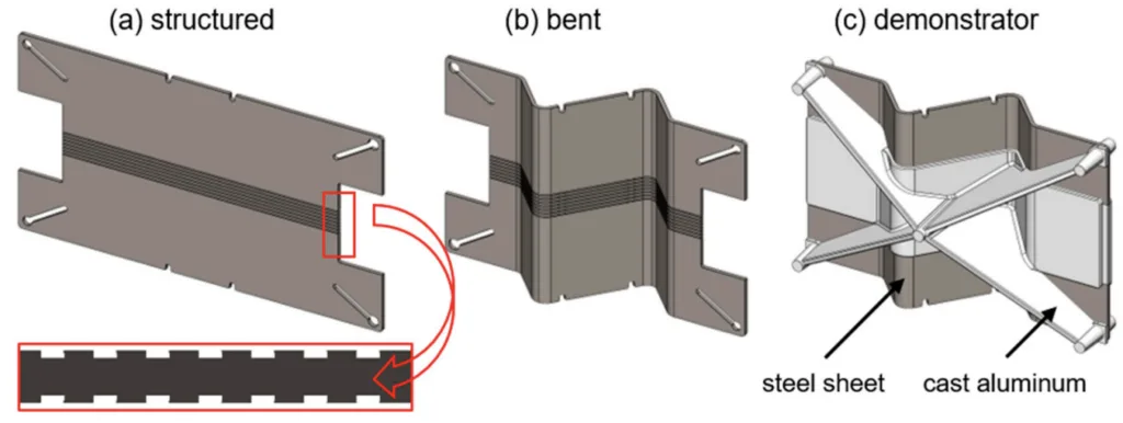

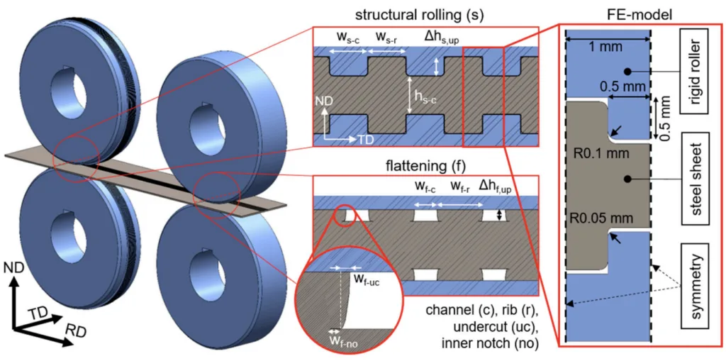

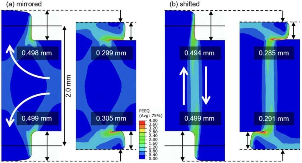

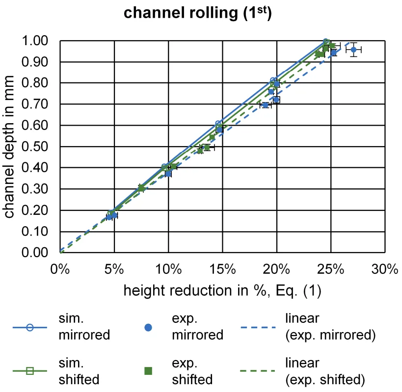
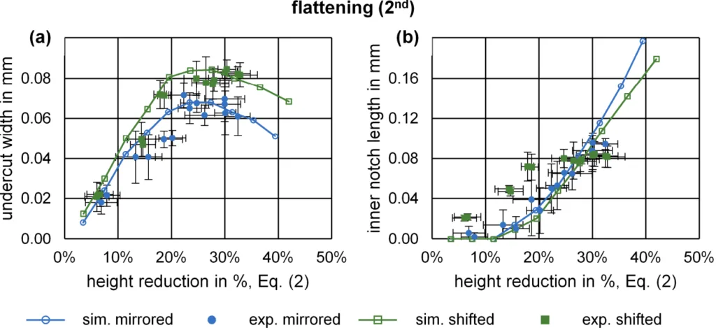
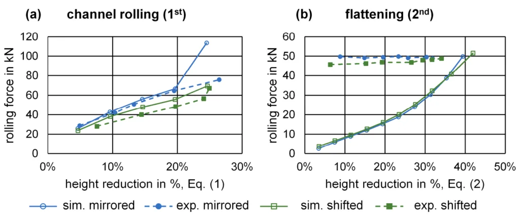
그림 이름 목록:
- Figure 1. Scheme of the rolling process for surface structures (as proposed by Senge et al. [15]); view in the normal direction (ND) and transverse direction (TD).
- Figure 2. Examples of surface structures on steel sheets after (a) rolling and cutting, (b) bending, and (c) casting of the demonstrator part.
- Figure 3. Investigated alignments of the double-sided surface structure.
- Figure 4. 3D scheme of the rolling process and 2D simplification in the FE simulation.
- Figure 5. Cross-section preparations of (a) structural rolling, mirrored, (b) flattening, mirrored, (c) structural rolling, shifted, (d) flattening, shifted.
- Figure 6. Exemplary material flow in FE simulations by equivalent plastic strain (PEEQ) after structural rolling and flattening.
- Figure 7. Close-up cross-section measurement examples of (a) structural rolling, mirrored, (b) flattening, mirrored, (c) structural rolling, shifted, (d) flattening, shifted.
- Figure 8. Channel depth after structural rolling for simulations vs. experiments of both alignments.
- Figure 9. (a) Undercut width and (b) inner notch length after flattening for simulations vs. experiments of both alignments.
- Figure 10. Max. rolling forces for (a) channel rolling and (b) flattening for simulations vs. experiments of both alignments.
7. 결론:
본 연구는 강판에 언더컷 특징을 생성하기 위한 양면 구조 압연 공정을 성공적으로 시뮬레이션하고 실험적으로 검증했습니다. 특히 평탄화 중 언더컷 폭에 대해 시뮬레이션과 실험 간에 좋은 일치가 달성되었습니다. 실험에서는 시트 가장자리에서 중간 채널에 비해 덜 이상적인 채널 형성이 나타났습니다. 대칭 배열은 시프트 배열에 비해 구조 압연 중 더 높은 압연 하중을 보였습니다. 반대로, 시프트 배열은 더 큰 언더컷(잠재적으로 접합 강도에 유리)을 생성했지만, 실험적으로 더 큰 내부 노치 경향을 보였고 판재를 사용한 실험 설정에서 상당한 롤러 마모를 유발했습니다. 배열 선택에는 장단점이 있습니다: 시프트 배열은 더 큰 언더컷과 낮은 구조 압연 하중을 제공하지만, 마모 및 내부 노치 형성을 증가시킬 수 있습니다. 향후 연구에서는 운동학 및 가이드 레일이 구조 균일성에 미치는 영향을 분석하고, HPDC 알루미늄과 결합된 시프트 배열 구조의 복합 강도를 테스트할 것입니다.
8. 참고 문헌:
- [1] Kim, H.C.; Wallington, T.J. Life-cycle energy and greenhouse gas emission benefits of lightweighting in automobiles: Review and harmonization. Environ. Sci. Technol. 2013, 47, 6089–6097. [CrossRef] [PubMed]
- [2] Cecchel, S. Materials and Technologies for Lightweighting of Structural Parts for Automotive Applications: A Review. SAE Int. J. Mater. Manf. 2021, 14, 81–97. [CrossRef]
- [3] Mori, K.; Abe, Y. A review on mechanical joining of aluminium and high strength steel sheets by plastic deformation. Int. J. Lightweight Mater. Manuf. 2018, 1, 1–11. [CrossRef]
- [4] Meschut, G.; Janzen, V.; Olfermann, T. Innovative and Highly Productive Joining Technologies for Multi-Material Lightweight Car Body Structures. J. Mater. Eng. Perform. 2014, 23, 1515–1523. [CrossRef]
- [5] Mori, K.; Bay, N.; Fratini, L.; Micari, F.; Tekkaya, A.E. Joining by plastic deformation. CIRP Ann. Manuf. Technol. 2013, 62, 673–694. [CrossRef]
- [6] Salamati, M.; Soltanpour, M.; Fazli, A.; Zajkani, A. Processing and tooling considerations in joining by forming technologies; part A—Mechanical joining. Int. J. Adv. Manuf. Technol. 2019, 101, 261–315. [CrossRef]
- [7] Feistauer, E.E.; dos Santos, J.F.; Amancio-Filho, S.T. A review on direct assembly of through-the-thickness reinforced metal-polymer composite hybrid structures. Polym. Eng. Sci. 2019, 59, 661–674. [CrossRef]
- [8] Noguchi, T.; Asano, K.; Hiratsuka, S.; Miyahara, H. Trends of composite casting technology and joining technology for castings in Japan. Int. J. Cast Met. Res. 2008, 21, 219–225. [CrossRef]
- [9] Fang, X.; Gundlach, J.; Schipperges, J.-J.; Jiang, X. On the Steel–Aluminum Hybrid Casting by Sand Casting. J. Mater. Eng. Perform. 2018, 27, 6415–6425. [CrossRef]
- [10] Ma, Y.; Zhang, G.; Cao, S.; Huo, Z.; Han, J.; Ma, S.; Huang, Z. A Review of Advances in Fabrication Methods and Assistive Technologies of Micro-Structured Surfaces. Processes 2023, 11, 1337. [CrossRef]
- [11] Müller, S.; Brand, M.; Dröder, K.; Meiners, D. Increasing the Structural Integrity of Hybrid Plastics-Metal Parts by an Innovative Mechanical Interlocking Effect. Mater. Sci. Forum 2015, 825–826, 417–424. [CrossRef]
- [12] Buxton, A.L.; Ferhati, A.; Glen, R.J.; Dance, B.G.I.; Mullen, D.; Karayiiannis, T. EB Surface Engineering for High Performance Heat Exchangers. In Proceedings of the First International Electron Beam Welding Conference, Chicago, Illinois, USA, 17–18 November 2009.
- [13] Ucsnik, S.; Gradinger, R.; Becirovic, A.; Waldhör, A. Enhanced Performance of Steel-Aluminium Cast Nodes through Cold Metal Transfer. Mater. Sci. Forum 2013, 765, 736–740. [CrossRef]
- [14] Abe, H.; Chung, J.C.; Mori, T.; Hosoi, A.; Jespersen, K.M.; Kawada, H. The effect of nanospike structures on direct bonding strength properties between aluminum and carbon fiber reinforced thermoplastics. Compos. Part B Eng. 2019, 172, 26–32. [CrossRef]
- [15] Senge, S.; Brachmann, J.; Hirt, G.; Bührig-Polaczek, A. Interlocking Multi-Material Components made of Structured Steel Sheets and High-Pressure Die Cast Aluminium. In Proceedings of the 20th International ESAFORM Conference on Material Forming, Dublin, Ireland, 26–28 April 2017; p. 190007.
- [16] Senge, S.; Brachmann, J.; Hirt, G.; Bührig-Polaczek, A. Evaluation of interlocking bond strength between structured 1.0338 steel sheets and high pressure die cast AlMg5Si2. In Proceedings of the 21st International ESAFORM Conference on Material Forming, Palermo, Italy, 23–25 April 2018; p. 40019.
- [17] Ringel, A.; Lohmar, J. Optimization of the Surface Geometry in Structured Cold Rolling for Interlocking of Formed and Die-Cast Metal Components. Defect Diffus. Forum 2022, 414, 89–94. [CrossRef]
- [18] Jakumeit, J.; Behnken, H.; Laqua, R.; Eiken, J.; Brachmann, J. Multi-scale simulation of hybrid light metal structures produced by high pressure die casting. IOP Conf. Ser. Mater. Sci. Eng. 2020, 861, 12035. [CrossRef]
- [19] Joop, D. Präzisionsbestimmende Faktoren bei der Herstellung blechverstärkter Hybridstrukturen im Druckguss: Grenzflächenanalyse und Verzugsoptimierung. Doctoral Thesis, Gießerei-Institut, RWTH Aachen University, Aachen, Germany, 2018.
- [20] Ringel, A.; Hirt, G. Bending behavior of structured steel sheets with undercuts for interlocking with Al die-cast metal. Int. J. Mater. Form. 2024, 17, 2. [CrossRef]
- [21] Bruckmeier, L.; Ringel, A.; Vroomen, U.; Bailly, D.; Bührig-Polaczek, A. Influence of High-Pressure Die Casting Process Parameters on the Compound Strength of Hybrid Components with Undercut Sheet Metal. Metals 2023, 13, 1717. [CrossRef]
- [22] Tieu, A.; Liu, Y. Friction variation in the cold-rolling process. Tribol. Int. 2004, 37, 177–183. [CrossRef]
- [23] Clausmeyer, T.; Schowtjak, A.; Wang, S.; Gitschel, R.; Hering, O.; Pavliuchenko, P.; Lohmar, J.; Ostwald, R.; Hirt, G.; Tekkaya, A.E. Prediction of Ductile Damage in the Process Chain of Caliber Rolling and Forward Rod Extrusion. Procedia Manuf. 2020, 47, 649–655. [CrossRef]
9. 저작권:
- 본 자료는 "Aron Ringel, Sindokht Shayan and David Bailly"의 논문입니다. "Double-Sided Surface Structures with Undercuts on Cold-Rolled Steel Sheets for Interlocking in Hybrid Components"를 기반으로 합니다.
- 논문 출처: https://doi.org/10.3390/machines12080562
본 자료는 상기 논문을 바탕으로 요약되었으며, 상업적 목적의 무단 사용을 금지합니다.
Copyright © 2025 CASTMAN. All rights reserved.