본 소개 자료는 "Technische Universität Darmstadt"에서 발표한 "[Influence of Zr, Cr and Sc alloying on the microstructure and mechanical properties of a Al-Mg-Si casting alloy]" 논문을 바탕으로 작성되었습니다.
1. 개요:
- 제목: Influence of Zr, Cr and Sc alloying on the microstructure and mechanical properties of a Al-Mg-Si casting alloy
- 저자: Prach Olena, M.Sc.
- 발행 연도: 2021
- 발행 학술지/학회명: Technische Universität Darmstadt
- 키워드: Al-Mg-Si casting alloy, Zirconium, Chromium, Scandium, Microstructure, Mechanical properties, High-Pressure Die Casting (HPDC)
2. 초록:
본 연구에서는 Sc, Cr, Zr이 첨가된 새로운 Al-Mg-Si-Mn 주조 합금을 개발하고, 미세조직과 함께 기계적 특성을 연구했습니다. Al-Mg-Si-Mn 합금의 시차 주사 열량 분석(DSC) 연구를 통해 공정 용융 온도가 595°C임을 확인했으며, Cr, Zr, Sc 첨가는 합금의 응고 거동을 변화시키지 않았습니다. Cr, Zr, Sc의 미량 첨가는 미세조직을 본질적으로 변화시키지 않았으며, 주로 α-Al과 α-Al15(Mn,Fe)3Si2 상으로 구성되었으나 층간 간격을 약간 변화시켰습니다. Sc 미함유 합금에서는 Al3Zr 및 Al7Cr 금속간 화합물이 관찰되었고, Sc 함유 합금에서는 Al3Sc 및 Al3Zr 상이 관찰되었습니다. Zr, Cr, Sc는 주로 고용체를 강화시켰습니다. 미세경도 및 나노경도 측정 결과, 합금 그룹 내에서 일관된 경향을 보였습니다. Zr 또는 Zr+Cr 첨가는 기본 합금에 비해 항복 강도 및 인장 강도를 크게 증가시키지 않았으나, Sc 첨가는 인장 특성을 현저히 증가시켰습니다. SZ11 합금(Sc+Zr)은 S2(Sc 단독) 합금과 유사한 결과를 보였습니다. 주조 상태에서 인공 시효 처리(T5)는 기본 합금에서 석출 경화를 유도하지 않았습니다. Sc 미함유 합금은 225°C에서 T5 처리에 가장 잘 반응한 반면, Sc 함유 합금은 325°C에서 나노 분산된 Al3Sc 석출물로 인해 가장 큰 이점을 얻었습니다. 고온 용체화 처리(T6)는 섬유상 공정상의 구상화를 초래하여 강도를 저하시키고 연성을 증가시켰습니다. 예상외로, HPDC 합금은 T6 처리에서 연성 측면에서 긍정적인 반응을 보였습니다.
3. 서론:
경량 알루미늄 합금은 운송 부문에서 에너지 절약 및 연료 효율성 향상을 위해 점점 더 중요해지고 있습니다. Al-Mg-Si 단조 합금(6xxx 계열)은 석출 경화를 통해 우수한 강도 잠재력을 가지므로 널리 사용됩니다. Al-Si 주조 합금이 알루미늄 주물의 90% 이상을 차지하는 반면, Al-Mg-Si 주조 합금은 덜 일반적이지만 우수한 주조성, 내식성 및 주조 상태에서의 기계적 특성으로 인해 자동차 및 항공 우주 분야에서 주목받고 있습니다.
본 논문의 목적은 상용 합금 Magsimal®59의 기계적 특성을 Sc, Cr, Zr 합금화를 통해 개선하는 것입니다. 스칸듐 첨가는 Al3Sc 석출물 형성 및 결정립 미세화를 통해 강도를 크게 향상시키는 것으로 알려져 있지만, 높은 비용으로 인해 사용이 제한적입니다. 지르코늄은 작업성을 향상시키고 저렴하며, 크롬은 결정립 구조 제어 및 인성 향상에 사용됩니다.
주요 목표는 Sc, Zr, Cr을 함유한 Al-Mg-Si 합금에 대한 지식을 증진하고, Sc 및 Zr 단독 첨가가 Al-Mg-Si 합금의 미세조직과 특성에 미치는 영향을 조사하며, 유사한 기계적 특성 및 석출 거동을 얻기 위해 Zr 및/또는 Cr로 Sc를 완전 또는 부분적으로 대체할 가능성을 탐색하는 것입니다.
4. 연구 요약:
연구 주제의 배경:
알루미늄 합금은 다양한 산업, 특히 운송 부문에서 경량화를 통해 연료 소비와 배기가스 배출을 줄이는 데 중요합니다. 열처리성과 우수한 특성 균형으로 알려진 Al-Mg-Si 합금은 주로 단조 제품으로 사용됩니다. 그러나 복잡한 형상 제조 능력과 우수한 기계적 성능을 결합하기 위해 고성능 Al-Mg-Si 주조 합금, 특히 고압 다이캐스팅(HPDC)용 합금 개발에 대한 관심이 증가하고 있습니다. Zr, Cr, Sc와 같은 원소로 미세 합금화하여 이러한 합금을 최적화하면 미세조직과 기계적 특성을 향상시킬 수 있습니다.
이전 연구 현황:
이전 연구에서는 Magsimal®59, Hydronalium 511, Aural11과 같은 상용 주조 합금을 포함하여 Al-Mg-Si 계의 이점을 확립했으며, 이들 합금은 주조 상태에서 우수한 기계적 특성을 제공합니다. Sc(상당한 강화, 결정립 미세화), Zr(작업성 향상, Al3Zr 석출물), Cr(결정립 구조 제어, 인성)의 개별 첨가가 알루미늄 합금에 미치는 영향은 주로 단조 합금 또는 다른 Al 합금 계에 대한 연구를 통해 알려져 있습니다. 그러나 이러한 원소의 조합 첨가, 특히 Sc 대체에 초점을 맞춘 Al-Mg-Si 주조 합금, 특히 HPDC 변형에 대한 포괄적인 연구는 제한적입니다. 이러한 복잡한 다성분 합금의 상 형성을 이해하기 위해서는 열역학적 모델링 및 상태도 계산이 중요합니다.
연구 목적:
본 연구의 주요 목표는 상용 Al-Mg-Si 주조 합금(Magsimal®59)의 기계적 특성을 스칸듐(Sc), 지르코늄(Zr), 크롬(Cr)의 체계적인 합금화를 통해 개선하는 것입니다. 구체적인 목표는 다음과 같습니다:
- Sc, Zr, Cr의 개별 및 조합 첨가가 Al-Mg-Si 기본 합금의 미세조직 및 기계적 특성에 미치는 영향을 조사합니다.
- 기계적 성능을 유지하거나 향상시키면서 고가의 스칸듐을 보다 경제적인 지르코늄 및/또는 크롬으로 부분적 또는 전체적으로 대체할 가능성을 탐색합니다.
- 주조 상태 및 열처리 상태 모두에서 새로 개발된 합금의 석출 거동 및 강화 메커니즘을 이해합니다.
핵심 연구:
본 연구의 핵심은 Magsimal®59 조성을 기반으로 Zr, Cr, Sc를 개별적으로 또는 조합하여 체계적으로 첨가한 새로운 Al-Mg-Si-Mn 주조 합금의 개발 및 조사입니다. 이들 합금은 고압 다이캐스팅(HPDC)으로 생산되었습니다. 본 연구는 다음에 중점을 두었습니다:
- 미세조직 특성화: 시차 주사 열량계(DSC), 광학 현미경, 에너지 분산형 X선 분광법(EDS)을 갖춘 주사 전자 현미경(SEM), 투과 전자 현미경(TEM)을 사용하여 주조 상태 및 열처리 상태의 미세조직을 포괄적으로 분석했습니다. 여기에는 구성상, 금속간 화합물(예: Al15(Mn,Fe)3Si2, Al3Zr, Al7Cr, Al3Sc), 공정 조직(Mg2Si) 형태, 수지상정 간격(DAS) 및 층간 간격(ILS) 식별이 포함됩니다.
- 기계적 특성 평가: 주조 상태 및 다양한 열처리 상태(T5 및 T6 처리)에서 미세경도, 매크로경도(브리넬), 나노경도(α-Al 기지 및 공정 영역, 금속간 화합물), 인장 특성(항복 강도, 극한 인장 강도, 연신율)을 평가했습니다.
- 열처리 반응: 다양한 인공 시효(주조 상태에서 125-325°C의 T5) 및 용체화 처리 후 인공 시효(T6 처리, 가스 방출 현상 연구 포함) 열처리에 대한 합금의 반응을 조사했습니다.
- 열역학적 계산: Thermo-Calc 소프트웨어를 사용하여 상태도를 계산하고 개발된 다성분 합금의 상 형성을 예측했습니다.
5. 연구 방법론
연구 설계:
본 연구는 합금 원소 Zr, Cr, Sc가 기본 Al-Mg-Si-Mn 합금(상용 Magsimal®59)에 미치는 영향을 체계적으로 조사하도록 설계되었습니다. 이러한 원소의 농도를 다양하게 하여 개별적으로 또는 조합하여 일련의 실험 합금이 개발되었습니다(세부 사항은 Table 3.6 참조). 모든 합금은 산업 적용과 관련된 조건을 보장하기 위해 고압 다이캐스팅(HPDC)을 사용하여 생산되었습니다. 본 연구는 개발된 합금을 주조 상태 및 다양한 열처리 조건(T5 및 T6)에서 기본 합금과 비교했습니다.
데이터 수집 및 분석 방법:
- 주조: 합금은 Frech DAK 450-54 냉가압식 HPDC 장비를 사용하여 제조되었습니다. 첨가에는 모합금(AlCr20, AlZr15, AlSc2)이 사용되었습니다.
- 화학 분석: 조성 제어를 위한 스파크 방출 분광법(Ametek Spectromaxx).
- 시차 주사 열량계(DSC): NETZSCH 장치를 사용하여 상변태 온도(예: 용융, 응고)를 결정했습니다.
- 미세조직 특성화:
- 광학 현미경 및 주사 전자 현미경(SEM - TESCAN Mira3)과 에너지 분산형 X선 분광법(EDS)을 사용하여 ImageJ 소프트웨어로 상 식별, 형태, 분포, 수지상정 간격(DAS) 및 층간 간격(ILS)을 분석했습니다.
- 전자 탐침 미세분석(EPMA - JEOL JXA-8100)을 사용하여 상세한 원소 매핑을 수행했습니다.
- 투과 전자 현미경(TEM - Philips CM20)을 사용하여 미세 석출물 및 분산상을 관찰했습니다.
- 기계적 시험:
- 경도: 브리넬 경도, 비커스 미세경도(Zwick Roell), 나노인덴테이션(iNano, G200, Berkovich 팁 사용, LC 및 CSM 모드).
- 인장 시험: ASTM E8_E8M_13a 규격에 따라 Instron 5967 장비에서 실온 단축 인장 시험을 수행했습니다.
- 열처리: T5(주조 상태에서 인공 시효 처리, 125°C, 175°C, 220°C, 325°C) 및 T6(용체화 처리, 480-570°C, 수냉, 이후 175°C, 225°C, 325°C에서 인공 시효 처리). 용체화 처리 중 가스 방출 효과도 연구되었습니다.
- 열역학적 계산: Thermo-Calc 소프트웨어(TCAl2: Al-alloys v2.1 데이터베이스)를 사용하여 상태도를 계산하고 상 형성을 예측했습니다.
연구 주제 및 범위:
본 연구는 Zr(0.1-0.2 wt.%), Cr(0.1-0.3 wt.%), Sc(0.1-0.2 wt.%) 및 이들의 조합(예: Cr+Zr, Sc+Zr)을 첨가하여 변형한 Magsimal®59 기본 조성의 Al-Mg-Si-Mn 주조 합금에 중점을 두었습니다. 범위는 다음과 같습니다:
- DSC를 사용한 상변태 및 응고 거동 조사.
- 주조 상태에서의 상세한 미세조직 분석(존재하는 상, 형태, 크기, 분포, 원소 편석). 식별된 상에는 α-Al, Mg2Si 공정상, α-Al15(Mn,Fe)3Si2, Al3Zr, Al7Cr, Al3Sc가 포함됩니다.
- DAS, ILS 및 상의 부피 분율과 같은 미세조직 특징 정량화.
- 주조 상태에서의 기계적 특성 평가(다양한 경도 스케일, 인장 강도, 항복 강도, 연신율).
- 열처리 반응 연구:
- T5 시효: 시효 동역학 및 경도 및 인장 특성에 미치는 영향.
- T6 처리: 용체화 처리 온도가 가스 방출, 미세조직 및 이후 시효 반응이 경도 및 인장 특성에 미치는 영향.
- 미세조직과 기계적 특성의 상관관계.
- Zr 및/또는 Cr에 의한 Sc 대체 가능성 평가.
6. 주요 결과:
주요 결과:
주조 상태:
- DSC: Al-Mg-Si-Mn 합금의 공정 용융 온도는 약 595°C로 결정되었습니다. Cr, Zr, Sc의 첨가(단독 또는 이중)는 합금 응고 거동을 크게 변경하지 않았습니다.
- 미세조직: 주요 상은 α-Al(등축정, 구상-로제트 형태, DAS 약 10-12 µm)과 α-Al15(Mn,Fe)3Si2였습니다. Cr, Zr, Sc 첨가는 Mg2Si 공정상의 층간 간격(ILS)을 약간 변화시켰습니다.
- Sc 미함유 합금: Zr/Cr 함량에 따라 Al3Zr(Z2에서 직교형, 약 13 µm) 및 Al7Cr 금속간 화합물이 관찰되었습니다.
- Sc 함유 합금: Al3Sc(불규칙한 형태, α-Al15(Mn,Fe)3Si2 부근)가 특히 S2(0.2 wt.% Sc)에서 관찰되었습니다. Zr 첨가 시 Al3Zr 상도 존재했습니다(예: SZ11, SZ21, SZ21에서 더 큰 Al3Zr).
- Zr, Cr, Sc는 주로 고용체를 강화시켰습니다. Mn과 Cr은 부분적으로 초정 입자에 존재하고 부분적으로 고용체에 존재했습니다.
- 경도: 동일한 주 합금 원소를 가진 합금 내에서(예: Z1-Z2, S1-S2), 평균 미세경도 및 나노경도는 유사했습니다. Sc 함유 합금은 일반적으로 더 높은 경도를 보였습니다. Zr 또는 Zr+Cr 첨가는 기본 M59에 비해 매크로/미세 경도를 크게 증가시키지 않았습니다. Sc 및 Sc+Zr 첨가는 가장 높은 매크로경도를 나타냈습니다(예: SZ21 및 SCZ는 M59보다 약 15% 더 단단함). α-Al 및 공정 영역의 나노경도는 합금화에 따라 증가했으며, Sc 및 Sc+Zr 첨가가 가장 높은 공정 경도를 보였습니다.
- 인장 특성: Zr 또는 Zr+Cr 첨가는 항복 강도를 크게 증가시키지 않았습니다. Sc 합금화는 인장 특성(YS, UTS, 연신율)을 현저히 증가시켰습니다. 0.1 wt.% Sc는 고용체 강화에 충분했으며, 추가 Sc 첨가는 더 이상의 강화로 이어지지 않았습니다. SZ11 합금(Sc+Zr)은 S2(Sc 단독) 합금과 유사한 인장 결과를 보였습니다.
열처리 상태:
- T5 시효 처리(주조 상태에서):
- 기본 합금(M59)은 상당한 석출 경화를 나타내지 않았습니다.
- Sc 미함유 합금은 225°C에서 양호한 반응을 보였습니다.
- Sc 함유 합금은 325°C에서 가장 큰 이점을 보였으며, 나노 분산된 Al3Sc 석출물이 관찰되었습니다(예: 225°C/325°C에서 시효 처리된 S1, S2 합금).
- S2 합금(0.2 wt.% Sc)은 325°C에서 가장 높은 YS 및 UTS를 달성했습니다.
- T6 처리(용체화 처리 + 시효):
- 고온 용체화 처리(ST > 520°C)는 섬유상 Mg2Si 공정상의 구상화를 초래하여 인장/항복 강도를 크게 저하시키지만 연성을 증가시켰습니다.
- 기본 합금의 경우 ST 온도 ≥ 520°C에서 가스 방출(블리스터링)이 관찰되었습니다.
- ST 후 경도는 주조 상태보다 낮았지만 시효 후 증가했습니다.
- 기본 합금의 경우 T6(ST 570°C + AA 175°C) 처리 시 T5와 유사한 경도를 나타냈으며, YS는 164 MPa(주조 상태)에서 200 MPa로 증가했습니다. S2 합금의 경우 YS는 194 MPa(주조 상태)에서 220 MPa로 증가했습니다. 고온 ST 온도에서의 블리스터링으로 인해 T6 후 연신율은 일반적으로 주조 상태에 비해 낮았습니다.
- 낮은 ST 온도(예: 480°C)는 Mg2Si를 효과적으로 용해시키지 못하여 시효 반응이 좋지 않았습니다.
- Al3Zr, Al3Sc, Al7Cr 초정 금속간 화합물은 520°C의 ST에 의해 크게 영향을 받지 않았습니다.
- 비교: HPDC 합금은 블리스터링을 제어할 수 있다면 T6 처리에서 연성 측면에서 예상치 못한 긍정적인 반응을 보였습니다. T5 처리, 특히 Sc 함유 합금의 경우 325°C에서 상당한 강도 향상을 제공했습니다. Al3Sc와 Mg2Si 석출 경화의 조합은 열처리 최적화를 위한 복잡한 시나리오를 제공합니다.
![Figure 2.5 Graphical illustration of a) hot-chamber, b) cold-chamber die casting
machine[32]](https://castman.co.kr/wp-content/uploads/image-2222-1024x447.webp)
![Figure 2.6 a) Structural zone formation in castings [36], b) dendritic arms [36], c) SEM image of dendrites in Al-Mg-Si alloys (present work), d) SEM image of aluminum dendrites in the fractured surface of a tensile test bar of the Al-MgSi alloy (present work).](https://castman.co.kr/wp-content/uploads/image-2223-1024x880.webp)
![Figure 6.17 Microstructure of the AlMg5Si2Mn HPDC alloy and 3D modelling of theMg2Si eutectic in the a)as-cast and b,c) heat-treated state. From [171]](https://castman.co.kr/wp-content/uploads/image-2224-1024x540.webp)
그림 목록:
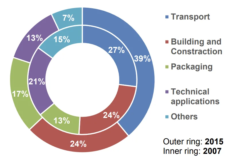
- Figure 2.1 Fields of the application of Al alloys in 2007 and 2015 as for comparison, adapted from [22].
- Figure 2.2 World aluminum production, adopted from [18].
- Figure 2.3 Semi-product of aluminum alloys, adapted from [22].
- Figure 2.4 Classification of the casting techniques. Adopted from [31]
- Figure 2.5 Graphical illustration of a) hot-chamber, b) cold-chamber die casting machine[32]
- Figure 2.6 a) Structural zone formation in castings [36], b) dendritic arms [36], c) SEM image of dendrites in Al-Mg-Si alloys (present work), d) SEM image of aluminum dendrites in the fractured surface of a tensile test bar of the Al-Mg-Si alloy (present work).
- Figure 2.7 SEM image of the Al-Mg-Si-Sc-Zr alloy with the EDX maps of Mg, Si, Sc, Zr and composition vs distance along the line [45].
- Figure 2.8 Morphology of the Mg2Si eutectic in the a) as-cast Al-Mg2Si alloy and b) after solution treatment at 575°C [49].
- Figure 2.9 Schematic representation of a strengthening mechanisms in Al. Adopted from [50]
- Figure 2.10 Different types of solid solutions a) Substitutional and b) interstitial solid solution. Adapted from [55].
- Figure 2.11 Crystallographic relationships between matrix and second phase. a) coherency with strained, but continuous, lattice planes across the boundary, b) semicoherent, c) incoherent equilibrium precipitate. Adapted from [54,66]
- Figure 2.12 Schematic illustration of interaction mechanisms between dislocations and precipitates: particle looping and particle cutting. Adapted from [71].
- Figure 2.13 Strength vs size of particles, adopted from [50,51].
- Figure 3.1 a)Ternary Al-Mg-Si diagram with the pseudobinary line (red) and an experimentally established an invariant line of L → (Al) + Mg2Si (black curved line), b) binary Al-Mg2Si phase diagram, showing an influence of excess Mg [94] and c) Al-Mg-Si Liquidus surface [88].
- Figure 3.2 Binary phase diagram a) Al-Mg2Si, the investigated alloy is marked with arrow, adapted from [87] and b) calculated Al-5Mg-2Si-(0…2.0)Mn phase diagram.
- Figure 3.3 a) Al-Sc phase diagram [120], b) Al-rich side of Al-Sc diagram calculated by Thermo-Calc.
- Figure 3.4 Scheme of the L12-type structure of Al3Sc precipitates
- Figure 3.5 a) SEM image of Al3Sc particle found in Al-2Sc master alloy [123], b) TEM bright-field image of the Al3Sc particle in Al-0.7Sc alloy [116] and c) TEM bright-field image of Al3Sc precipitates [111].
- Figure 3.6 a) Al-rich side of Al-Zr diagram and b) variety of the crystal structures [130].
- Figure 3.7 TEM images of a) bright and b) dark-field of Al-Mg-Si-Zr wrought alloy after annealing [111]
- Figure 3.8 Bright field TEM images of the Al3(Sc,Zr) nanoparticles, a) [114], b) [135], c) [128]
- Figure 3.9 Calculated phase diagrams of the investigated alloys, AlMg5Si2Mn with additions of a)Zr, b) Cr and Zr
- Figure 3.10 Phase diagrams of the investigated alloys, AlMg5Si2Mn with additions of a) Sc, b) Sc and Zr, c )Sc, Cr and Zr.
- Figure 3.11 a) Typical temperature regions for solution heat treatment and precipitation hardening [13] and b) Precipitation sequence of the investigated alloys, adapted from [50]
- Figure 4.1 a) As-caste plate with gating system and overflow directly after withdrawing from the HPDC machine and b) after removal of the casting system.
- Figure 4.2 a) Schematic illustration of the indentation imprint and its diagonals measurement and b) Image of a microhardness imprint on a polished surface
- Figure 4.3 Schematic illustration of a load displacement curve
- Figure 4.4 Schematic illustration of the tensile test samples
- Figure 5.1 DSC curve of the base alloy in as-cast state.
- Figure 5.2 a) DSC heating and cooling curves of the Sc free alloys, b) enlarged DSC traces for these alloys in a range of 590-600°C.
- Figure 5.3 DSC heating and cooling curves of the Sc containing alloys
- Figure 5.4 Cross section of the plate with the corresponding microstructures.
- Figure 5.5 SEM image of a base alloy: a) an overview of a microstructure, b) Mn- containing intermetallic phase.
- Figure 5.6 SEM image of the base alloy and EMPA maps of the dendritic area
- Figure 5.7 SEM micrographs of the Sc free alloys
- Figure 5.8 EMPA maps of the distribution of the Zr in a)Z1 alloy and b) Z2 alloy
- Figure 5.9 EMPA maps of the distribution of the Zr and Cr in a)CZ11 alloy and b) CZ12 alloy
- Figure 5.10 SEM micrographs of the Sc-containing alloys
- Figure 5.11 SEM images and EMPA maps of the dendritic area of a) S1, b) S2 alloys in as-cast state
- Figure 5.12 SEM images and EMPA maps of the dendritic area of a) SZ11, b) SZ21 alloys in as-cast state
- Figure 5.13 SEM image of the Mn-containing phase in the base alloy. a) polished sample, b) fracture surface and c) Mn-containing phase in Sc-containing alloy.
- Figure 5.14 SEM images of the alloys with coarse Cr-, Zr- containing phases [159]
- Figure 5.15 SEM micrograph and EDS elemental mapping of the Al7Cr and Al3Zr intermetallic phases in the CZ33 alloy [159].
- Figure 5.16 TEM bright-field images of the a-c) base alloy with the β and β' precipitates in the base alloy.
- Figure 5.17 TEM bright-field images of the a- b) Mn-containing dispersoids in the base alloy and Al3Sc precipitates observed in b)S1 and c)S2 alloys
- Figure 5.18 a) Cross section of the plate and b) volume fraction of the α-Al and eutectic close to the edge region and in the middle part of the plate, ILS for the middle region plotted for M59, Z2 and S2 alloys.
- Figure 5.19 a) Macro- and b) micro-hardness of the Sc-free alloys and Sc-containing alloys in as-cast state
- Figure 5.20 Microstructure of investigated alloy with indent in a) α-Al matrix and b) eutectic as an example, nanohardness measurements of the c) α-Al matrix and eutectic.
- Figure 5.21 Images of the α-Al15(Mn,Fe)3Si2 intermetallic phase with the corresponding load-displacement and hardness-displacement curves.
- Figure 5.22 Images of the a) Al7Cr and b) Al3Zr intermetallic phases with the corresponding hardness-displacement curves.
- Figure 5.23 Load–displacement and hardness-displacement curves for the α- Al15(Mn,Fe)3Si2, Al3Zr and Al7Cr primary phases.
- Figure 5.24 Tensile properties of the investigated alloys a) yield strength b) ultimate tensile stress and c) elongation to failure in as-cast state.
- Figure 5.25 Typical SEM morphology of the fracture surface of the as-cast alloys processed by HPDC, a) macroscopic fracture of the tensile bar for the base alloy, b) pores on the fracture surface for the base alloy, c) the enlarged fracture surface of the Sc-free alloy Al3Zr and Al7Cr intermetallics in the d) CZ22 and e) SZ12 alloys.
- Figure 5.26 Effect of the change in the interlamellar space on the a) yield strength and b) elongation.
- Figure 6.1 Microhardness as a function of a time at a) 125, b) 175, c) 225 and d) 325°C.
- Figure 6.2 Tensile properties of the a) base alloy (black line) and Z2 (blue line), b) S2 (green line) as a function of aging temperature for 3hours.
- Figure 6.3 Tensile properties as a function of aging time after AA at 325°C.
- Figure 6.4 Tensile properties as a function of chemical composition after 3 hours of AA a) 225°C b) 325°C
- Figure 6.5 Tensile properties as a function of artificial aging for 3 hours at 225°C and 325°C a-b) yield stress, c-d) ultimate tensile stress and e-f) elongation to failure.
- Figure 6.6 TEM bright-field images of the M59 alloy after artificial aging a-b) at 175ºC; c-d) at 325ºC
- Figure 6.7 TEM bright-field images of the Sc-containing alloys after artificial aging: a) S1 after 225ºC, b) S1 325ºC, c) S2 225ºC, d) S2 325ºC
- Figure 6.8 a) Hardness across the plate after the heat treatment and as-cast state. AA at 175°C (24 hours) and b) surface tensile samples of the base alloy and after different solution-treatment schedules.
- Figure 6.9 Structure after solution treatment at different temperatures during 1h [172].
- Figure 6.10 Hardness-time curves for the base alloy aged at 175°C following the solution treatment procedures at 570 and 480°C. The black curve represents results after AA directly from as-cast state.
- Figure 6.11 Microstructure of the M59 alloy in a) as-cast state and after solution treatment at b) 480°C, c) 520°C, d) 570°C.
- Figure 6.12 SEM images of the a) Z2, b) S2 and c) CZ33 alloys after ST at 520°C during 3h [172].
- Figure 6.13 Stress-strain curves for the base and S2 alloys after high temperature T6 regime (ST570°C+AA175°C).
- Figure 6.14 Tensile properties as a function of chemical composition after ST520+AA225 and ST520+AA325 (marked with red symbols).
- Figure 6.15 TEM bright-field images taken along 〈001〉Al axis of the M59 alloy after the solution treatment without aging at a-b) 520 ºC and c-d) 570ºC*.
- Figure 6.16 TEM bright-field images taken along 〈001〉Al axis showing the Al3Zr dispersoids in Z2 alloy after solution treatment Z2 alloy at 520ºC during 1.5h
- Figure 6.17 Microstructure of the AlMg5Si2Mn HPDC alloy and 3D modelling of theMg2Si eutectic in the a)as-cast and b,c) heat-treated state. From [171]
- Figure 6.18 Comparative stress strain curves for the base alloy and S2 alloy after T6 regime and in as-cast state (dashed lines).
- Figure 6.19 Tensile properties of the M59, Z2 and S2 alloys after different heat treatment regimes.
- Appendix A.1 Casting cycle for cold-chamber die casting [32] (부록 그림)
- Appendix A.5 SEM-images of the base alloy after artificial aging at a) 175ºC and b) 325 ºC [SC31]. (부록 그림)
- Appendix A.6 Comparative stress-strain curves for the a) alloys with a single addition and b-c) with combined additions in the as-cast state. (부록 그림)
7. 결론:
본 연구는 Sc, Cr, Zr을 첨가한 새로운 Al-Mg-Si-Mn 주조 합금을 성공적으로 개발하고 그 미세조직과 기계적 특성을 규명했습니다.
주조 상태:
- 공정 용융 온도는 미량 합금 원소 첨가에 영향을 받지 않고 지속적으로 약 595°C였습니다.
- 미세조직은 α-Al, Mg2Si 공정상, α-Al15(Mn,Fe)3Si2 상으로 구성되었습니다. Sc 미함유 합금은 Al3Zr 및 Al7Cr을 형성할 수 있었고, Sc 함유 합금은 Al3Sc 및 Al3Zr을 형성했습니다. 이러한 첨가는 층간 간격을 약간 변화시켰습니다.
- Zr, Cr, Sc 첨가는 주로 고용체를 강화시켰습니다.
- 경도(미세, 나노)는 합금 그룹 내에서 일관되었으며, Sc 함유 합금이 일반적으로 더 단단했습니다.
- Zr 또는 Zr+Cr 첨가는 기본 합금에 비해 항복/인장 강도를 크게 향상시키지 못했습니다. 그러나 Sc 첨가는 인장 특성을 현저히 증가시켰습니다. SZ11(Sc+Zr) 합금은 S2(Sc 단독) 합금과 유사한 성능을 보여 Sc 대체 가능성을 시사했습니다.
열처리 상태:
- 주조 상태에서 기본 합금의 인공 시효(T5)는 석출 경화를 유도하지 않았습니다.
- Sc 미함유 합금은 225°C에서 T5에 잘 반응한 반면, Sc 함유 합금은 325°C에서 T5로부터 가장 큰 이점을 얻어 나노 분산된 Al3Sc 석출물을 형성했습니다.
- T6의 초기 단계(고온 용체화 처리)는 섬유상 공정상의 구상화를 야기하여 강도를 저하시키고 연성을 증가시켰습니다. 기본 합금의 완전한 T6 처리는 기계적 특성에서 큰 개선을 보이지 않았습니다.
- 예상외로, HPDC 합금은 T6 처리에서 연성 측면에서 긍정적인 반응을 보였습니다.
전반적으로 Sc 또는 Sc와 Zr의 조합 합금화는 Al-Mg-Si HPDC 합금의 기계적 특성을 크게 향상시킵니다. 특정 열처리(T5 대 T6)는 원하는 강도와 연성의 균형에 따라 선택해야 하며, 고온(예: Sc 합금의 경우 325°C)에서의 T5는 강도에 유망하고, T6는 잠재적으로 연성에 유망합니다.
8. 참고문헌:
- [References] (논문의 참고문헌 목록 전체를 여기에 포함합니다. 예시는 생략합니다.)
9. 저작권:
- 본 자료는 "Prach Olena, M.Sc."의 논문입니다. "Influence of Zr, Cr and Sc alloying on the microstructure and mechanical properties of a Al-Mg-Si casting alloy"에 기반합니다.
- 논문 출처: urn:nbn:de:tuda-tuprints-172138
본 자료는 상기 논문을 바탕으로 요약되었으며, 상업적 목적의 무단 사용을 금합니다.
Copyright © 2025 CASTMAN. All rights reserved.