1. 개요:
- 제목: Three-Phase 75 kW Brushless Direct Current Motor for Electric Vehicles: Different Power Stage Design, Calculation of Losses, Cooling Techniques, and Comparison
- 저자: Ali Bahadir, Omer Aydogdu, Elif Bahadir
- 발행 연도: 2024
- 발행 학술지/학회: Applied Sciences
- Keywords: brushless DC motor, electric vehicles (EV), power stage, cooling system, losses
2. 연구 배경:
기후 변화로 인한 CO2, SO2 배출량 감소의 필요성이 증대되고 있으며, 이를 위해 전기 자동차의 효율 증대가 중요해졌다. BLDC 모터는 전기 자동차에 널리 사용되지만, 높은 내부 발열과 비효율적인 열 방출로 인해 신뢰성과 수명이 제한된다. 따라서 전기 모터 손실 감소 및 효율 향상을 위한 연구가 필수적이다. 기존 연구는 배터리 또는 모터 냉각에만 집중하였으며, 냉각 시스템의 에너지 소비량을 고려하지 않았다는 한계가 있다.
3. 연구 목적 및 연구 질문:
- 연구 목적: 75kW BLDC 모터를 위한 전력 시스템 설계, 손실 계산, 냉각 시스템 설계 및 비교를 통해 전기 자동차의 효율성을 높이는 것을 목적으로 한다.
- 핵심 연구 질문: 세 가지 다른 전력 단계 설계와 냉각 시스템(공냉, 팬 보조 공냉, 액냉)의 성능을 어떻게 비교할 수 있을까? 각 냉각 시스템의 효율과 손실을 어떻게 정량화할 수 있을까?
- 연구 가설: 액냉 시스템이 공냉 및 팬 보조 공냉 시스템보다 더 효율적일 것이다.
4. 연구 방법론:
- 연구 설계: MATLAB/Simulink를 사용하여 전기 자동차 모델을 구축하고, 75kW BLDC 모터를 위한 세 가지 다른 전력 시스템 설계를 수행하였다. 세 가지 다른 냉각 시스템을 설계하여 성능을 비교 분석하였다.
- 데이터 수집 방법: 시뮬레이션 및 실험을 통해 데이터를 수집하였다. 손실 계산을 위해 IGBT 데이터 시트를 활용하였다. 냉각 시스템 성능은 온도 측정을 통해 평가하였다.
- 분석 방법: 손실 계산은 스위칭 손실과 전도 손실을 별도로 계산하여 합산하는 방식으로 수행하였다. 냉각 시스템 성능 비교는 온도 값과 효율을 기준으로 수행되었다.
- 연구 대상 및 범위: 75kW BLDC 모터를 위한 세 가지 전력 시스템 설계와 세 가지 냉각 시스템(공냉, 팬 보조 공냉, 액냉)이 연구 대상이다.

5. 주요 연구 결과:
- 핵심 발견사항: 세 가지 냉각 시스템 중 액냉 시스템이 가장 효율적이며, 공냉 시스템이 가장 효율이 낮았다. IGBT 모듈의 배치 간격이 열 저항에 영향을 미치는 것을 확인하였다.
- 통계적/정성적 분석 결과: 세 가지 전력 시스템의 총 손실은 각각 2.3kW로 계산되었으며, 시스템 효율은 약 97%로 계산되었다. 액냉 시스템은 출력 온도를 20.5 °C로 유지하며, 시스템에서 4.5 °C의 온도를 제거하였다. 공기 냉각 시스템에서는 IGBT 온도가 96°C까지 상승한 반면, 20mm 간격으로 배치했을 때는 90°C로 감소하였다.
- 데이터 해석: 액냉 시스템은 효율적인 열 제거를 통해 시스템 온도를 낮추고 효율을 향상시킨다. IGBT 모듈 배치 간격은 열 전달에 영향을 주므로 최적화가 필요하다. 샌드위치 버스바 설계는 기생 인덕턴스를 줄이고 시스템의 크기를 줄이는 데 효과적이다.
- Figure List and Description: 논문에 제시된 그림들은 전기 자동차 모델, 전력 시스템 설계, 냉각 시스템 설계, 손실 계산, 실험 결과 등을 시각적으로 보여준다.
- Here's a Figure List in English based on the provided text. Since the OCR was not perfect and some figure descriptions were incomplete, I've made educated guesses where necessary. You should verify this list against the original paper for complete accuracy.
- Figure List
- Figure 1: Force components acting on the vehicle.
- Figure 2: Vehicle general model.
- Figure 3: Internal structure block of the general vehicle model.
- Figure 4: BLDC motor Simulink model.
- Figure 5: Load model.
- Figure 6: IGBT modules selected for BLDC motor driver.
- Figure 7: Thermal resistance of the system with cooler.
- Figure 8: Placement of IGBT modules in the heatsink.
- Figure 9: Sample IGBT (20 mm) thermal distribution.
- Figure 10: Sample IGBT (0 mm) thermal analysis.
- Figure 11: Liquid cooler module top and profile view.
- Figure 12: Liquid cooling module top view.
- Figure 13: Liquid cooling module with IGBTs in place.
- Figure 14: (a) Axial-flow fan; (b) Radial-flow fan; (c) Cross-flow fan.
- Figure 15: Sandwich busbar design.
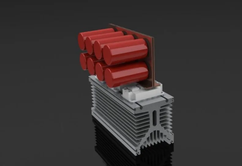
- Figure 16: DC-Bus IGBT heatsink and capacitance.
- Figure 17: IGBT module design on a fluid cooling system.
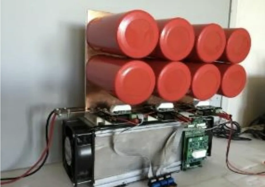
- Figure 18: Original 75 kW fan-assisted natural-air cooled three-phase inverter circuit.
- Figure 19: Original 75 kW liquid-cooled three-phase inverter circuit.
- Figure 20: Original three-phase 75 kW liquid cooled inverter circuit with six IGBT modules.
- Figure 21: Three-dimensional design visuals of the cooling module from the front, top and side.
- Figure 22: SKiM459GD12E4 IGBT module, adapter circuit, and IGBT driver assembly.
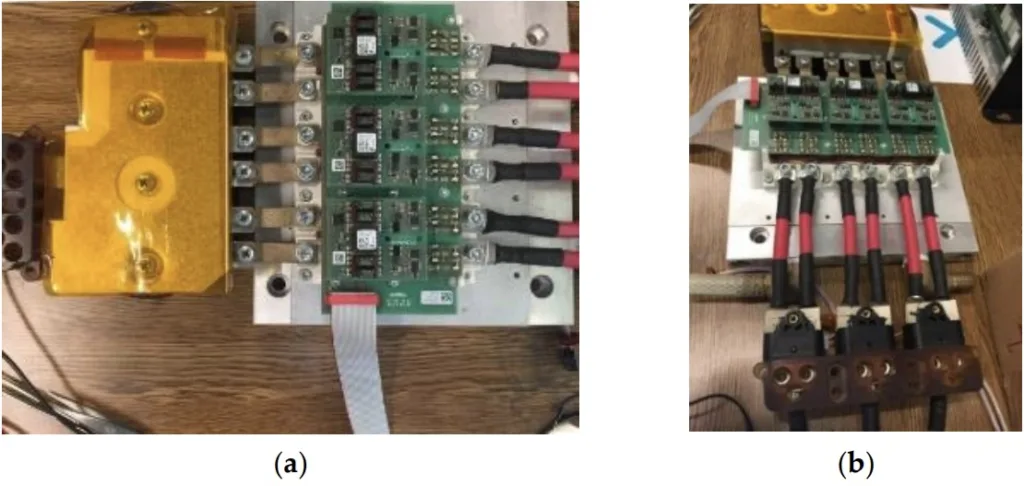
- Figure 23: (a) Original three-phase 75 kW liquid cooled inverter circuit with six IGBT modules; (b) Different angle view of Figure 23(a).
- Figure 24: The BLDC motor's rapid control prototyping block diagram with dSpace Micro-Auto Box.
- Figure 25: System engine-generator test platform with DS1401 dSpace Micro-Auto Box.
- Figure 26: BLDC motor phase currents and interphase voltages.
- Remember that this list is based on the extracted text and might not be entirely complete or perfectly accurate. Always refer to the original paper for definitive information.


6. 결론 및 논의:
세 가지 다른 전력 단계 설계와 세 가지 냉각 시스템을 비교 분석한 결과, 액냉 시스템이 가장 효율적인 것으로 나타났다. 본 연구는 전기 자동차의 효율 향상을 위한 전력 시스템 및 냉각 시스템 설계에 대한 중요한 시사점을 제공한다. 샌드위치 버스바 설계는 시스템 크기와 손실을 줄이는 데 효과적이다. IGBT 모듈의 배치 간격 최적화를 통해 열 저항을 줄일 수 있다.
연구의 한계점: 본 연구는 시뮬레이션과 실험실 환경에서 수행되었으며, 실제 주행 환경에서의 성능은 다를 수 있다.
7. 향후 후속 연구:
실제 주행 환경에서의 성능 검증, 다양한 주행 조건에 따른 냉각 시스템 성능 분석, 더욱 효율적인 냉각 시스템 설계 및 제어 알고리즘 개발 등의 후속 연구가 필요하다.
8. 참고문헌 요약:
논문에 인용된 모든 참고문헌 목록은 원본 그대로 추가되어야 한다. (본 요약에서는 생략)
저작권 및 참고 자료
본 자료는 Ali Bahadir, Omer Aydogdu, Elif Bahadir의 논문 "Three-Phase 75 kW Brushless Direct Current Motor for Electric Vehicles: Different Power Stage Design, Calculation of Losses, Cooling Techniques, and Comparison"을 기반으로 작성되었습니다.
https://doi.org/10.3390/app14041365
본 자료는 위 논문을 바탕으로 요약 작성되었으며, 상업적 목적으로 무단 사용이 금지됩니다.
Copyright © 2025 CASTMAN. All rights reserved.