본 소개 자료는 "[Journal/academic society of publication]"에 게재된 "[Inhomogeneous Skin Formation and Its Effect on the Tensile Behavior of a High Pressure Die Cast Recycled Secondary AlSi10MnMg(Fe) Alloy]" 논문을 기반으로 작성되었습니다.

1. 개요:
- 논문 제목: Inhomogeneous Skin Formation and Its Effect on the Tensile Behavior of a High Pressure Die Cast Recycled Secondary AlSi10MnMg(Fe) Alloy
- 저자: BISWAJIT DALAI, SIMON JONSSON, MANEL DA SILVA, LIANG YU, and JÖRGEN KAJBERG
- 발행 연도: 2024
- 게재 학술지/학회: Metallurgical and Materials Transactions A
- 키워드: 논문에 명시되지 않음
2. 초록:
본 연구는 고압 다이캐스팅(HPDC)으로 제조된 새로운 2차 합금의 미세조직 변화, 기계적 특성 및 파괴 거동을 조사했습니다. 주조 상태의 미세조직은 (i) 초정 α-Al, (ii) α-Al15(FeMn)3Si2 금속간 화합물, (iii) Al-Si 공정으로 구성되었습니다. HPDC 주조품의 표면에서 깊이 방향으로의 미세조직은 (i) 표면의 미세립 스킨층, (ii) 중간 영역의 증가된 Al-Si 공정, (iii) 중심부의 조대한 α-Al 수지상정으로 이루어졌습니다. 이에 따라 경도는 스킨층에서 중간 영역으로 갈수록 증가하다가 주조품 중심부로 가면서 감소했습니다. 스킨층의 형성은 매우 불연속적이었으며, 이는 다이 캐비티 내부의 복잡한 유동 패턴에 기인합니다. 스킨층은 HPDC 합금의 강도를 약간 향상시키는 것으로 나타났으나, 재료의 연성을 큰 편차와 함께 제한했습니다. 이러한 연성 거동은 불균일한 스킨층이 인접 기지와의 불량한 결합력 때문에 유발하는 파괴 메커니즘에서 비롯되었습니다. 비록 2차 합금이 파괴의 주요 원인으로 알려진 주조 결함과 α-Al15(FeMn)3Si2 금속간 화합물을 포함하고 있음에도 불구하고, 본 연구에서는 불균일한 스킨층의 영향이 지배적인 것으로 나타났습니다.
3. 서론:
고압 다이캐스팅(HPDC)은 높은 생산성을 가진 공정으로, 자동차 산업에서 섀시 및 차체(BIW) 구조물과 같이 기하학적으로 정밀하고 얇은 벽 두께를 가진 부품을 생산하는 데 널리 사용됩니다. 전통적인 HPDC 합금은 종종 Al-Si-Mg계를 기반으로 합니다. 이러한 합금은 일반적으로 불순물로 Fe(0.8-1.1 wt pct)를 함유하는데, 이는 다이 점착(die sticking)을 방지하는 데 도움이 되지만 해로운 침상(needle-shaped) β-Al5FeSi 화합물을 형성하여 기계적 특성, 특히 연성을 저하시킵니다. 이를 완화하기 위해 Fe 함량을 제한(<0.25 wt pct)하고 Mn을 첨가(0.4-0.8 wt pct)한 1차 AlSi10MnMg 합금(예: EN AC-43500)이 개발되었습니다. Mn은 "철 보정제(iron corrector)" 역할을 하여 β-Fe 대신 덜 해로운 α-Fe 금속간 화합물 형성을 촉진하고, 감소된 Fe 함량으로 인한 다이 점착 경향을 보완합니다. 그러나 낮은 Fe 수준을 달성하면 희석 필요성 때문에 생산 비용이 증가합니다. 지속 가능성 및 비용 절감에 대한 관심이 높아짐에 따라, 스크랩 재활용으로 인해 본질적으로 더 높은 Fe 함량을 갖는 2차(재활용) Al-Si 합금 사용에 대한 관심이 증가하고 있습니다. 본 연구는 HPDC 공정으로 제조된 재활용 2차 AlSi10MnMg(Fe) 합금의 미세조직, 기계적 거동 및 파괴 메커니즘을 이해하는 데 초점을 맞추며, 특히 종종 간과되는 표면 스킨층 형성과 그 잠재적 불균일성에 특별한 주의를 기울입니다.
4. 연구 요약:
연구 주제 배경:
자동차 산업은 경량 Al-Si 합금 부품 생산을 위해 HPDC를 활용합니다. Fe 함량 관리가 중요합니다. 높은 Fe는 해로운 β-Fe 상을 형성하고, 낮은 Fe는 비용과 다이 점착 가능성을 증가시킵니다. 1차 합금은 낮은 Fe와 Mn 첨가(α-Fe 형성)를 사용하여 특성과 주조성의 균형을 맞춥니다. 2차(재활용) 합금은 비용 및 환경적 이점을 제공하지만 Fe 함량이 높아 β-Fe를 피하기 위해 신중한 제어(예: Mn:Fe 비율)가 필요합니다. 금속간 화합물, 결함, 표면 스킨과 같은 미세조직 특징은 HPDC 부품의 최종 특성에 큰 영향을 미칩니다.
선행 연구 현황:
1차 AlSi10MnMg HPDC 합금에 대한 연구는 일반적인 미세조직(α-Al, α-Fe, Al-Si 공정), 표면(미세)에서 중심(조대)까지의 변화, 다양한 α-Fe 형태를 특성화했습니다. 파괴는 종종 큰 기공, 표면 결함 또는 응력 집중원으로 작용하는 α-Fe 입자와 관련됩니다. 2차 AlSi10MnMg(Fe) 합금 연구는 β-Fe 형성을 억제하기 위해 Mn:Fe 비율(일반적으로 0.58-1.3)을 최적화하는 데 중점을 두었습니다. 이들의 미세조직은 1차 합금과 유사하며, 파괴 역시 큰 α-Fe 화합물이나 라미네이션과 같은 주조 결함에서 시작되는 것으로 보고되었습니다. 그러나 불균일한 표면 스킨의 형성과 영향은 파단면에서 때때로 암시적으로 관찰되었음에도 불구하고 체계적으로 조사되지 않아 지식 격차를 나타냅니다.
연구 목적:
본 연구는 진공 보조 HPDC 공정으로 생산된 새로운 재활용 2차 AlSi10MnMg(Fe) 합금의 미세조직 변화, 기계적 특성 및 파괴 거동을 조사하는 것을 목표로 했습니다. 표면 스킨 형성, 그 잠재적 불균일성, 그리고 합금의 인장 응답, 특히 최근 구조 응용 분야와 관련된 얇은 벽(2mm) 주조품에 대한 영향에 특별한 초점을 맞췄습니다.
핵심 연구 내용:
본 연구의 핵심은 다음을 포함합니다:
- OM, SEM, EDS를 사용하여 2차 AlSi10MnMg(Fe) 합금의 주조 상태 미세조직 특성화. 상 식별(α-Al, α-Fe, 공정), 형태 및 2mm 두께에 걸친 분포에 중점.
- 표면 스킨층의 형성과 균일성을 다른 위치에서 조사.
- HPDC 부품에 존재하는 주조 결함 식별.
- 주조 두께에 따른 경도 분포 측정.
- 원래 스킨이 있는 시편과 스킨을 제거한 시편에 대한 단축 인장 시험을 수행하여 스킨이 강도와 연성에 미치는 영향 평가.
- 고속 카메라 이미징, SEM 파단면 분석, 측면 OM 분석을 이용한 상세 파괴 분석. 균열 개시 및 전파 메커니즘을 관찰된 미세조직 및 스킨 불균일성과 구체적으로 연결하여 이해.
5. 연구 방법론
연구 설계:
본 연구는 실험적 접근 방식을 사용했습니다. 재활용 2차 AlSi10MnMg(Fe) 합금을 진공 보조 HPDC 공정을 사용하여 계단형 부품으로 주조했습니다. 2mm 두께 섹션에서 채취한 샘플을 미세조직 특성화, 경도 시험, 단축 인장 시험(표면 스킨 유무 비교)에 사용했습니다. 파단면과 인접 측면을 분석하여 기계적 거동을 미세조직 특징, 특히 스킨 불균일성과 연관시켰습니다.
데이터 수집 및 분석 방법:
- 재료: Raffmetal에서 공급한 2차 AlSi10MnMg(Fe) 합금 (조성은 Table I 참조, 특히 Si: 9.547, Fe: 0.297, Mn: 0.65, Mg: 0.218 wt pct, Mn:Fe ≈ 2.1).
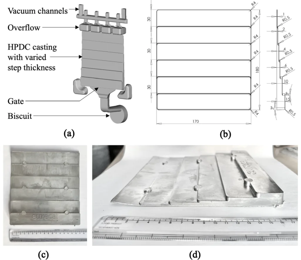
- HPDC 공정: Buhler 콜드 챔버 기계(5250 kN 형체력)를 사용하여 계단형 부품 주조(Fig 1b). 주요 매개변수: 용탕 온도 700-720 °C, 플런저 속도 4 m/s (충전 단계), 계산된 탕구 속도 42 m/s, VDS 진공 시스템(85-100 mbar), 최종 압력 900-950 bar.
- 미세조직 특성화: 2mm 스텝에서 샘플을 절단, 마운팅, 연마(P120 ~ P4000 SiC 페이퍼), 폴리싱(1-µm 다이아몬드, 0.05-µm OPS). 광학 현미경(OM)은 Nikon Eclipse MA200 사용. 주사 전자 현미경(SEM) 및 에너지 분산형 X선 분광법(EDS)은 FEI Magellan 400 XHR SEM을 사용하여 상 조성 분석 수행.
- 기계적 시험:
- 경도: 비커스 미세 경도(Struers Duramin-40, 0.05 kgf 하중, 10초 유지 시간)를 폴리싱된 단면에서 측정.
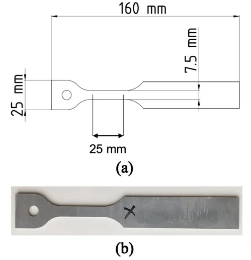
- 인장 시험: 2mm 스텝 중앙에서 가공된 평판 시편(Fig 3a). 두 세트 시험: '스킨 있음'(표면 P1200 페이퍼로 연마) 및 '스킨 없음'(각 표면에서 ~150 µm를 P1200까지 연마하여 제거 후, 게이지부 P1200 연마). Instron 1272 기계에서 2 mm/min(변형률 속도 0.001 s⁻¹)으로 시험, 신율계(게이지 길이 25 mm) 사용. Phantom V2512 고속 카메라(96,000 frames/s)로 균열 개시 기록.
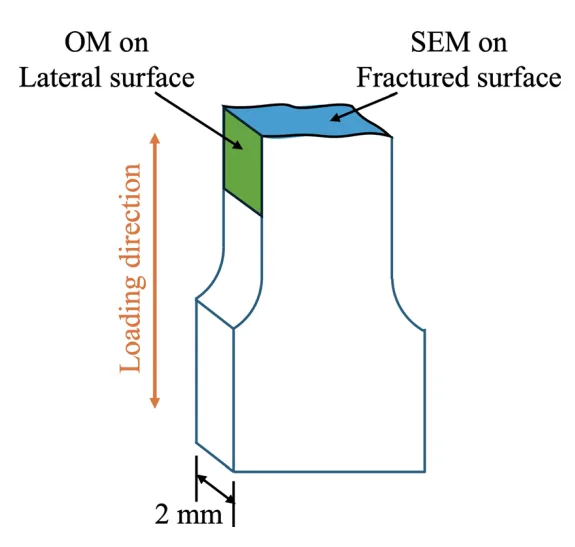
- 파괴 분석: SEM(Magellan, 3 kV, 0.8 nA, ETD 검출기)을 파단면 분석에 사용. OM(Nikon)을 파단면 인접 폴리싱된 측면 분석에 사용(Fig 4).
- 응고 시간/냉각 속도 추정: OM 이미지에서 2차 덴드라이트 암 간격(SDAS, d) 측정(Fig 9). Han과 Zhang [41]의 경험식(Eq. [1]-[3])을 사용하여 측정된 SDAS와 근사된 TL(600 °C), TS(590 °C)를 이용하여 국부 응고 시간(ts) 및 냉각 속도(q) 추정.
연구 주제 및 범위:
본 연구는 HPDC 공정으로 2mm 두께 주조품으로 제조된 특정 재활용 2차 AlSi10MnMg(Fe) 합금에 초점을 맞췄습니다. 범위는 다음을 포함합니다:
- 주조 상태 미세조직의 상세 분석: 상 구성 요소, 형태, 두께 방향 분포.
- 표면 스킨 형성, 특성, 특히 불균일성 조사.
- 일반적인 주조 결함 식별.
- 미세조직과 경도 분포의 상관관계.
- 표면 스킨이 인장 특성(YS, UTS, 연신율)에 미치는 영향 평가.
- 불균일 스킨의 역할 대 결함 및 금속간 화합물과 같은 다른 요인의 역할을 강조하며 파괴 메커니즘 규명.
6. 주요 결과:
주요 결과:
- 미세조직: 주조 상태 미세조직은 초정 α-Al (수지상정 (α-Al)I 및 구상 (α-Al)II), α-Al15(FeMn)3Si2 금속간 화합물 (다각형 (α-Fe)I, 미세 다각형 (α-Fe)II, 차이니즈 스크립트), Al-Si 공정으로 구성됨 (Fig 5). Mn:Fe 비율 ~2.1은 해로운 β-Al5FeSi 형성을 성공적으로 억제함. EDS 분석으로 α-Fe 상의 조성 확인 (Table II).
- 미세조직 구배: 2mm 두께에 걸쳐 뚜렷한 미세조직 구배 존재: 미세립 α-Al 스킨 (Region 1, ~30-150 µm 두께), 증가된 Al-Si 공정을 갖는 중간 영역 (Region 2), 조대한 α-Al 수지상정 ((α-Al)I)이 지배적인 중심부 (Region 3) (Fig 6).
- 불균일 스킨: 스킨 형성은 매우 불균일한 것으로 밝혀짐. 스킨층의 갑작스러운 소멸, 스킨이 표면에서 내부로 이동하는 모습, 일부 표면에서 스킨이 완전히 없는 경우 관찰됨 (Fig 7).
- 주조 결함: 콜드 플레이크, 콜드 샷, 수축 기공, 불균일 스킨과 관련된 라미네이션 등 다양한 결함 식별됨 (Fig 8).
- SDAS 및 냉각 속도: 평균 SDAS는 스킨(Region 1)의 3.6 µm에서 중심(Region 3)의 14.6 µm로 증가함 (Fig 9). 추정된 냉각 속도는 스킨에서 ~33 °C/s, 중심에서 ~0.5 °C/s였으나, 이는 대략적인 추정치임 (Table III).
- 경도 분포: 경도는 스킨(~86 HV)에서 중간 영역(더 많은 공정 때문)으로 증가한 후 중심(조대한 α-Al 때문)으로 감소함 (Fig 10). 압흔 아래 상 혼합과 관련하여 경도의 상당한 국부적 변화 관찰됨.
- 인장 특성: 스킨이 있는 시편은 스킨이 없는 시편에 비해 평균 YS는 약간 높았으나(117.6 MPa vs 111.3 MPa), 평균 UTS(221.8 MPa vs 237 MPa) 및 평균 총 연신율(TE)(4.2% vs 6.2%)은 상당히 낮았음 (Fig 11, 12). 결정적으로, 스킨이 있는 시편은 UTS와 TE 모두에서 훨씬 큰 편차(분산)를 보임.
- 파괴 거동: 고속 카메라 이미징 결과, 스킨이 있는 시편은 시편 가장자리에서 균열이 시작되었으나, 스킨이 없는 시편은 평평한 표면에서 시작됨 (Fig 13). SEM 파단면 분석 결과, 불균일 스킨 존재에 해당하는 모서리/가장자리에서 취성 파괴 개시 특징이 나타남 (Fig 14). 측면 OM 분석 결과, 낮은 연신율에서 파단된 시편 B와 C의 균열 개시 부위 인근에서 불규칙하거나 내부로 이동한 스킨층이 확인됨 (Fig 15, 16). 불균일 스킨과 하부 기지 사이의 약한 결합 계면을 따른 박리가 이러한 경우 주요 파괴 개시 메커니즘으로 식별됨 (Fig 14c, 15c3, 16b). 균열 전파는 주로 Al-Si 공정 영역을 통해 일어나며, Si 입자와 α-Fe 금속간 화합물을 파단시킴 (Fig 18).
- 지배적 요인: 본 연구는 불균일한 스킨 형성이 약한 결합과 박리를 유발하여, 시험된 HPDC 2차 합금 시편(스킨 있음)의 파괴 거동을 제어하고 연성(큰 편차 유발)을 제한하는 주요 요인이며, 해당 특정 경우 주조 결함 및 α-Fe 입자의 영향을 능가한다고 결론지음. 스킨층 제거는 개선되고 더 일관된 연성을 가져옴.
그림 이름 목록:
- Fig. 1—(a) Diagram of HPDC configuration showing different parts, (b) Schematic diagram showing the dimensions of the die used in the HPDC process, (c) Top view of an actual cast part, and (d) Side view of an actual cast part showing the steps with different wall thicknesses.
- Fig. 2—Graphical representation of an as-cast part of 2-mm wall thickness, with green and red colored boxes, respectively, indicating the locations used for microscopic analysis and hardness measurements. The pink arrows indicate the two casting surfaces on which the skin layer is supposedly formed (Color figure online).
- Fig. 3—(a) Schematic diagram showing the dimensions of specimen used for uniaxial tensile tests, and (b) An actual tensile specimen machined from the as-cast part with 2-mm wall thickness.
- Fig. 4—Graphical representation of a tensile tested specimen indicating the fractured and lateral surface on which SEM and OM analyses were performed, respectively.
- Fig. 5—OM image showing different features formed in the as-cast AlSi10MnMg(Fe) alloy with 2-mm wall thickness.
- Fig. 6—OM image showing the microstructure evolution through the thickness of a 2-mm-thick as-cast part of AlSi10MnMg(Fe) alloy.
- Fig. 7—OM images showing inhomogeneous formation of skin layer in 2-mm-thick as-cast step of AlSi10MnMg(Fe) alloy: (a) Sudden disappearance of surface skin, indicated by red arrow marks, (b) Formation of skin layer moving through the depth away from the surface, indicated by purple arrow marks, and (c) Absence of skin layer on one of the casting surfaces (Color figure online).
- Fig. 8—OM images showing different casting defects produced in 2-mm-thick as-cast step part of AlSi10MnMg(Fe) alloy: (a) Cold flake with conspicuous flat edge indicated by red arrow marks, (b) Cold shot, (c) Shrinkage pore, and (d) Lamination due to inhomogeneous skin formation, indicated by purple arrow marks (Color figure online).
- Fig. 9—OM images on a 2-mm-thick as-cast step part of AlSi10MnMg(Fe) alloy showing the SDAS measurements taken in (a) Region 1: skin, and (b) Region 3: center.
- Fig. 10—(a) OM image on the indentations created during the microhardness test on 2-mm-thick as-cast step part of AlSi10MnMg(Fe) alloy, indicating their relative positions with respect to different microstructural regions, and (b) the corresponding hardness distribution through the depth. The red and purple arrow marks in (b) indicate the relatively large variation in the corresponding hardness values (Color figure online).
- Fig. 11—Engineering stress vs engineering strain curves obtained from the tensile tests of six AlSi10MnMg(Fe) alloy specimens having 2-mm wall thickness: Samples A, B, and C tested in the as-cast state by retaining skin; Samples D, E, and F tested after removing the skin.
- Fig. 12—Mean yield strength (YS) at 0.2 pct offset, mean ultimate tensile strength (UTS), and mean total elongation (TE), obtained from the tensile tests of secondary alloy specimens with and without skin. Error bars here indicate the standard deviations calculated in each case.
- Fig. 13—Images captured by the high-speed camera during the tensile tests of samples: (a) A, (b) B, (c) C, (d) D, (e) E, and (f) F. (a through c) and (d through f), respectively, display the tensile samples with and without skin. The yellow arrow in the images shown in the top row indicates the crack initiation in each case, with the images in the bottom row manifesting the crack propagation at a later time step (Color figure online).
- Fig. 14—SEM images of crack initiation site, marked by red dashed rectangle, in tensile tested samples: (a) A, (b) B, (c) C, and (e) F. The blue arrows in (c) indicate a fringe of delamination. (d) is the zoomed-in image of the area enclosed by yellow rectangle in (c), with the green dashed box indicating the presence of very fine grains (Color figure online).
- Fig. 15—OM images showing the lateral surface of the fractured samples with skin: (a) A, (b) B, and (c) C, with the red arrows in (a through c) indicating the crack initiation site corresponding to Figs. 14(a through c). (a1 through a3) are the magnified images of the areas enclosed by yellow box in (a). (b1, b2) are the magnified images of the areas enclosed by blue box in (b). (c1 through c3) are the magnified images of the areas enclosed by pink box in (c) (Color figure online).
- Fig. 16—OM images on the lateral surface of other fractured part of sample C with skin (complementary of the one already shown in Fig. 15(c)): (a) Depiction of surface skin and a cold flake, and (b) Magnified image of the crack initiation site marked by yellow rectangle in (a), with red and white dashed lines indicating the inhomogeneous skin and initial casting surface, respectively (Color figure online).
- Fig. 17—(a) OM image showing the lateral surface of the fractured sample F without skin. (a1) and (a2) are, respectively the magnified images of the areas enclosed by yellow and blue boxes in (a) (Color figure online).
- Fig. 18—SEM images on the fractured surfaces of tensile tested samples displaying (a) matrix of the fractured surface with yellow and blue arrows indicating primary α-Al and Al-Si eutectics, respectively, (b) Al-Si eutectics, (c) fractured Si particle within Al solid solution, (d) cracked Chinese script α-Fe compound, (e) cracked (α-Fe)II compound along with an uncracked (α-Fe)II compound, (f) uncracked (α-Fe)I compound, and (g) shrinkage pore with white arrows indicating α-Al dendritic arms. The red arrows in (b through e) indicate cracks (Color figure online).
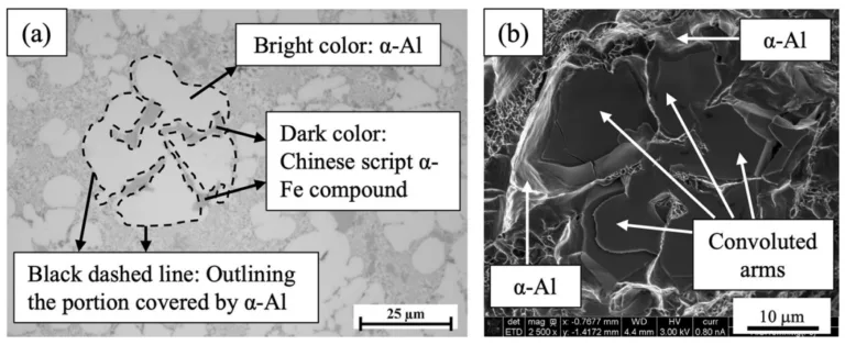
- Fig. 19—Appearance of Chinese script α-Fe compound in: (a) OM image of an as-cast part, and (b) SEM image of a tensile tested part.
- Fig. 20—Still images from simulation of die filling pattern with increasing time from left to right.
- Fig. 21—Yield strength at 0.2 pct offset and total elongation exhibited by the HPDC recycled secondary alloy used in the current study along with the range of properties for the primary trimal®-05 alloy obtained from the datasheet of Trimet[37] (the artwork presented here is original and only the data from the cited source is used).
7. 결론:
HPDC 공정으로 제조된 재활용 2차 AlSi10MnMg(Fe) 합금(2mm 벽 두께) 조사 결과, 다음과 같은 결론을 도출했습니다:
- 합금 조성(Mn:Fe ≈ 2.1)은 해로운 β-Fe 형성을 효과적으로 억제하고, 덜 해로운 다각형 및 차이니즈 스크립트 α-Fe 화합물 형성을 선호했습니다. 차이니즈 스크립트 구조는 3D에서 복잡하게 얽힌 팔(arm) 형태로 나타납니다.
- 미세조직은 두께 방향으로 구배를 보입니다: 미세립 스킨, 증가된 Al-Si 공정, 중심부의 조대한 α-Al 수지상정 순서입니다. 평균 SDAS는 스킨의 3.6 µm에서 중심의 14.6 µm로 증가했으며, 이는 각각 ~10 °C/s 및 ~1 °C/s의 추정 냉각 속도에 해당합니다. 경도는 이 구배를 따라 스킨에서 중간층으로 증가했다가 중심으로 감소합니다.
- 스킨층 형성은 연속적이거나 균일하지 않으며, 이는 다이 캐비티 내의 복잡한 유동 및 다양한 열 전달에 기인합니다. "파도와 호수(waves and lakes)" 결함과 유사한 불균일 스킨 구조가 관찰되었습니다.
- 스킨층은 항복 강도를 향상시키는 일부 징후를 보이지만, 그 불연속성과 제한된 두께로 인해 효과가 제한적일 수 있습니다. 그러나 불균일 스킨은 연성을 현저히 제한하고 급격한 파단을 유발합니다.
- 불균일 스킨은 인접 기지와의 약한 결합으로 인해 박리 유도 균열을 촉진합니다. 이 메커니즘은 급격한 파단으로 이어질 수 있으며, 스킨이 있는 연구된 시편에서는 주조 결함이나 α-Fe 화합물과 같은 다른 요인보다 인장 연성에 더 해로운 것으로 보입니다.
- 재활용 2차 합금은 상용 1차 합금과 유사한 수준의 강도 및 연성을 달성할 잠재력이 있으며, 특히 불균일 스킨 형성의 해로운 영향을 완화할 수 있다면(예: 표면 제거 또는 공정 최적화) 더욱 그렇습니다.
8. 참고 문헌:
- [1] J.G. Kaufman and E.L. Rooy: Aluminum Alloy Castings: Properties, Processes and Applications, ASM International, Detroit, 2004, pp. 7-20.
- [2] T.O. Mbuya, B.O. Odera, and S.P. Ng’ang’a: Int. J. Cast Met. Res., 2003, vol. 16, pp. 451-65. https://doi.org/10.1080/13640461.2003.11819622.
- [3] L. Wang, M. Makhlouf, and D. Apelian: Int. Mater. Rev., 1995, vol. 40, pp. 221-38. https://doi.org/10.1179/imr.1995.40.6.221.
- [4] L. Zhang, J. Gao, L.N.W. Damoah, and D.G. Robertson: Miner. Process. Extr. Metall. Rev., 2012, vol. 33, pp. 99–157. https://doi.org/10.1080/08827508.2010.542211.
- [5] G. Gustafsson, T. Thorvaldsson, and G.L. Dunlop: Metall. Trans. A, 1986, vol. 17, pp. 45-52. https://doi.org/10.1007/BF02644441.
- [6] P. Crepeau: Trans. Am. Foundryman’s Soc., 1995, vol. 103, pp. 361-66.
- [7] D. Apelian: Aluminum Cast Alloys: Enabling Tools for Improved Performance, North American Die Casting Association, Wheeling, 2009, pp. 5-18.
- [8] J.A. Taylor: Procedia Mater. Sci., 2012, vol. 1, pp. 19-33. https://doi.org/10.1016/j.mspro.2012.06.004.
- [9] S.A.V.S. p. A. Società Alluminio Veneto: Aluminium Alloys Ingots for Remelting: Alloy Data Sheet, S.A.V.S. p. A. Società Alluminio Veneto, 2020. https://www.sav-al.com/file?oid=613fle4c10834b044515e1f3. Accessed 26 July 2024.
- [10] Rheinhfelden Alloys: Primary Aluminium Alloys for Pressure Die Casting, Rheinhfelden Alloys, 2015. https://rheinfelden-alloys.eu/wp-content/uploads/2016/01/05-HB-DG_Ci_Sf_Cm_Td_Ma_RHEINFELDEN-ALLOYS_2015_EN.pdf. Accessed 26 July 2024.
- [11] L.A. Narayanan, F.H. Samuel, and J.E. Gruzleski: Metall. Mater. Trans. A, 1994, vol. 25A, pp. 1761-73. https://doi.org/10.1007/BF02668540.
- [12] M. da Silva, J. Pujante, J. Hrabia-Wiśnios, B. Augustyn, D. Kapinos, M. Węgrzyn, and S. Boczkal: Metals, 2024, vol. 14, p. 626. https://doi.org/10.3390/met14060626.
- [13] E. Cinkilic, M. Moodispaw, J. Zhang, J. Miao, and A.A. Luo: Metall. Mater. Trans. A, 2022, vol. 53A, pp. 2861-73. https://doi.org/10.1007/s11661-022-06711-4.
- [14] D. Bösch, S. Pogatscher, M. Hummel, W. Fragner, P.J. Uggowitzer, M. Göken, and H.W. Höppel: Metall. Mater. Trans. A, 2015, vol. 46A, pp. 1035–45. https://doi.org/10.1007/s11661-014-2700-8.
- [15] R. Lumley: JOM, 2019, vol. 71, pp. 382-90. https://doi.org/10.1007/s11837-018-3121-8.
- [16] F. Liu, H. Zhao, R. Yang, and F. Sun: Materials, 2019, vol. 12, p. 2065. https://doi.org/10.3390/ma12132065.
- [17] X.Y. Jiao, Y.X. Liu, J. Wang, W.N. Liu, A.X. Wan, S. Wiesner, and S.M. Xiong: J. Mater. Sci. Technol., 2023, vol. 140, pp. 201-09. https://doi.org/10.1016/j.jmst.2022.09.014.
- [18] R. Liu, J. Zheng, L. Godlewski, J. Zindel, M. Li, W. Li, and S. Huang: Mater. Sci. Eng. A, 2020, vol. 783, p. 139280. https://doi.org/10.1016/j.msea.2020.139280.
- [19] X.Y. Jiao, Y.F. Zhang, J. Wang, H. Nishat, Y.X. Liu, W.N. Liu, H.X. Chen, and S.M. Xiong: J. Mater. Process. Technol., 2021, vol. 298, p. 117299. https://doi.org/10.1016/j.jmatprotec.2021.117299.
- [20] X.Y. Jiao, C.F. Liu, Z.P. Guo, G.D. Tong, S.L. Ma, Y. Bi, Y.F. Zhang, and S.M. Xiong: J. Mater. Sci. Technol., 2020, vol. 51, pp. 54-62. https://doi.org/10.1016/j.jmst.2020.02.040.
- [21] G. Ubertalli, F. D’Aiuto, S. Plano, and D. De Caro: Procedia Struct. Integr., 2016, vol. 2, pp. 3617-24. https://doi.org/10.1016/j.prostr.2016.06.451.
- [22] E. Fracchia, F.S. Gobber, and M. Rosso: Metals, 2020, vol. 10, p. 618. https://doi.org/10.3390/met10050618.
- [23] X.Y. Jiao, P.Y. Wang, Y.X. Liu, J. Wang, W.N. Liu, A.X. Wan, L.J. Shi, C.G. Wang, and S.M. Xiong: J. Mater. Res. Technol., 2023, vol. 25, pp. 1129-40. https://doi.org/10.1016/j.jmrt.2023.05.281.
- [24] A. Niklas, A. Baquedano, S. Orden, E. Noguès, M. Da Silva, and A.I. Fernández-Calvo: Key Eng. Mater., 2016, vol. 710, pp. 244-49. https://doi.org/10.4028/www.scientific.net/KEM.710.244.
- [25] J.M. Sanchez, M. Arribas, H. Galarraga, M. Garcia de Cortazar, M. Ellero, and F. Girot: Heliyon, 2023, vol. 9, p. e13005. https://doi.org/10.1016/j.heliyon.2023.e13005.
- [26] E. Cinkilic, C.D. Ridgeway, X. Yan, and A.A. Luo: Metall. Mater. Trans. A, 2019, vol. 50A, pp. 5945-56. https://doi.org/10.1007/s11661-019-05469-6.
- [27] J. Piątkowski, M. Hejne, and R. Wieszała: Arch. Mater. Sci. Eng., 2023, vol. 123, pp. 5-12. https://doi.org/10.5604/01.3001.0053.9750.
- [28] L.B. Otani, J. Soyama, G. Zepon, A. Costa e Silva, C.S. Kiminami, W.J. Botta, and C. Bolfarini: J. Phase Equilib. Diffus., 2017, vol. 38, pp. 298-304. https://doi.org/10.1007/s11669-017-0542-y.
- [29] A. Bakedano, R. González-Martínez, A. Niklas, M. Da Silva, M. Garat, and A.I. Fernández-Calvo: 71st World Foundry Congress on Advanced Sustainable Foundry, 2014.
- [30] A. Niklas, A.I. Fernández-Calvo, A. Bakedano, S. Orden, M. Da Silva, E. Nogués, and E. Roset: Metall. Ital., 2016, vol. 108, pp. 9-12.
- [31] A. Niklas, A. Bakedano, S. Orden, M. da Silva, E. Nogués, and A.I. Fernández-Calvo: Mater. Today Proc., 2015, vol. 2, pp. 4931-38. https://doi.org/10.1016/j.matpr.2015.10.059.
- [32] H. Zheng, Y. Jiang, F. Liu, and H. Zhao: J. Alloys Compd., 2024, vol. 976, p. 173167. https://doi.org/10.1016/j.jallcom.2023.173167.
- [33] Z. Yuan, Z. Guo, and S.M. Xiong: J. Mater. Sci. Technol., 2019, vol. 35, pp. 1906–16. https://doi.org/10.1016/j.jmst.2019.05.011.
- [34] H.M. Yang, Z. Guo, and S.M. Xiong: J. Mater. Process. Technol., 2020, vol. 275, p. 116377. https://doi.org/10.1016/j.jmatprotec.2019.116377.
- [35] S. Otarawanna, C.M. Gourlay, H.I. Laukli, and A.K. Dahle: Mater. Chem. Phys., 2011, vol. 130, pp. 251-58. https://doi.org/10.1016/j.matchemphys.2011.06.035.
- [36] Y. Yang, S. Huang, J. Zheng, L. Yang, X. Cheng, R. Chen, and H. Wei-Jian: Trans. Nonferr. Met. Soc. China, 2024, vol. 34, pp. 378-91. https://doi.org/10.1016/S1003-6326(23)66405-2.
- [37] Trimet-05: Trimal®-05-Die Cast Alloy for Crash-Relevant Applications, Trimet-05, 2008. https://www.trimet.eu/en/products/foundry-alloys/trimal-05. Accessed 26 July 2024.
- [38] C.M. Dinnis, J.A. Taylor, and A.K. Dahle: Scripta Mater., 2005, vol. 53, pp. 955-58. https://doi.org/10.1016/j.scriptamat.2005.06.028.
- [39] J.I. Goldstein, D.E. Newbury, J.R. Michael, N.W.M. Ritchie, J.H.J. Scott, and D.C. Joy: Scanning Electron Microscopy and X-Ray Microanalysis, 4th ed. Springer, New York, 2018. https://doi.org/10.1007/978-1-4939-6676-9.
- [40] B. Dybowski, A. Kiełbus, and Ł Poloczek: Eng. Fail. Anal., 2023, vol. 150, p. 107223. https://doi.org/10.1016/j.engfailanal.2023.107223.
- [41] Q. Han and J. Zhang: Metall. Mater. Trans. B, 2020, vol. 51B, pp. 1795-1804. https://doi.org/10.1007/s11663-020-01858-0.
- [42] H. Yang, S. Ji, and Z. Fan: Mater. Des., 2015, vol. 85, pp. 823-32. https://doi.org/10.1016/j.matdes.2015.07.074.
- [43] X. Dong, X. Zhu, and S. Ji: J. Mater. Process. Technol., 2019, vol. 266, pp. 105-13. https://doi.org/10.1016/j.jmatprotec.2018.10.030.
- [44] X.Y. Jiao, C.F. Liu, Z.P. Guo, H. Nishat, G.D. Tong, S.L. Ma, Y. Bi, Y.F. Zhang, S. Wiesner, and S.M. Xiong: J. Alloys Compd., 2021, vol. 862, p. 158580. https://doi.org/10.1016/j.jallcom.2020.158580.
- [45] S. Otarawanna, C.M. Gourlay, H.I. Laukli, and A.K. Dahle: Metall. Mater. Trans. A, 2009, vol. 40A, pp. 1645-59. https://doi.org/10.1007/s11661-009-9841-1.
- [46] S. Ji, Y. Wang, D. Watson, and Z. Fan: Metall. Mater. Trans. A, 2013, vol. 44A, pp. 3185-97. https://doi.org/10.1007/s11661-013-1663-5.
- [47] S. Ji, W. Yang, F. Gao, D. Watson, and Z. Fan: Mater. Sci. Eng. A, 2013, vol. 564, pp. 130-39. https://doi.org/10.1016/j.msea.2012.11.095.
- [48] H. Becker, T. Bergh, P.E. Vullum, A. Leineweber, and Y. Li: Materialia, 2019, vol. 5, p. 100198. https://doi.org/10.1016/j.mtla.2018.100198.
- [49] Α.Κ.Μ.Α. Ahamed and H. Kato: Mater. Trans., 2008, vol. 49, pp. 1621-28. https://doi.org/10.2320/matertrans.F-MRA2008814.
- [50] H. Kato, T. Suzuki, Y. Annou, and K. Kageyama: Mater. Trans., 2004, vol. 45, pp. 2403-09. https://doi.org/10.2320/matertrans.45.2403.
- [51] Z.W. Chen: Mater. Sci. Eng. A, 2003, vol. 348, pp. 145-53. https://doi.org/10.1016/S0921-5093(02)00747-5.
- [52] S. Midson: Die Casting Defects, North American Die Casting Association. https://pdfcoffee.com/nadca-overview-of-defets-in-die-casting-pdf-free.html. Accessed 4 Sep 2024.
9. 저작권:
- 본 자료는 "BISWAJIT DALAI, SIMON JONSSON, MANEL DA SILVA, LIANG YU, and JÖRGEN KAJBERG"의 논문입니다. "Inhomogeneous Skin Formation and Its Effect on the Tensile Behavior of a High Pressure Die Cast Recycled Secondary AlSi10MnMg(Fe) Alloy"를 기반으로 합니다.
- 논문 출처: https://doi.org/10.1007/s11661-024-07631-1
본 자료는 상기 논문을 바탕으로 요약되었으며, 상업적 목적의 무단 사용을 금합니다.
Copyright © 2025 CASTMAN. All rights reserved.


