적층 제조(AM)를 위한 HPDC 다이 설계: 경량화와 열 응력의 한계를 넘어서
이 기술 요약은 Mohammadali Baradaran과 Ambareeksh Tharayil Pradeep이 2018년 12월 Jönköping University에 제출한 학술 논문 "HPDC Die design for Additive Manufacturing: Simulation and Comparison of Thermal Stresses in HPDC die designed for Additive Manufacture"를 기반으로 합니다.
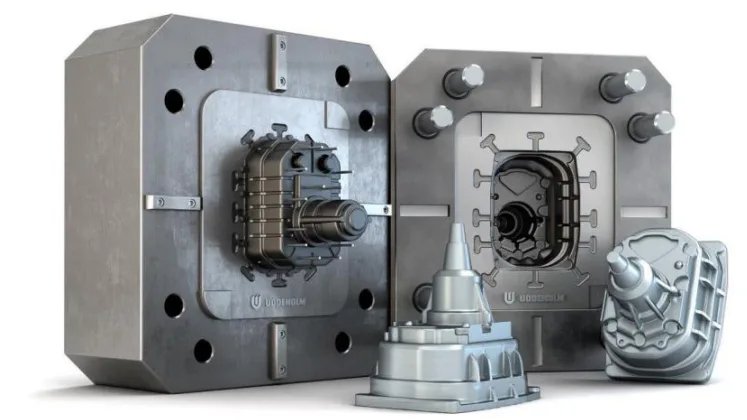
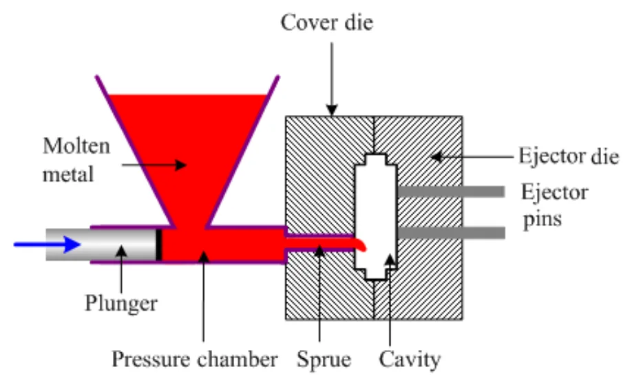
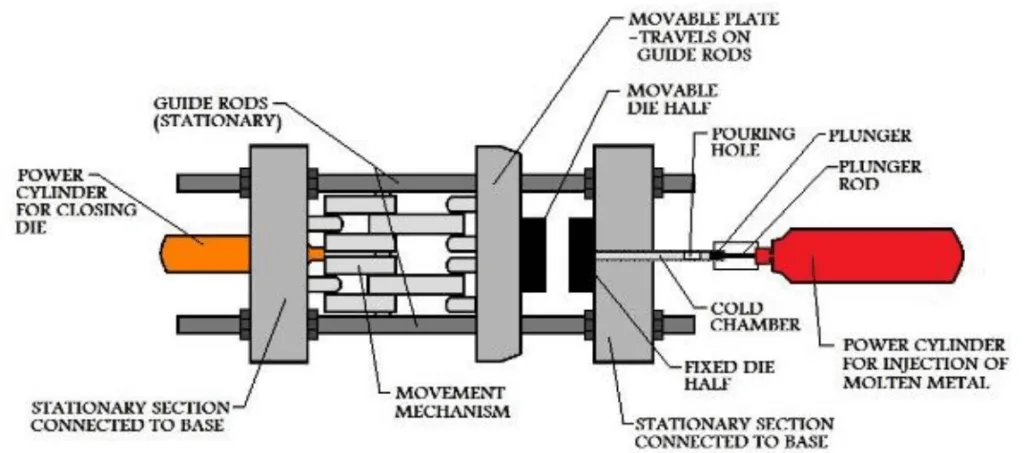
키워드
- 주요 키워드: HPDC 다이 설계
- 보조 키워드: 적층 제조, 열 응력, MAGMA 시뮬레이션, ABAQUS 시뮬레이션, 경량 다이, 컨포멀 쿨링
Executive Summary
- 도전 과제: 적층 제조를 위해 설계된 경량의 박벽(thin-walled) HPDC 다이가 주조 사이클 동안 발생하는 극심한 열 및 기계적 부하를 견딜 수 있는가?
- 연구 방법: 기존의 솔리드 다이 설계와 경량 허니콤 구조 설계를 비교하기 위해 주조 시뮬레이션(MAGMAsoft)과 열 응력 해석(Abaqus)을 결합한 통합 시뮬레이션 접근법을 사용했습니다.
- 핵심 발견: 경량 허니콤 설계는 냉각 성능을 향상시키고 사이클 타임을 단축시켰으나, 재료의 항복 강도를 초과하는 높은 응력으로 인해 구조적으로 실패한 반면, 기존 설계는 안전 한계 내에서 안정성을 유지했습니다.
- 핵심 결론: 단순한 박벽 구조를 통한 경량화는 추가적인 최적화 없이는 실행 불가능하지만, 본 연구는 향상된 냉각 성능의 가능성을 입증하고 향후 최적화된 설계를 위한 강력한 시뮬레이션 방법론을 제시합니다.
도전 과제: 이 연구가 HPDC 전문가에게 중요한 이유
고압 다이캐스팅(HPDC) 산업에서 다이 제작은 긴 리드 타임과 높은 초기 비용이라는 고질적인 문제를 안고 있습니다. 기존의 절삭 가공 방식은 복잡한 형상 구현에 한계가 있어, 특히 효율적인 냉각을 위한 컨포멀 쿨링 채널(conformal cooling channels) 설계에 제약이 많습니다.
적층 제조(AM), 즉 3D 프린팅 기술은 이러한 제약을 극복할 잠재력을 가지고 있습니다. 설계 자유도를 극대화하여 복잡한 내부 구조를 구현하고, 이를 통해 다이의 성능을 최적화할 수 있기 때문입니다. 하지만 AM 기술의 가장 큰 장벽 중 하나는 높은 비용입니다. 재료 사용량과 프린팅 시간이 비용과 직결되므로, 다이를 최대한 가볍게 설계하는 것이 경제성 확보의 핵심입니다.
여기서 근본적인 질문이 제기됩니다: "과연 AM을 위해 질량을 줄인 경량 다이가 HPDC 공정의 가혹한 고온, 고압 환경을 견딜 수 있을까?" 이 연구는 바로 이 질문에 대한 답을 찾기 위해 시작되었습니다. 경량화가 가져오는 경제적 이점과 구조적 안정성 사이의 균형점을 찾는 것은 HPDC 산업의 차세대 혁신을 위해 반드시 해결해야 할 과제입니다.
접근 방식: 연구 방법론 분석
본 연구는 두 가지 다이 설계 변형에 대한 성능을 비교하기 위해 다단계 시뮬레이션 접근법을 채택했습니다. 이 방법론은 실제 다이 제작에 앞서 설계의 타당성을 정밀하게 검증하는 데 목적이 있습니다.
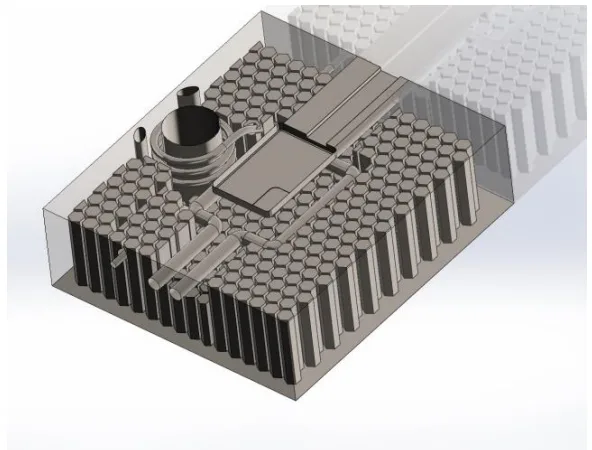
방법 1: 두 가지 다이 설계 모델링 (SolidWorks) - 초기 설계 (Initial Design): 기존의 절삭 가공 방식을 기반으로 한 전통적인 솔리드(solid) 형태의 다이 인서트입니다. 전체가 꽉 찬 구조로, 기계적 강성은 높지만 무겁고 열 방출이 비효율적일 수 있습니다. - 최종 설계 (Final Design): 적층 제조에 최적화된 경량 설계입니다. 다이 내부에 허니콤(honeycomb) 구조를 적용하여 질량을 획기적으로 줄이고, 컨포멀 쿨링 채널을 통합하여 냉각 효율을 높이도록 설계되었습니다.
방법 2: HPDC 공정 시뮬레이션 (MAGMAsoft) - 두 설계 모델을 사용하여 단일 HPDC 사이클(충전, 응고, 취출)을 시뮬레이션했습니다. 이 과정을 통해 다이와 주조품의 시간에 따른 온도 변화 이력 데이터를 확보했습니다. MAGMAsoft는 주조 공정의 열 전달 계수(HTC) 데이터베이스를 활용하여 실제와 유사한 열적 거동을 정밀하게 예측합니다.
방법 3: 열 응력 해석 (ABAQUS) - MAGMAsoft에서 얻은 온도 이력 데이터를 ABAQUS의 유한 요소 모델(FEM)에 매핑했습니다. 이 온도 분포를 기반으로 다이 내부에 발생하는 열 응력(thermal stresses)과 기계적 부하로 인한 응력을 계산하여, 다이가 구조적으로 안전한지, 소성 변형이 발생하는지를 분석했습니다.
핵심 발견: 주요 결과 및 데이터
시뮬레이션 결과는 경량 설계의 잠재력과 명확한 한계를 동시에 보여주었습니다.
결과 1: 냉각 성능 향상 및 사이클 타임 단축
경량 허니콤 구조와 컨포멀 쿨링 채널을 적용한 '최종 설계'는 '초기 설계'에 비해 월등한 냉각 성능을 보였습니다. 아래 그래프(Figure 4.25, 4.28)에서 볼 수 있듯이, 최종 설계는 주조품과 다이 모두를 더 빠르게 냉각시켜 전체 사이클 타임을 약 2초 단축시키는 결과를 가져왔습니다. 이는 대량 생산 환경에서 생산성 향상에 직접적으로 기여할 수 있는 매우 의미 있는 개선입니다.
결과 2: 응력 집중 및 구조적 실패
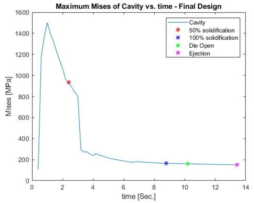
하지만 구조적 안정성 측면에서는 정반대의 결과가 나타났습니다. - 초기 설계: 시뮬레이션 결과, 최대 응력은 약 1125 MPa로 측정되었으며, 이는 사용된 다이 소재의 항복 강도(1480 MPa)보다 훨씬 낮아 충분한 안전성을 확보했음을 의미합니다 (Figure 4.31). - 최종 설계: 반면, 경량화를 위해 적용된 얇은 허니콤 벽 구조는 HPDC 공정의 극심한 열 및 기계적 부하를 견디지 못했습니다. 캐비티(Cavity) 측에서 최대 2745 MPa에 달하는 응력이 발생했으며, 이는 항복 강도를 크게 초과하는 수치로, 실제 공정에서 다이가 파손될 것임을 시사합니다 (Figure 4.34).
R&D 및 운영을 위한 실질적 시사점
이 연구 결과는 HPDC 공정, 품질, 설계 엔지니어에게 다음과 같은 중요한 통찰을 제공합니다.
- 공정 엔지니어: 적층 제조를 통한 컨포멀 쿨링은 사이클 타임 단축에 매우 효과적일 수 있습니다. 하지만 다이의 구조적 무결성이 확보되지 않으면 이점을 활용할 수 없으므로, 경량 설계 시 응력 분석이 반드시 선행되어야 합니다.
- 품질 관리팀: MAGMAsoft와 ABAQUS를 연동하는 시뮬레이션 방법론은 다이 제작 전에 잠재적인 파손 부위를 예측하는 강력한 도구가 될 수 있습니다. 이를 통해 프로토타입 제작 비용과 시간을 절감하고 다이의 수명을 예측하는 데 활용할 수 있습니다.
- 설계 엔지니어: 단순히 질량을 줄이기 위해 내부를 비우거나 얇은 벽 구조를 사용하는 것은 위험합니다. 허니콤 구조의 벽 두께를 최적화하거나, 응력이 집중되는 부위를 보강하는 등 반복적인 해석과 위상 최적화(topology optimization)를 통해 강성과 경량화의 균형을 맞추는 설계 전략이 필요합니다.
논문 상세 정보
HPDC Die design for Additive Manufacturing: Simulation and Comparison of Thermal Stresses in HPDC die designed for Additive Manufacture
1. 개요:
- 제목: HPDC Die design for Additive Manufacturing: Simulation and Comparison of Thermal Stresses in HPDC die designed for Additive Manufacture
- 저자: Mohammadali Baradaran and Ambareeksh Tharayil Pradeep
- 발표 연도: 2018년 12월
- 발표 기관: Jönköping University, School of Engineering
- 키워드: HPDC, Additive manufacturing, MAGMA simulation, Structural analysis, Casting Dies, ABAQUS simulation, Expansion, Die Life, HTC, Cooling Curves
2. 초록:
적층 제조(AM)는 리드 타임을 상당히 단축하고 기존 제조 기술의 설계 복잡성 한계를 극복함으로써 다이 제조에 큰 이점을 제공할 잠재력을 가지고 있습니다. 그러나 AM은 공정 한계를 고려하는 '적층 제조를 위한 설계(Design for Additive Manufacturing)'라는 고유의 요구사항을 가집니다. 중요한 요구사항 중 하나는 설계의 질량 효율성(가능한 한 가벼워야 함)입니다. 이 요구사항이 충족되지 않으면, AM은 뛰어난 이점에도 불구하고 경제적인 해결책이나 대체재가 될 수 없습니다. 본 연구는 이러한 우려를 바탕으로 구성되었습니다.
본 연구는 두 가지 설계 변형의 성능을 비교하고자 합니다. 또한, 사용된 방법을 연구하고, 접근법의 구현을 문서화하며, 적층 제조를 위한 설계와 관련된 과제를 식별하고자 했습니다.
고압 다이캐스팅(HPDC) 한 사이클 동안 주어진 부품에 대해 다이 인서트에서 발생하는 열 응력 시뮬레이션을 제시합니다. 초기 다이 인서트 설계는 허니콤 구조를 통합하여 질량 감소를 의도로 재설계되었습니다. 재설계된 모델의 온도 변화와 그에 따른 열 응력을 분석하고 원래 설계와 비교합니다.
HPDC 시뮬레이션은 MagmaSoft에서 수행하여 다이 인서트와 주조품의 온도 이력을 얻었습니다. 암시적 비선형 탄성 완전 연성 열-변위 모델이 Abaqus에서 설정되었으며, Magma 결과가 응력 계산을 위한 입력으로 사용되었습니다.
결과에 따르면, 우리의 특정 설계에서 얇은 벽 구조를 가진 HPDC 다이는 열 및 기계적 부하를 견딜 수 없습니다. 그러나 반복적인 분석과 적절한 위상 최적화를 통해 경량의 복잡한 형상 다이를 성공적으로 제작할 수 있습니다.
3. 서론:
적층 제조(AM)는 재료를 층층이 쌓아 원하는 형상의 부품을 만드는 기술로, 1980년대에 개발된 이후 주로 신속 프로토타이핑에 사용되었습니다. 상당한 기술 발전에도 불구하고, AM은 중대량 생산에서 사출 성형이나 고압 다이캐스팅(HPDC)과 같은 기존 제조 기술과 경쟁하기 어렵습니다. 이는 높은 초기 설비 비용, 고가의 재료, 느린 공정 시간 때문입니다.
그러나 최근 AM은 대량 맞춤화(mass customization) 분야에서 주목받고 있으며, 기존 기술을 보완하는 강력한 수단으로 자리 잡고 있습니다. 특히 AM은 기존의 절삭 가공 방식의 제약에서 벗어나 설계 자유도를 극대화합니다. 대표적인 예로, 사출 성형 금형에 컨포멀 쿨링 채널을 적용하여 부품 품질을 개선하고 사이클 타임을 최대 50%까지 단축시킨 사례가 있습니다.
이러한 잠재력에도 불구하고, AM 기술을 공구 및 다이 제작에 도입하는 데는 어려움이 있습니다. 특히 AM의 비용 효율성은 질량, 즉 프린팅 시간에 크게 좌우됩니다. 따라서 AM의 이점을 최대한 활용하려면 위상 최적화 구조, 격자 구조, 허니콤 구조 등을 통해 부품을 최대한 가볍게 설계해야 합니다. 본 연구는 HPDC 다이 인서트를 경량화하여 재설계하고, 이 경량 다이가 주조 공정의 열 및 기계적 부하를 견딜 수 있는지 시뮬레이션을 통해 검증하는 것을 목표로 합니다.
4. 연구 요약:
연구 주제의 배경:
HPDC 다이 제조는 긴 리드 타임과 높은 비용, 그리고 기존 가공 방식의 설계 제약이라는 문제점을 안고 있습니다. 적층 제조(AM)는 컨포멀 쿨링 채널과 같은 복잡한 형상을 구현하여 이러한 문제들을 해결할 잠재력을 지니고 있으나, AM 자체의 높은 비용을 상쇄하기 위해서는 다이의 경량화가 필수적입니다.
이전 연구 현황:
이전 연구들은 주로 사출 성형 금형에 AM 기술을 적용하여 컨포멀 쿨링의 효과를 입증하는 데 집중되었습니다. HPDC와 같이 훨씬 더 높은 온도와 압력을 견뎌야 하는 금속 주조용 다이에 대한 AM 적용, 특히 경량 구조의 기계적 건전성에 대한 연구는 상대적으로 부족한 실정입니다.
연구 목적:
본 연구의 핵심 질문은 "적층 제조를 위해 설계된 얇은 벽 구조의 경량 HPDC 다이가 주조 사이클 동안 작용하는 열 및 기계적 부하를 견딜 수 있는가?"입니다. 이를 검증하기 위해 기존의 솔리드 다이 설계와 경량 허니콤 구조 설계를 시뮬레이션을 통해 비교 분석하는 것을 목적으로 합니다.
핵심 연구:
본 연구는 두 가지 설계안(초기 설계, 최종 설계)에 대한 비교 분석을 중심으로 진행됩니다. 1. 설계: 솔리드웍스(SolidWorks)를 사용하여 전통적인 솔리드 다이 인서트(초기 설계)와 내부 허니콤 구조 및 컨포멀 쿨링 채널을 포함한 경량 다이 인서트(최종 설계)를 모델링합니다. 2. 열 해석: 마그마소프트(MAGMAsoft)를 사용하여 HPDC 공정을 시뮬레이션하고, 두 설계안에 대한 시간에 따른 온도 분포 데이터를 추출합니다. 3. 구조 해석: 하이퍼메시(Hypermesh)로 유한 요소 메쉬를 생성한 후, 아바쿠스(Abaqus)에서 마그마소프트의 온도 데이터를 적용하여 열 응력 해석을 수행합니다. 이를 통해 각 설계안의 최대 응력 값을 계산하고 재료의 항복 강도와 비교하여 구조적 파손 여부를 평가합니다.
5. 연구 방법론
연구 설계:
본 연구는 두 가지 설계 변형(전통적 설계 vs. 경량 설계)의 성능을 비교하는 시뮬레이션 기반의 비교 연구로 설계되었습니다. '초기 설계(Initial Design)'는 전통적인 솔리드 블록 형태의 다이 인서트를 대표하며, '최종 설계(Final Design)'는 적층 제조를 위해 허니콤 구조로 경량화되고 컨포멀 쿨링 채널이 추가된 다이 인서트를 대표합니다.
데이터 수집 및 분석 방법:
- CAD 모델링: SolidWorks를 사용하여 주조 부품 및 두 가지 다이 인서트(초기 및 최종 설계)의 3D 모델을 생성했습니다.
- 주조 공정 시뮬레이션: MAGMAsoft를 사용하여 HPDC 공정의 충전 및 응고 단계를 시뮬레이션했습니다. 이를 통해 다이 인서트의 모든 노드에서 시간에 따른 온도 변화 이력(temperature history)을 획득했습니다.
- 메싱: Hypermesh를 사용하여 ABAQUS 해석을 위한 고품질 3D 사면체(tetrahedral) 메쉬를 생성했습니다.
- 열-기계 연성 해석: ABAQUS에서 완전 연성 열-변위(fully coupled thermal-displacement) 해석을 수행했습니다. MAGMAsoft에서 얻은 온도 데이터를 각 시간 스텝별로 ABAQUS 모델에 사전 정의된 필드(predefined field)로 적용하여, 열팽창으로 인한 응력과 기계적 하중(체결력)에 의한 응력을 동시에 계산했습니다.
연구 주제 및 범위:
본 연구는 단일 주조 사이클 동안 HPDC 다이 인서트에 발생하는 열 응력에 초점을 맞춥니다. 수만 회 반복되는 사이클에서 발생하는 열 피로(thermal fatigue) 효과는 본 연구의 범위에 포함되지 않습니다. 또한, 다이의 질량 감소가 용탕의 유동 및 충전 거동에 미치는 영향 역시 분석 대상에서 제외하고 열 및 기계적 해석에 집중했습니다.
6. 주요 결과:
주요 결과:
- 냉각 성능: 최종 설계(경량 허니콤 구조)는 초기 설계(솔리드 구조)에 비해 주조품과 다이 모두에서 더 빠른 냉각 속도를 보였습니다. 이로 인해 전체 사이클 타임이 약 2초 단축되었습니다.
- 구조적 안정성 (초기 설계): 초기 설계의 최대 Von Mises 응력은 약 1125 MPa로, 다이 소재의 항복 강도(1480 MPa)보다 현저히 낮아 구조적으로 안정적인 것으로 나타났습니다.
- 구조적 안정성 (최종 설계): 최종 설계는 캐비티에서 최대 2745 MPa, 코어에서 최대 1501 MPa의 응력을 보였습니다. 두 값 모두 재료의 항복 강도를 크게 초과하여, 해당 설계가 실제 공정에서 소성 변형 및 파손을 겪을 것임을 시사합니다.
- 결론: 얇은 벽으로 구성된 경량 허니콤 구조는 HPDC 공정의 부하를 견디지 못하고 실패했습니다. 그러나 냉각 성능 향상이라는 긍정적인 결과를 통해, 벽 두께를 최적화하는 등의 추가적인 설계를 통해 성공적인 경량 다이를 제작할 수 있는 가능성을 확인했습니다.
Figure Name List:
- Figure 1.1: Layout of Steps
- Figure 2.1: Die Slabs containing Die insert
- Figure 2.2 Hot Chamber HPDC setup
- Figure 2.3 Cold Chamber HPDC Setup
- Figure 2.4: Variation of IHTC value with time and temperature
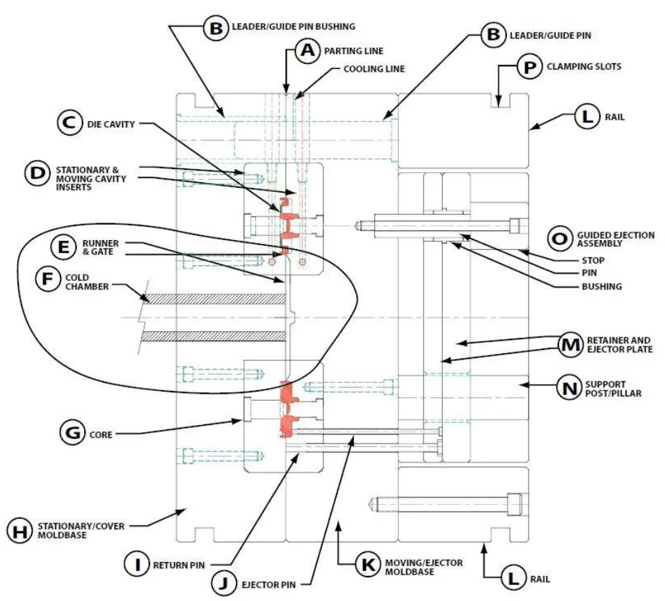
- Figure 2.5: HPDC die components
- Figure 2.6- Procedure of Die design
- Figure 2.7: Selective laser Melting
- Figure 2.8: Build orientation in 3Dprinting
- Figure 3.1 : Flow of the work
- Figure 3.2 : Component - Top view.
- Figure 3.3 : Component - Bottom view.
- Figure 3.4 : Component - Isometric view, left angle.
- Figure 3.5 : Component - Isometric view, right angle.
- Figure 3.6 : Component - Sectioned view, right angle.
- Figure 3.7 : Component - Sectioned view - left angle.
- Figure 3.8 : Core (Ejector die) – Top view.
- Figure 3.9 : Core (Ejector die) – Isometric view.
- Figure 3.10 : Cavity (Cover die) – Top view.
- Figure 3.11 : Cavity (Cover die) – Isometric view.
- Figure 3.12 : Bottom view of new core with honecomb structure.
- Figure 3.13 : Transparent top view of core with honeycomb structure showing the relative position of cooling channels.
- Figure 3.14 : Left view of core with honeycomb structure showing depth of the honeycom cells.
- Figure 3.15 : Isometric view of core with honeycomb structure showing depth of the cells around coolling channles. Transparent regions are solid structure.
- Figure 3.16 : Top isometric view of cavity with honeycomb structure.
- Figure 3.17 : Bottom view of cavity with honeycomb structure.
- Figure 3.18 : Transparent top view of cavity with honeycomb structure showing the position of cooling channels around the cavity and around the inlet.
- Figure 3.19 : Transparent top isometric view of cavity with honeycomb structure showing depth of the honeycomb cells around cooling channels. Transparent regions are solid structure.
- Figure 3.20 : Transparent left view of cavity with honeycomb structure showing depth of the honeycomb cells. Transparent regins are solid structure.
- Figure 3.21 : Closer transparent view of cavity with honeycomb structure.
- Figure 3.22 : Assembly of cating materials inside Magma geometry panel. From left to right: biscuite and inlet, runner, cast (component), overflow channel.
- Figure 3.23 : Side view of casting materials assembly in Magma and their relative positions.
- Figure 3.24 : Final Assembly in Magam. Top half represents cavity (cover die) containing inlet, biscuite, cast and one set of cooling channels. Bottom half represents core (ejector die) containing runner, overflow channel, ejector pins and one set of cooling channel.
- Figure 3.25 : Geometry tree.
- Figure 3.26 : Mesh of the ejector die.
- Figure 3.27 : Mesh of casting materials and ejector die.
- Figure 3.28 : Mesh of the casting materials.
- Figure 3.29 : Material definition window and defined settings.
- Figure 3.30 : Heat transfer definition window.
- Figure 3.31 : Process timeline for a HPDC cycle.
- Figure 3.32 : Events and sub-events of a casting cycle.
- Figure 3.33 : Active shot chamber length.
- Figure 3.34 : positio of plunger in shot sleeve when port is covered.
- Figure 3.35 : Shot curve definition panel.
- Figure 3.36 : Filling shot curve.
- Figure 3.37 : Intensification difinition window.
- Figure 3.38 : Die open definition window.
- Figure 3.39 : Dir tempering control window.
- Figure 3.40 : Results order condistion window.
- Figure 3.41: Top view from assembly of component, air pockets, and cooling channels in core.
- Figure 3.42 : Isometric view from assembly of component, air pockets, and cooling channels in core.
- Figure 3.43 : Assembly of air pockets and cooling channels in cavity.
- Figure 3.44 : Position of inserts in surrounding walls – Final design.
- Figure 3.45 : Mesh for the new cavity - Top.
- Figure 3.46 : Mesh for the new cavity – Bottom.
- Figure 3.47 : Mesh for the new core – Bottom.
- Figure 3.48 : Material definition window – Final design.
- Figure 3.49 : Heat transfer definition window for final design.
- Figure 3.50 : Size and bias panel of 2D auto meshing.
- Figure 3.51: Small features on core that need finer mesh than sorrounding areas.
- Figure 3.52 : Small feature shown in Figure 3.51 from different angle.
- Figure 3.53 : Surface deviation panle of 2D automeshing.
- Figure 3.54 : Mesh transition on core.
- Figure 3.55 : Check element tab where element quality check can be carried out for 2D and 3D mesh.
- Figure 3.56 : Edge panel where operation for finding free edges and T-connections is carried out.
- Figure 3.57 : Tetramesh control panel of tetramesh in 3D meshing.
- Figure 3.58 : tetramesh control panel for executing 3D mesh creation. 2D mesh is selected as input for Fixedtrias/quads to tetramesh.
- Figure 3.59 : Meshed cavity, final design, top view.
- Figure 3.60 : Meshed cavity, final design, side view.
- Figure 3.61 : Meshed cavity, final design, bottom view.
- Figure 3.62 : a sectioned view showing the solid elements, cavity, final design.
- Figure 3.63 : Side sectioned view showing solid elements, cavity, final design.
- Figure 3.64 : Meshed core, top view, final design.
- Figure 3.65 : Meshed core, showing mesh transition, final design.
- Figure 3.66 : Meshed core, bottom view, new design.
- Figure 3.67 : Meshe core, bottom view, closer look, final design.
- Figure 3.68 : Sectined view of core showing solid element, final deesign.
- Figure 3.69 : Sectined view of core showing solid element, final deesign.
- Figure 3.70 : Meshed cavity, top view, initial design.
- Figure 3.71 : Meshed cavity, isometric top view, initial design.
- Figure 3.72 : Meshed cavity, bottom view, initial design.
- Figure 3.73 : Sectioned view of cavity shoeing solid elements, initial design.
- Figure 3.74 : Meshed core, top view initial design.
- Figure 3.75 : Meshed core, isometri top view, initial design.
- Figure 3.76 Sectined view of core showing solid elements, initrial design.
- Figure 3.77 : Solver deck export panel for mesh export in HyperMesh.
- Figure 3.78 : Entity State panel where components of interest can be selected for mesh export.
- Figure 3.79 : Model tree view in Abaqus.
- Figure 3.80 : Part copy window where joint parts in assembly can be detached.
- Figure 3.81 : Assembly in Abaqus.
- Figure 3.82 : Basic tab of step definition window in Abaqus.
- Figure 3.83 : Increment tab of step definition in Abaqus.
- Figure 3.84 : Die movment constrained along X axis.
- Figure 3.85 : Die Movement constrained alonf Y axix.
- Figure 3.86 : Bottom surface of the cavity is pinned. Movement of die inserts along Z axis is restricted.
- Figure 3.87 : Defining a uniform load applied on the top of the core.
- Figure 3.88 : Defining the contact surface in interaction module.
- Figure 3.89 : Definition of tangential behaviour in interaction properties.
- Figure 3.90 : Definition of normal behaviour in interaction properties.
- Figure 3.91: Assigning initial temperature of the inserts in predefined field.
- Figure 3.92 : Export file window in Magma.
- Figure 3.93 : Material selection window in Magma.
- Figure 3.94 : Results category selection for export in Magma.
- Figure 3.95 : An example of temperature file generated by result export in Magma (Left). Same temperature file after being modified by MATLAB.
- Figure 4.1 : Temperature profile of core at the end of filling (0.38 s, Max Temp = 178 ºC).
- Figure 4.2 : Temperature profile of core at 50% solidification (t = 2.2 s, Max T= 359 ºC).
- Figure 4.3 : Temperature profile of core at 100% solidification (t = 8.91 s, Max T= 348 ºC).
- Figure 4.4 : Temperature profile of core at die open (t = 10.12 s, Max T= 327 ºC).
- Figure 4.5 : Temperature profile of core at ejection (t = 15.14 s, Max T= 223 ºC).
- Figure 4.6 Temperature profile of cavity at the end of filling (t = 0.38 s, Max T= 170 ºC).
- Figure 4.7 Temperature profile of cavity at 50% solidification (t = 2.2 s, Max T= 367 ºC).
- Figure 4.8 Temperature profile of cavity at 100% solidification (t = 8.91 s, Max T= 310 ºC).
- Figure 4.9 Temperature profile of cavity at die open (t = 10.12 s, Max T= 298 ºC).
- Figure 4.10 Temperature profile of cavity at ejection (t = 15.14 s, Max T= 215 ºC).
- Figure 4.11 Temperature profile of core at 50% solidification (t = 1.80 s, Max T= 361 ºC).
- Figure 4.12 Temperature profile of core at 100% solidification (t = 7.35 s, Max T= 367 ºC).
- Figure 4.13 Temperature profile of core at die open (t = 8.44 s, Max T= 348 ºC).
- Figure 4.14 Temperature profile of core at ejection (t = 13.45 s, Max T= 251 ºC).
- Figure 4.15 Temperature profile of core at 50% solidification (t = 1.80 s, Max T= 385 ºC).
- Figure 4.16 Temperature profile of core at 100% solidification (t = 7.35 s, Max T= 322 ºC).
- Figure 4.17 Temperature profile of core at die open (t = 8.44 s, Max T= 306 ºC).
- Figure 4.18 Temperature profile of cavity at ejection (t = 13.45 s, Max T= 194 ºC).
- Figure 4.19 : Cooling behavior of cavity- initial design.
- Figure 4.20 : Cooling behavior of core- initial design.
- Figure 4.21 : Superimposed cooling behaviors of cavity and core - initial design.
- Figure 4.22 : Cooling behavior of cavity- final design.
- Figure 4.23 : Cooling behavior of core- final design.
- Figure 4.24 : Superimposed cooling behaviors of cavity and core – final design.
- Figure 4.25 : Superimposed cooling behaviors of cavity and core – initial and final design (new design).
- Figure 4.26 : Cooling behavior of cast in initial design.
- Figure 4.27 : Cooling behaviour of cast in final design (new design).
- Figure 4.28 : Superimposed cooling behaviors of cast in initial and final design (new design).
- Figure 4.29 : Unaveraged maximum mises stress Vs. time for cavity initial design.
- Figure 4.30 : Unaveraged maximum mises stress Vs. time for core initial design.
- Figure 4.31 : Superimposed unaveraged maximum mises stresses of core and cavity – Initial design.
- Figure 4.32 : Unaveraged maximum mises stress Vs. time for cavity Final design
- Figure 4.33 : Unaveraged maximum mises stress Vs. time for core Final design.
- Figure 4.34 : Superimposed unaveraged maximum mises stresses of core and cavity – Final design
7. 결론:
본 논문에서 분석된 최종 설계(경량 다이)는 주조 사이클 동안 실패했습니다. 사이클 동안 유도된 높은 응력 값이 본 연구에 사용된 재료의 항복 강도보다 높았기 때문입니다.
그러나 최종 설계는 주조품과 다이 모두의 냉각 거동에서 개선을 보였습니다. 최종 설계에서 발생한 높은 응력은 더 효과적인 냉각 덕분에 더 빨리 소산되었습니다. 또한, 최종 설계의 코어에서 캐비티에 비해 훨씬 더 높은 응력 변화가 관찰되었습니다.
결론적으로, 얇은 벽의 두께를 증가시킴으로써 최종 설계를 높은 응력을 견딜 수 있도록 만들 수 있습니다. 새로운 설계로 인한 질량 감소가 가열 사이클에 의해 생성된 응력을 감당할 수 있는지 확인하는 것이 중요합니다.
8. 참고 문헌:
- [1] M. Attaran, ”The rise of 3-D printing: The advantages of additive anufacturing over traditional manufacturing,” Elsevier, p. 12, 2017.
- [2] Charisios Achillas, Dimitrios Tzetzis & Maria Olga Raimondo, ”Alternative production strategies based on the compaison of additive and traditional manufacturing technologies,” International Journal of Production Research, vol. 55, pp. 3497-3509, 2017.
- [3] Christoph Klahn, Bastian Leutenecker, Mirko Meboldt, ”Design Strategies for the process of additive manufacturing,” Elsevier , pp. 230-235, 2015.
- [4] T. Vaneker, ”The role of design for additive manufacturing in the successful economical introduction of AM,” Elsevier, pp. 181-186, 2017.
- [5] Mahmoud Dinar, David W. Rosen, ”A design for additive manufacturing ontology,” Journal of compting and information sience in engineering , vol. 17, p. 9, 2017.
- [6] Sebastian Hällgren, Lars Pejryd, Jens Ekengren, ”(Re)Design for additive manufacturing,” Elsevier , pp. 246-251, 2016.
- [7] Kranz, H. D och E. C, ”Design guidelines for laser additive manufacturing of light weight structures in TiAl6V4,” Journal of Laser applications, 2016.
- [8] R. Leal, F.M. Barreiros, L. Alves, F. Romeiro, J. C. Vasco, M. Santos, ”Additive manufacturing tooling for automotive industry,” Journal of advanced manufacturing technology , pp. 1671-16-76, 2017.
- [9] Konstantinos Salonitis, Saeed Al Zarban, ”Redesign optimization for manufaturing using additive layer techniques,” Elsevier, pp. 193-198, 2015.
- [10] B. Andresen, Die Casting Engineering- A hydraulic, thermal and mchanical process, New York: Marcel Dekker, 2005.
- [11] M.Winkler, L. Kallien och T. Feyertag, ”Correlation between process parameters and quality charecterestics in aluminum high pressure die casting,” North American Die Casting Association, 2015.
- [12] P. Senthiil, M. Chinnapandian och A. Sirrussshti, ”Optimization of process parameters in cold chamber die casting process using Taguchi Method,” International Journal of innovative science, vol. 1, nr 6, 2014.
- [13] M. S. Dargusch, A. Hamasaiid, G. Dour, T. Loulou, C. J. Davidson och D. H.StJohn, ”The Accurate Determination of Heat Transfer Coefficient and its Evolution with Time During High Pressure Die Casting of Al‐9 %Si‐3 %Cu and Mg‐9 %Al‐1 %Zn Alloys,” Advanced Engineering Materials, p. 997, 2007.
- [14] R. Ranjan, R. Samant och S. Anand, ”Integration of Design for Manufacturing Methods with Topology Optimisation in Additive Manufacturing,” Journal of Manufacturing Science and Engineering, vol. 139, nr 6, 2016.
- [15] A. Rosochowski A., ”Rapid Tooling: The State of the Art,” Journal of Material Processing technology, vol. 106, pp. 191-198, 2000.
- [16] D. T, J. Zuback, H. Wei, T. Mukerjee, E. J.W., M. J.O., B. A.M., A. Wilson-Heid, A. De och W. Zhang, ”Additive manufacture of metallic components,” Progress in Materials Science, vol. 92, pp. 112-224, 2018.
- [17] R. Stolt, S. Andre och F. Elgh, ”Introducing Inserts for Die casting manufactured by Selective Laser Sintering,” Procedia Manufacturing, 2018.
- [18] C. K. Mario Valdez, E. J. Faierson och . I. Jasiuk, ”Induced porosity in Super alloy718 through the laser additive manufacturing process: Microstructure and Mechanical Properties,” Journal of Alloys and Compounds, pp. 757-764, 2017.
- [19] M. JO, ”Additive Manufacture of metals,” Springer series in Material science, vol. 258, 2017.
- [20] A. KN, G. SM, M. LE, M. E, S. PW och H. J, ”Microstructures and mechanical properties of Inconel 718 fabricated by selective laser melting,” Acta Mater , pp. 2229-2239, 2012.
- [21] C.-C. Kuo och M.-R. Li, ”Development of sheet metal forming dies with excellent mechanical properties using additive manufacturing and rapid tooling technologies,” Journal of Advanced Engineering Materials, vol. 90, pp. 21-25, 2017.
- [22] P. HS och P. NH, ”Design of conformal cooling channels for an automotive part,” International Journal of automotive technology, vol. 10, nr 1, pp. 87-93, 2009.
- [23] A. Armillotta, R. Baraggi och S. Fasoli, ”SLM tooling for die casting with conformal cooling channels,” International Journal of Advanced Manufacturing Technology, vol. 71, pp. 573-583, 2014.
전문가 Q&A: 자주 묻는 질문
Q1: 경량 설계를 위해 특별히 허니콤 구조를 선택한 이유가 무엇인가요?
A1: 논문에 따르면, 허니콤 구조는 뛰어난 중량 대비 강성 비율과 우수한 면외(out-of-plane) 압축 및 전단 특성으로 인해 샌드위치 패널의 코어 재료로 널리 사용됩니다. 이러한 특성은 다이의 전체적인 질량을 줄이면서도 필요한 구조적 지지력을 제공할 수 있을 것이라는 기대를 바탕으로 선택되었습니다.
Q2: 경량 설계에서 구조적 실패가 발생한 주된 원인은 무엇이었나요?
A2: 실패의 주된 원인은 허니콤 구조를 형성하는 벽이 너무 얇았기 때문입니다. 논문의 결론에 따르면, 이 얇은 벽들은 HPDC 공정 중 발생하는 극심한 열 응력과 기계적 응력을 감당하기에 역부족이었습니다. 결과적으로 응력이 재료의 항복 강도를 초과하여 소성 변형 및 파손을 유발했습니다.
Q3: MAGMA에서 ABAQUS로 결과를 매핑하는 과정에서 발생할 수 있는 잠재적 오차 요인은 무엇인가요?
A3: 논문의 '토의 및 결론' 섹션에서는 몇 가지 오차 요인을 언급합니다. 가장 큰 요인은 두 소프트웨어 간의 메쉬 불일치입니다. MAGMA의 FDM(유한차분법) 격자와 ABAQUS의 FEM(유한요소법) 노드가 완벽하게 일치하지 않아 보간(interpolation) 과정에서 오차가 발생할 수 있습니다. 또한, FEM 노드 주변의 값을 찾기 위한 검색 반경(search radius)이 너무 크면 결과의 정확도가 떨어질 수 있습니다.
Q4: 구조적 실패에도 불구하고 새로운 경량 설계가 보여준 이점은 무엇이었나요?
A4: 가장 큰 이점은 냉각 성능의 현저한 개선입니다. 시뮬레이션 결과(Figure 4.25), 경량 설계는 주조품과 다이 모두의 냉각 속도를 높여 전체 사이클 타임을 약 2초 단축시켰습니다. 이는 대량 생산 환경에서 생산성을 크게 향상시킬 수 있는 중요한 잠재력을 의미합니다.
Q5: 이 연구를 바탕으로 미래의 적층 제조 다이 설계를 위한 핵심 교훈은 무엇인가요?
A5: 핵심 교훈은 경량화와 구조적 강성 사이의 균형을 찾는 것이 중요하다는 점입니다. 단순한 질량 감소는 실패로 이어질 수 있으므로, 설계 엔지니어는 반드시 반복적인 시뮬레이션과 위상 최적화를 수행해야 합니다. 논문은 허니콤 구조의 벽 두께를 늘리는 것만으로도 설계를 성공적으로 만들 수 있다고 제안하며, 이는 최적화된 설계가 충분히 실현 가능하다는 것을 시사합니다.
결론: 더 높은 품질과 생산성을 향한 길
본 연구는 적층 제조 기술을 활용한 HPDC 다이 설계의 현실적인 과제를 명확히 보여주었습니다. 단순한 경량화는 구조적 실패를 초래했지만, 동시에 컨포멀 쿨링을 통한 사이클 타임 단축이라는 확실한 가능성을 입증했습니다. 이 연구가 제시한 시뮬레이션 방법론은 향후 R&D 및 운영 과정에서 시행착오를 줄이고, 강성과 냉각 성능이 모두 최적화된 혁신적인 다이를 개발하는 데 중요한 기반이 될 것입니다.
"CASTMAN에서는 고객이 더 높은 생산성과 품질을 달성할 수 있도록 최신 산업 연구를 제품 개발에 적극적으로 적용하고 있습니다. 본문에 논의된 과제가 귀사의 운영 목표와 일치한다면, CASTMAN의 엔지니어링 팀에 연락하여 이러한 원칙을 귀사의 부품에 어떻게 구현할 수 있는지 논의해 보십시오."
저작권 정보
이 콘텐츠는 "HPDC Die design for Additive Manufacturing" (저자: Mohammadali Baradaran, Ambareeksh Tharayil Pradeep) 논문을 기반으로 한 요약 및 분석 자료입니다.
출처: Jönköping University, School of Engineering, December 2018
이 자료는 정보 제공 목적으로만 사용됩니다. 무단 상업적 사용을 금합니다. Copyright © 2025 CASTMAN. All rights reserved.