클러치 허브 제조를 위한 압력 다이캐스팅 툴 설계: 정밀 계산부터 생산까지
이 기술 요약은 Akshay K. Khandagale이 작성하여 2022년 Journal Publication of International Research for Engineering and Management (JOIREM)에 게재한 학술 논문 "Design and Manufacture a Pressure Die Casting Tool for the manufacturing of the Clutch hub"을 기반으로 합니다. CASTMAN이 기술 전문가를 위해 분석하고 요약했습니다.
키워드
- Primary Keyword: 압력 다이캐스팅 툴 설계
- Secondary Keywords: 다이캐스팅, 클러치 허브 제조, 금형 설계, 다이캐스팅 공정, 주조 결함, 설계 계산
Executive Summary
- The Challenge: 영구 주조 방식으로는 생산하기 어려운 복잡한 형상의 클러치 허브를 높은 정밀도와 반복성으로 대량 생산할 수 있는 비용 효율적인 제조 솔루션이 필요합니다.
- The Method: 클러치 허브의 중량, 밀도, 투영 면적 등 핵심 데이터를 기반으로 형체력, 게이트 속도, 오버플로우 등 다이캐스팅 툴의 주요 파라미터를 체계적으로 계산하고, UNIGRAPHICS 및 AUTO-CAD를 사용하여 툴을 모델링했습니다.
- The Key Breakthrough: 본 연구는 클러치 허브의 투영 면적(176.62cm²)과 주조 압력(800kg/cm²)을 기반으로 최소 255톤의 형체력이 필요함을 계산하여, 특정 부품에 적합한 다이캐스팅 머신을 선정하는 구체적인 기준을 제시했습니다.
- The Bottom Line: 성공적인 압력 다이캐스팅 제품 생산은 부품의 특성에 기반한 정밀한 공학적 계산과 체계적인 공정 흐름 설계에 달려있습니다.
The Challenge: 왜 이 연구가 HPDC 전문가에게 중요한가
다이캐스팅은 금속가공 산업에서 대량 생산되는 핵심 품목 중 하나로, 자동차부터 장난감에 이르기까지 수많은 소비재, 상업 및 산업 제품의 중요 부품을 구성합니다. 특히 영구 주조가 중력에 의존하는 반면, 압력 다이캐스팅은 고압을 이용해 용탕을 고속으로 충전시키므로 훨씬 더 복잡한 형상의 부품을 정밀하게 생산할 수 있습니다. 클러치 허브와 같은 복잡한 자동차 부품을 높은 정확도와 반복성, 그리고 비용 효율성을 만족시키며 제조하기 위해서는 체계적인 압력 다이캐스팅 툴 설계가 필수적입니다. 이 연구는 바로 이 문제를 해결하기 위해 시작되었습니다.
The Approach: 방법론 분석
본 연구는 클러치 허브 제조를 위한 압력 다이캐스팅 툴을 설계하고 제조하는 전 과정을 다룹니다. 연구의 핵심은 다음과 같은 체계적인 접근 방식에 있습니다.
- 설계 계산: 먼저, 제조할 클러치 허브의 핵심 파라미터를 정의했습니다.
- 주조품 중량: 387.27gm
- 밀도: 2.7gm/cm³
- 부품 투영 면적: 176.62cm²
- 게이트 속도: 40 m/sec² 이 데이터를 기반으로 머신 형체력, 게이트 면적, 러너 및 오버플로우 시스템의 크기를 정밀하게 계산했습니다.
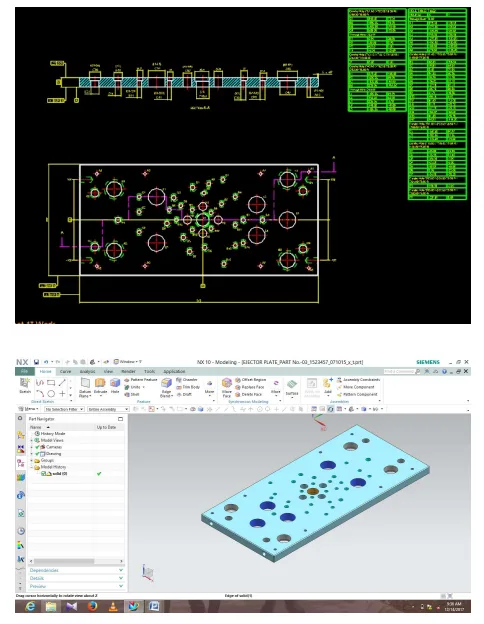
- 공정 흐름 설계: 견적부터 출하까지 이어지는 전체 제조 공정 흐름(Fig.-1)을 정의했습니다. 이 흐름에는 설계, 원자재 준비, 가공(선반, CNC, 연삭), 열처리, 조립 및 검사 단계가 포함됩니다.
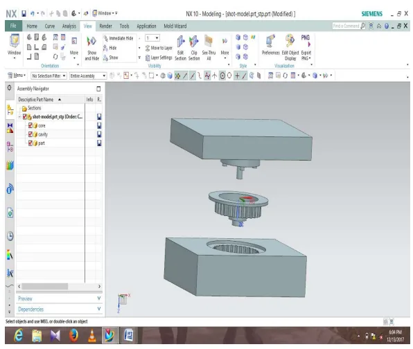
- 툴 모델링: AUTO-CAD와 UNIGRAPHICS(NX) 소프트웨어를 사용하여 금형의 다양한 구성 요소, 특히 코어와 캐비티(Fig -3)를 모델링했습니다. 이를 통해 설계의 정확성을 높이고 제조 오류를 최소화했습니다.
The Breakthrough: 주요 발견 및 데이터
본 연구는 성공적인 다이캐스팅 툴 설계를 위한 구체적인 계산 과정과 결과를 제시합니다.
Finding 1: 필수 형체력의 정밀 계산
성공적인 다이캐스팅을 위해 가장 중요한 요소 중 하나는 용탕 주입 시 금형이 열리는 것을 방지하는 충분한 형체력(Machine tonnage)을 확보하는 것입니다. 본 연구에서는 다음 공식을 사용하여 필요한 최소 형체력을 255톤으로 계산했습니다. * Tm = (As x Pc x fos) / 1000 * As (총 투영 면적): 264.92 cm² (부품 + 피드 시스템) * Pc (주조 압력): 800 kg/cm² * fos (안전 계수): 1.2 * Tm = (264.62 x 800 x 1.2) / 1000 = 254.32 Ton ≈ 255 Ton 이 계산을 통해 이 클러치 허브 부품 생산에 255톤급 다이캐스팅 머신이 적합하다는 명확한 근거를 마련했습니다.
Finding 2: 게이트, 러너, 오버플로우 시스템의 체계적 설계
주조 품질은 용탕이 캐비티로 흘러 들어가는 경로 설계에 크게 좌우됩니다. 본 연구는 다음과 같은 구체적인 설계 값을 도출했습니다. * 게이트(Gate): 충전 시간(0.08초)과 게이트 속도(40 m/s)를 고려하여 게이트 면적을 0.58 cm² (58.25 mm²)로 계산했으며, 게이트 두께는 2mm, 폭은 29.125mm로 설계했습니다. * 러너(Runner): 러너와 게이트의 면적 비율을 3:1로, 두께 비율을 8:1로 설정하여 용탕의 흐름을 최적화했습니다. * 오버플로우(Overflow): 캐비티 내 공기를 배출하고 완전한 충전을 돕기 위해 부품 면적의 30%에 해당하는 5200 mm²의 오버플로우를 설계했습니다. 이는 5개의 개별 오버플로우로 분할되었습니다.
Practical Implications for R&D and Operations
이 연구 결과는 다이캐스팅 현장의 여러 전문가에게 실질적인 통찰력을 제공합니다.
- 공정 엔지니어: 이 연구에서 제시된 형체력(255톤), 게이트 속도(40 m/s), 충전 시간(0.08초) 등의 계산 과정은 유사한 부품의 다이캐스팅 머신 셋업을 위한 실용적인 템플릿을 제공합니다.
- 품질 관리팀: 부품 면적의 30%에 달하는 오버플로우 설계는 주조품의 기공과 같은 내부 결함을 최소화하는 데 중요한 역할을 합니다. 이는 오버플로우의 충전 상태가 주조 품질을 판단하는 새로운 검사 기준이 될 수 있음을 시사합니다.
- 설계 엔지니어: 이 논문은 초기 부품 분석부터 게이팅, 러너, 오버플로우 시스템의 상세 계산에 이르기까지 압력 다이캐스팅 툴 설계의 단계별 가이드를 제공합니다. 특히 UNIGRAPHICS를 이용한 코어/캐비티 추출(Fig-3) 과정은 초기 설계 단계에서 오류를 줄이는 데 매우 유용합니다.
Paper Details
Design and Manufacture a Pressure Die Casting Tool for the manufacturing of the Clutch hub
1. Overview:
- Title: Design and Manufacture a Pressure Die Casting Tool for the manufacturing of the Clutch hub
- Author: Mr. Akshay K. Khandagale
- Year of publication: 2022
- Journal/academic society of publication: Journal Publication of International Research for Engineering and Management (JOIREM)
- Keywords: mould, casting
2. Abstract:
DIE CASTINGS are produced by forcing molten metal under pressure into metal mould called dies. Mould filling in permanent mould casting depends on the force of gravity, die casting involves metal flow at high velocities induced by the application of pressure. Because of this high velocity filling, die casting can produce shapes that are more complex than shapes that can be produced by permanent mould casting. In die casting, die has been closed and locked; molten metal is delivering through plunger or pump. The pump plunger is advanced to drive molten metal to quickly through the feeding system while the air in the die escapes through vents. Sufficient metal is introduced to over flow the die cavities, fill overflow wells and develop some flash. As the extraneous metal solidifies, pressure is applied to the remaining metal and is maintained through a specified dwell time to allow the casting to solidify. The die opens and the casting is then ejected. While the casting die is open, it is cleaned and lubricated as required. Then the die is closed and locked, and the cycle is repeated.
3. Introduction:
Die castings are among the highest volume, mass-produced items manufactured by the metalworking industry. They can be found in thousands of consumer, commercial and industrial products. Die cast parts are important components of products ranging from automotive to toys. Parts can be as simple as a handle or a complex engine block. A versatile process for producing engineered metal parts, die casting calls for forcing molten metal under high pressure into reusable steel molds. These molds, called dies, can be designed to produce complex shapes with a high degree of accuracy and repeatability. Parts can be sharply defined, with smooth or textured surfaces, and are suitable for a wide variety of attractive and serviceable finishes.
4. Summary of the study:
Background of the research topic:
The research focuses on pressure die casting, a process for manufacturing complex metal parts by injecting molten metal under high pressure into a reusable steel mold (die). This method is superior to permanent mold casting for creating intricate shapes with high accuracy and good surface finish, making it vital for industries like automotive.
Status of previous research:
The paper does not explicitly detail the status of previous research but builds upon established principles of die casting tool design, referencing existing literature on topics like casting defects, injection parameters, and process optimization.
Purpose of the study:
The purpose is to present a systematic approach to designing and manufacturing a pressure die casting tool specifically for a clutch hub. This involves detailing the necessary design calculations, process flow, and the use of CAD/CAM software to create a functional and efficient tool.
Core study:
The core of the study is the practical application of die casting theory to a real-world component. It provides a step-by-step calculation for critical machine and tool parameters, including machine tonnage, shot weight, gate area, runner dimensions, and overflow volume. It also outlines the complete manufacturing workflow from design release to final assembly and dispatch.
5. Research Methodology
Research Design:
The study follows a case-study or project-based research design. It focuses on the engineering design process for a single component (clutch hub) to demonstrate the application of established die casting principles.
Data Collection and Analysis Methods:
Data was derived from the component's specifications (weight, density, projected area). Analysis involved applying standard engineering formulas to calculate key process parameters for the die casting tool. The design was visualized and refined using AUTO-CAD and UNIGRAPHICS (NX) software.
Research Topics and Scope:
The scope is limited to the design and manufacturing process of the pressure die casting tool for a clutch hub. It covers design calculations, process flow mapping, and CAD modeling. It does not include experimental validation or analysis of the final casted product's mechanical properties.
6. Key Results:
Key Results:
- Minimum required machine tonnage was calculated to be 255 tons.
- Shot weight, including component, overflow, runner, and biscuit, was calculated to be 677.3 gm.
- Gate area was determined to be 0.58 cm², with a gate thickness of 2 mm and width of 29.125 mm.
- Overflow area was designed to be 5200 mm², which is 30% of the component's projected area.
- The entire process flow, from quotation to dispatch, was mapped out.
- The use of UNIGRAPHICS for core and cavity extraction was demonstrated.
Figure Name List:
- Fig.-1: PROCESS FLOW (From Quotation to Dispatch)
- Fig -2: Drafting of plate
- Fig -3: Core &C Cavity Extraction of Clutch Hub
7. Conclusion:
Aluminum castings are very powerful and versatile techniques for manufacturing semi- or finished products with intricate shapes, especially for the automobile sector. This continual improvement and development will ensure that aluminum castings continue to play a vital role in this field. The author's training experience covered the entire tool design process, from introduction to the design department and ISO procedures to quoting, live project design (DCD), and using software like AUTO-CAD and UNIGRAPHICS. The study successfully demonstrated the systematic process of designing a pressure die casting tool by studying various parameters, design considerations, and calculations.
8. References:
- [1] Avalle, M., Belingardi, G., Cavatorta, M.P., Doglione, R., 2002. Casting defects and fatigue strength of a die cast aluminium alloy: a comparison between standard specimens and production components. International Journal of Fatigue 24, 1–9.
- [2] Cleary, P.W., 2010. Extension of SPH to predict feeding, freezing and defect creation in low pressure die casting. Applied Mathematical Modelling 34, 3189–3201.
- [3] Cleary, P., Ha, J., Alguine, V., Nguyen, T., 2002. Flow modelling in casting processes. Applied Mathematical Modelling 26, 171–190.
- [4] Dorum, C., Laukli, H.I., Hopperstad, O.S., Langseth, M., 2009. Structural behavior of Al-Si die-castings: Experiments and numerical Simulations. European Journal of Mechanics A/Solids 28, 1–13.
- [5] González, R., Martínez, D.I, González, J.A., Talamantes, J., Valtierra, S., Colás, R., 2011. Experimental investigation for fatigue strength of a cast aluminium alloy. International Journal of Fatigue 33, 273– 278. Kong, L.X., She, F.H., Gao, W.M., Nahavandi, S., Hodgson, P.D. 2008.
- [6] Integrated optimization system for high pressure die casting processes. Journal of materials processing technology 201, 629–634.
- [7] Seo, P.K., Kim, D.U., Kang, C.G., 2006. Effects of die shape and injection conditions proposed with numerical integration design on liquid segregation and mechanical properties in semi-solid die casting process. Journal of Materials Processing Technology 176, 45–54. Sung, B.S., Kim, I.S., 2008.
- [8] The molding analysis of automobile parts using the die-casting system. Journal of materials processing technology 201, 635–639. Teng, X., Mae, H., Bai, Y., Wierzbicki, T., 2009.
- [9] Pore size and fracture ductility of aluminium low pressure die casting. Engineering Fracture Mechanics 76, 983–996.
- [10] Tian, C., Law, J., Van Der Touw, J., Murray, M., Yao, J. -Y., Graham, D., St. John, D., 2002. Effect of melt cleanliness on the formation of porosity defect in automotive aluminium high pressure die castings. Journal of Materials Processing Technology 122, 82–93. Verran, G.O., Mendes, R.P.K., Rossi, M.A., 2006.
- [11] Influence of injection parameters on defects formation in die casting All2Sil, 3Cu alloy: Experimental results and numeric simulation. Journal of Materials Processing Technology 179, 190–195.
- [12] Verran, G.O., Mendes, R.P.K., Dalla Valentina, L.V.O., 2008. DOE applied to optimization of aluminium alloy die castings. Journal of materials processing technology 200, 120–125. Wang, L., Turnley, P., Savage G., 2011.
- [13] Gas content in high pressure die castings. Journal of Materials Processing Technology 211, 1510–1515.
- [14] Yue, S., Wang, G., Yin, F., Wang, Y., Yang, J., 2003. Application of an integrated CAD/CAE/CAM system for die casting dies. Journal of Materials Processing Technology 139, 465–468
Expert Q&A: Your Top Questions Answered
Q1: 계산에 사용된 주조 압력(800-900kg/cm²)은 어떻게 결정되었나요?
A1: 논문은 이 값을 일반적인 범위로 제시하고 있으며, 이는 알루미늄 다이캐스팅에서 통용되는 값입니다. 실제 적용 시 이 값은 주조할 합금의 종류, 부품의 벽 두께, 그리고 요구되는 표면 조도 및 기계적 특성에 따라 조정됩니다. 복잡한 형상이나 얇은 벽을 가진 부품은 완전한 충전을 위해 더 높은 압력이 필요할 수 있습니다.
Q2: 논문에서는 충전 시간으로 0.08초를 사용했습니다. 이 값은 일반적으로 어떻게 결정되며 주조 품질에 어떤 영향을 미칩니까?
A2: 충전 시간은 용탕이 응고되기 전에 캐비티를 완전히 채우는 데 필요한 시간으로, 매우 중요한 변수입니다. 이 시간은 부품의 부피, 벽 두께, 그리고 용탕의 온도를 기반으로 경험적 공식이나 시뮬레이션 소프트웨어를 통해 결정됩니다. 충전 시간이 너무 길면 용탕이 조기 응고되어 미충전(short fill) 결함이 발생할 수 있고, 너무 짧으면 난류가 발생하여 가스 혼입이나 금형 침식의 원인이 될 수 있습니다.
Q3: 부품 투영 면적의 30%에 해당하는 오버플로우를 설계한 것의 중요성을 설명해 주시겠습니까?
A3: 오버플로우는 두 가지 핵심적인 역할을 합니다. 첫째, 용탕이 캐비티를 채울 때 밀려나는 공기와 가스가 빠져나갈 공간을 제공하여 기공 결함을 방지합니다. 둘째, 용탕의 선단부에 존재하는 산화물이나 차가운 용탕을 캐비티 밖으로 밀어내어 주조품의 건전성을 높입니다. 부품 면적의 30%라는 구체적인 수치는 양질의 주조품을 얻기 위해 충분한 양의 가스와 불순물을 포집하려는 설계 의도를 보여줍니다.
Q4: 러너 대 게이트의 면적 비율을 3:1, 두께 비율을 8:1로 설정한 이유는 무엇입니까?
A4: 이러한 비율은 용탕의 흐름을 제어하고 압력을 유지하기 위한 일반적인 설계 지침입니다. 러너에서 게이트로 갈수록 단면적이 점차 감소(면적 비율 3:1)하면 용탕의 속도가 증가하여 캐비티 충전이 용이해집니다. 또한, 러너가 게이트보다 훨씬 두꺼우면(두께 비율 8:1) 러너 내의 용탕이 주조품보다 늦게 응고되어, 응고 수축이 발생하는 동안 주조품에 추가적인 용탕을 공급(압탕 효과)하는 데 도움이 됩니다.
Q5: 논문에서는 코어 및 캐비티 추출을 위해 UNIGRAPHICS(NX)를 사용했다고 언급했습니다. 다이 설계에 이 소프트웨어를 사용하면 어떤 주요 이점이 있습니까?
A5: UNIGRAPHICS(NX)와 같은 3D CAD 소프트웨어는 복잡한 형상의 코어와 캐비티를 제품 모델로부터 자동으로 생성하는 데 매우 효과적입니다. 이를 통해 설계 시간을 단축하고, 파팅 라인(parting line)을 최적화하며, 언더컷(undercut) 부위를 사전에 식별하여 슬라이드 코어와 같은 추가적인 기구가 필요한지 판단할 수 있습니다. 결과적으로 설계 오류를 줄이고 금형의 제조 가능성을 높이는 데 크게 기여합니다.
Conclusion: 더 높은 품질과 생산성을 향한 길
클러치 허브와 같은 복잡한 부품의 성공적인 제조는 체계적인 압력 다이캐스팅 툴 설계에서 시작됩니다. 이 연구는 정밀한 공학적 계산과 체계적인 공정 흐름이 어떻게 고품질의 결과물로 이어지는지를 명확히 보여주었습니다. 특히, 머신 형체력, 게이팅 시스템, 오버플로우 설계에 대한 데이터 기반 접근법은 R&D 및 운영팀에게 실질적인 가이드라인을 제공합니다.
"CASTMAN은 고객이 더 높은 생산성과 품질을 달성할 수 있도록 최신 산업 연구를 적용하는 데 전념하고 있습니다. 이 논문에서 논의된 과제가 귀사의 운영 목표와 일치한다면, CASTMAN의 엔지니어링 팀에 연락하여 이러한 원칙을 귀사의 부품에 어떻게 구현할 수 있는지 논의해 보십시오."
Copyright Information
- 이 콘텐츠는 "[Akshay K. Khandagale]"의 논문 "[Design and Manufacture a Pressure Die Casting Tool for the manufacturing of the Clutch hub]"을 기반으로 한 요약 및 분석 자료입니다.
- Source: [www.joirem.com]
이 자료는 정보 제공 목적으로만 사용됩니다. 무단 상업적 사용을 금합니다. Copyright © 2025 CASTMAN. All rights reserved.