이 기술 요약 자료는 Matti Sirviö, Sami Vapalahti, Jukka Väinölä(VTT Industrial Systems)가 발표한 학술 논문 "Complete Simulation of High Pressure Die Casting Process"를 기반으로 합니다. 이 자료는 Gemini, ChatGPT, Grok과 같은 LLM AI의 도움을 받아 CASTMAN의 다이캐스팅 전문가들이 분석하고 요약했습니다.
키워드
- 주요 키워드: HPDC Shot Sleeve Simulation (HPDC 샷 슬리브 시뮬레이션)
- 보조 키워드: Air Entrapment HPDC (HPDC 공기 혼입), Plunger Speed Optimization (플런저 속도 최적화), Casting Porosity (주조 기공), Fluid Flow Simulation (유동 시뮬레이션), Cavity Filling Simulation (캐비티 충진 시뮬레이션), Die Casting Defects (다이캐스팅 결함)
Executive Summary (핵심 요약)
- 과제: 고압 다이캐스팅(HPDC)에서 샷 슬리브의 예비 충진 단계에서 혼입되는 공기로 인해 발생하는 가스 기공은 치명적인 결함입니다. 이를 방지하기 위한 플런저 움직임 최적화는 전통적으로 비용이 많이 들고 부정확한 시행착오 방식에 의존해 왔습니다.
- 연구 방법: 연구팀은 첨단 유동 시뮬레이션을 활용하여 샷 슬리브 공정을 모델링했습니다. 서로 다른 플런저 속도 및 가속 프로파일이 용탕의 파형과 혼입되는 공기량에 미치는 영향을 비교 분석했습니다.
- 핵심 성과: 본 연구는 2단계의 일정한 가속도를 갖는 플런저 프로파일이 단일하고 안정적인 파면(wave front)을 형성하여 공기 혼입을 획기적으로 최소화한다는 것을 증명했습니다. 반면, 급격한 가속을 포함하는 일반적인 프로파일은 파동 충돌을 일으켜 상당량의 공기를 혼입시킵니다 (Figure 7 & 8 vs. Figure 4 & 5 참조).
- 결론: 샷 슬리브 공정 시뮬레이션은 단순히 유용한 것을 넘어, 플런저 움직임을 최적화하는 데 필수적입니다. 이 데이터 기반 접근 방식은 기공을 직접적으로 줄여 더 높은 품질의 주물, 스크랩 감소, 생산 준비 시간 단축으로 이어집니다.
과제: 이 연구가 HPDC 전문가에게 중요한 이유
수십 년 동안 엔지니어들은 HPDC 부품 실패의 주요 원인인 기공 문제와 씨름해 왔습니다. 응고 모델링이 수축 기공 예측에 널리 사용되지만, 가스 기공은 여전히 해결하기 어려운 과제입니다. 가스 기공에는 네 가지 주요 원인이 있지만, 가장 큰 원인은 고속으로 용탕을 사출하는 과정에서 사출 시스템과 캐비티 내에 갇히는 공기입니다(Ref. [1], [3]).
알루미늄 다이캐스팅과 같은 복잡한 공정에서는 용탕의 속도가 매우 빠르기 때문에 관성과 유동 운동량이 결정적인 역할을 합니다. 최적화되지 않은 유동은 스플래싱(splashing)과 제팅(jetting)을 유발하여 예측 불가능한 충진 및 공기 혼입으로 이어질 수 있습니다. 논문에서 언급했듯이, 복잡한 부품 형상을 다룰 때 경험적 지식만으로 이러한 거동을 정확하게 예측하는 것은 "사실상 불가능"합니다(Ref. [3]). 그 결과, 수용 가능한 품질을 얻기까지 길고 비용이 많이 드는 시행착오를 반복하게 됩니다. 이 연구는 문제의 근원인 샷 슬리브에서부터 이 문제를 다룹니다.
연구 접근법: 방법론 분석
공기 혼입 문제를 분리하고 해결하기 위해, 연구팀은 사출의 가장 첫 단계인 샷 슬리브 예비 충진 단계 시뮬레이션에 집중했습니다. 본 연구는 주조 공정이 예비 충진 단계, 금형 충진 단계, 최종 가압 단계의 세 단계로 나눌 수 있다고 가정합니다. 예비 충진 단계의 목표는 공기를 혼입시키지 않고 용탕을 게이트 쪽으로 이동시키는 것입니다.
연구팀은 완전한 나비에-스토크스 방정식(Navier-Stokes equations)을 풀고 용탕의 자유 표면을 모델링할 수 있는 유동 시뮬레이션을 사용했습니다. 이를 통해 복잡한 유동 선단을 정확하게 추적하고 공기 혼입을 예측할 수 있었습니다. 연구의 핵심은 두 가지 다른 플런저 이동 프로파일을 시뮬레이션하고 비교하는 것이었습니다.
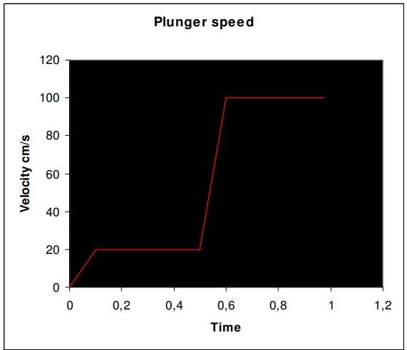
- 일반적인 프로파일: 플런저가 일정한 저속으로 움직이다가 급격히 가속하는 방식 (Figure 1).
- 최적화된 프로파일: 플런저가 두 번의 일정하고 제어된 가속으로 움직이는 방식 (Figure 7).
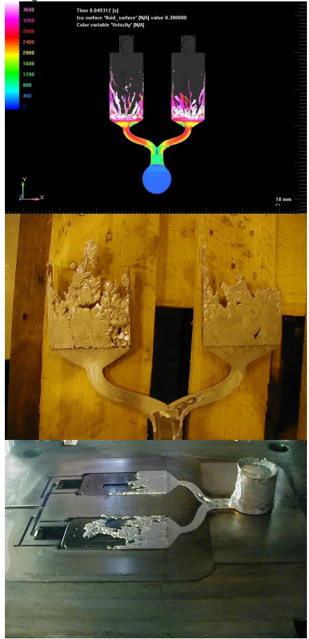
결과로 나타나는 파형과 금속에 혼합된 공기의 체적 분율을 시각화함으로써, 각 접근법의 효과를 직접 정량화할 수 있었습니다. 시뮬레이션 결과는 실제 숏 샷(short shot) 실험으로 검증되었습니다(Figure 9).
핵심 성과: 주요 연구 결과 및 데이터
시뮬레이션 결과는 플런저 제어가 품질에 어떻게 직접적인 영향을 미치는지 명확하고 시각적으로 보여줍니다.
- 결과 1: 최적화되지 않은 플런저 프로파일은 공기 포켓을 생성: 일정한 속도 후 급가속하는 일반적인 프로파일은 얕은 초기 파동을 생성했습니다. 두 번째 고가속 단계는 강한 스플래싱 파동을 일으켜 첫 번째 파동 위로 부서졌습니다. Figure 3과 Figure 4에서 명확히 볼 수 있듯이, 이 충돌은 용탕이 다이 캐비티에 들어가기 전에 "상당한 양의 공기"를 내부에 가둡니다. Figures 5와 6은 슬리브 내부에 형성된 이 큰 공기 방울을 보여줍니다.
- 결과 2: 최적화된 가속은 안정적인 파면을 생성: 두 번의 일정한 가속을 사용한 프로파일은 훨씬 다른 결과를 낳았습니다. 각 가속에 의해 형성된 파면은 함께 유지되어 슬리브를 따라 부드럽게 전진하는 단일하고 결합된 파면을 형성했습니다. Figure 7에서 볼 수 있듯이, 이 안정적인 파동은 실린더 헤드에 깨끗하게 도달하여 "최소한의 공기 혼입"을 유발합니다(Figure 8).
- 결과 3: 샷 슬리브 시뮬레이션은 정확한 캐비티 충진 분석의 전제 조건: 본 연구는 샷 슬리브에서 생성된 조건이 공정의 나머지 부분에 대한 중요한 시작점임을 입증했습니다. 논문은 캐비티 분석에 사용되는 데이터의 신뢰성과 정확성을 보장하기 위해 "캐비티 충진 시뮬레이션 전에 샷 슬리브 공정을 시뮬레이션하는 것이 필수적"이라고 결론 내렸습니다(Figure 9). 저자들은 플런저 움직임의 최적화는 "시뮬레이션 없이는 불가능하다"고 말합니다.
HPDC 제품에 대한 실질적인 시사점
- 공정 엔지니어를 위한 시사점: 이 연구 결과는 명확한 지침을 제공합니다: 플런저 속도 프로파일은 추측이 아닌 공학적으로 설계되어야 합니다. 이 연구는 Figure 7에서 볼 수 있듯이 최적화된 다단계 가속 프로파일을 시뮬레이션하고 구현함으로써 공정의 가장 첫 단계에서 공기 혼입을 사전에 최소화할 수 있음을 시사합니다. 이는 논문의 결론에서 언급된 바와 같이 HPDC 기계의 보다 정밀한 제어와 준비 시간 단축을 가능하게 합니다.
- 품질 관리를 위한 시사점: 플런저 프로파일(Figure 1 vs. Figure 7)과 그에 따른 공기 혼입(Figure 5 vs. Figure 8) 사이의 직접적인 시각적 상관관계는 사전 품질 보증을 위한 강력한 도구를 제공합니다. 단순히 가스 기공을 검사하는 대신, 팀은 기계 파라미터가 기공 형성을 애초에 방지하도록 설정되었는지 확인할 수 있습니다.
- 금형 설계를 위한 시사점: 이 연구는 전체 시스템이 상호 연결되어 있음을 강조합니다. 결론에서는 "게이트 및 벤트의 설계와 위치를 포함한 캐비티 형상이 매우 중요하다"고 명시합니다. 최적화된 샷 슬리브 공정을 통해 생성된 깨끗하고 공기가 없는 용탕 흐름은 후속 게이트 및 캐비티 충진이 설계대로 수행되도록 보장하여 추가적인 결함을 방지합니다.
논문 상세 정보
Complete Simulation of High Pressure Die Casting Process
1. 개요:
- Title: Complete Simulation of High Pressure Die Casting Process
- Author: Matti Sirviö, Sami Vapalahti, Jukka Väinölä (VTT Industrial Systems, Conrod Team)
- Year of publication: 문서에 명시되지 않음 (참고 문헌을 기반으로 1999년경으로 추정).
- Journal/academic society of publication: 명시되지 않음; 학회 발표 자료(예: NADCA)일 가능성이 높음.
- Keywords: High Pressure Die Casting (HPDC), Simulation, Shot Sleeve, Fluid Flow, Air Entrapment, Porosity, Plunger Speed.
2. Abstract (초록):
The use of simulation programs saves time and reduces the costs of the casting system design. At the same time it is possible to meet stringent product quality. Simulation can make a casting system optimal: it enables the producing of sound, high-quality castings with fewer experiments. Furthermore environmental savings and economical use of materials can be achieved when the number of test castings is reduced. Foundries use now widely simulation codes that are based on a thermal conduction model where thermal conduction in the melt and liberation of latent heat during solidification are considered. Fluid flow simulations are less used. However, e.g. aluminium die casting is so complicated in which flow momentum plays a crucial role in the mould filling process due to the high velocity of the liquid metal. Inertia effects may cause splashing, jetting or undesirable filling of the metal flow into mould cavity. When considering complex parts, the accurate prediction of mould filling behaviour using empirical knowledge is nearly impossible. In most of the industrial nations, about 70% of the diecast parts go to the automotive industry. Aluminium diecastings are gaining importance in the production of lightweight vehicle bodies, as for example used in new model Audi cars. Therefore, it is even more vital today that these castings can be produced with the high quality methods. In this context the simulation is becoming more essential in the designing process. This paper describes the advantages of the Shot Sleeve simulations to attain better casting system design in HPDC castings. Filling analysis is used to determine the size and location of the gate as well as proper runner system design for ensuring a complete and balanced filling of the part. Shot sleeve simulations in High Pressure Die Casting process ensures the minimum air entrapment during the pre-filling phase.
3. Introduction (서론):
Computer simulations of various kinds are gradually becoming widely recognised tools in numerous design processes. Simulation codes are widely used in the foundry industry. Computer simulation of the casting process began with solidification modelling. For this reason, the codes are used, in most cases, for heat transfer calculations in order to predict hot spots and to avoid porosity in castings¹. Fluid flow simulations are less widely used. One of the reasons is that only a few of the codes can adequately simulate highly dynamic flows. On the other hand, all of the known methods require a significant degree of human effort during the pre-processing phase of the simulation process. This excludes the everyday practical use of such methods, when complicated geometries are utilised: The enmeshing process takes simply too long and often calculation meshes must be fixed in order to achieve converged solutions. Furthermore, although the casting geometry has been received from the workshop, adding the channels may involve considerable effort. For these reasons, many foundries tend to trust to their empirical knowledge². However, fluid flow simulations should be used in many instances, e.g. in aluminium die casting, which is particularly because flow momentum plays a crucial role in the mould filling process due the high velocity of the liquid metal. Inertia effects may cause splashing, jetting or undesirable filling of the metal flow into mould cavity. When considering complex parts, the accurate prediction of mould filling behaviour using only empirical knowledge is virtually impossible³. It is commonly accepted that shrinkage and gas are two major causes of porosity. The shrinkage porosity is associated with the hot spot in the casting. The gas porosity has four different reasons: 1) Trapped air that is entrained in the injection system and cavity: 2) Gas generated from burned lubricants; 3) Gas generated from water that may be in cavity and 4) Hydrogen gas. The gas porosity due to the trapped air is an unwanted byproduct of relatively high velocity injection method used. Gas entrapment is caused by turbulent flow pattern generated during metal injection process. The location, size and total volume of contained gas porosity are influenced by the method chosen to fill cavity with molten alloy. In high pressure die casting, some efforts have been made to reduce air entrapment by the modification of conventional injection shot profile taking advantages of the development of advanced and reliable control systems.
4. 연구 요약:
연구 주제 배경:
고압 다이캐스팅은 특히 자동차 산업에서 지배적인 제조 공정입니다. 그러나 고속 사출 공정 중 용탕에 공기가 혼입되어 발생하는 가스 기공과 같은 품질 문제에 취약합니다.
이전 연구 현황:
주조 산업의 대부분 시뮬레이션 연구는 열점(hot spot) 예측을 위한 열 및 응고 모델링에 집중되었습니다. 유동 시뮬레이션은 그 복잡성 때문에 덜 보편적으로 사용되었습니다. 그 결과, 플런저 사출 프로파일과 같은 핵심 공정 파라미터는 일반적으로 비효율적인 시행착오를 통해 결정되었습니다.
연구 목적:
샷 슬리브 예비 충진 단계를 시뮬레이션하는 것이 최적의 HPDC 공정을 설계하는 데 필수적임을 입증하는 것입니다. 본 연구는 시뮬레이션을 통해 플런저의 움직임을 최적화하는 것이 어떻게 직접적으로 공기 혼입을 최소화하고 결과적으로 최종 주물 품질을 향상시킬 수 있는지를 보여주는 것을 목표로 했습니다.
핵심 연구 내용:
본 연구는 유동 시뮬레이션을 이용한 비교 연구를 수행했습니다. 단일 급가속을 포함하는 일반적인 프로파일과 두 번의 일정한 가속을 갖는 최적화된 프로파일, 이렇게 두 가지 다른 플런저 속도 프로파일을 모델링했습니다. 각 프로파일에 대한 용탕의 파형, 속도 및 혼입된 공기의 양을 분석했습니다.
5. 연구 방법론
연구 설계:
본 연구는 콜드 챔버 HPDC 샷 슬리브 내에서 두 가지 다른 플런저 이동 프로파일을 시뮬레이션하는 비교 연구 설계를 사용했습니다. 목표는 각 시나리오에서 발생하는 유체 역학을 비교하고 공기 혼입량을 정량화하는 것이었습니다.
데이터 수집 및 분석 방법:
데이터는 완전한 나비에-스토크스 방정식을 풀고 자유 표면 유동을 모델링할 수 있는 유동 시뮬레이션 프로그램(Flow-3D로 명시됨)을 사용하여 생성되었습니다. 이를 통해 용탕 속도, 파형, 공기와 금속의 체적 분율에 대한 상세한 시각화가 가능했습니다. 시뮬레이션 결과는 실제 숏 샷 실험을 통해 검증되었습니다.
연구 주제 및 범위:
본 연구는 콜드 챔버 다이캐스팅 공정의 예비 충진 단계에 구체적으로 초점을 맞췄습니다. 그 범위는 샷 슬리브 내의 유체 역학과 플런저 속도 및 가속 프로파일이 파형 및 공기 혼입에 미치는 직접적인 영향에 국한되었습니다.
6. 주요 결과:
주요 결과:
- 일반적인 플런저 프로파일(일정한 속도 후 고가속)은 두 개의 뚜렷한 파동을 만들어 충돌시키고, 용탕 내에 큰 공기 방울을 가둡니다 (Figures 1-6).
- 두 번의 일정한 가속을 사용하는 최적화된 플런저 프로파일은 단일하고 안정적인 결합 파면을 생성하여 최소한의 공기 혼입으로 슬리브를 부드럽게 채웁니다 (Figures 7-8).
- 논문은 플런저 움직임의 최적화는 "시뮬레이션 없이는 불가능하다"고 결론 내리며, 신뢰할 수 있는 데이터를 얻기 위해 캐비티 충진 시뮬레이션 전에 샷 슬리브 시뮬레이션을 수행하는 것이 "필수적"이라고 말합니다 (Figure 9, Conclusion).
Figure 이름 목록:
- Fig. 1. Slow shot profile, that has two plunger accelerations.
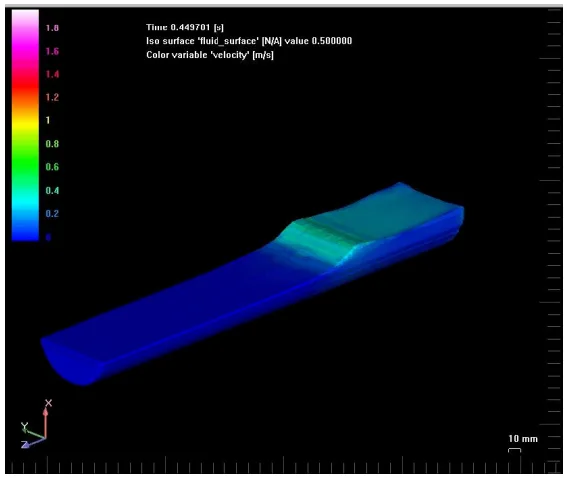
- Fig.2. First acceleration cause shallow wave. (Colour scale:Meters per second).
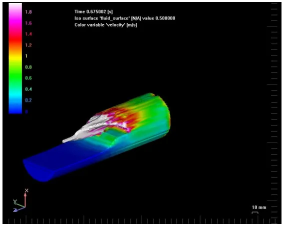
- Fig.3. Second acceleration causes splashing wave which is crushing shallow wave.
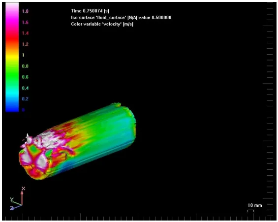
- Fig.4. When these two waves collide, a large air entrapment is formed inside the waves.
- Fig.5 and 6.. Volume fraction picture illustrates air entrapment and how the air mixes with the metal. In these pictures, it can be seen how the two waves form an air bubble inside the sleeve. (Colour scale - volume fraction: White is 100% metal and blue is 100 % air)
- Fig. 7. The plunger is moved using two constant accelerations. The two waves form a combined wave front which hits the cylinder head. Minimal air entrapment occurs. (Colour scale: Meters per second).
- Fig. 8. The two waves form a combined wave front which hits the cylinder head. Minimal air entrapment occurs.
- Fig.9. Short shot experiments proved that it is vital to simulate shot sleeve process before cavity filling simulations.
7. Conclusion (결론):
Shot sleeve simulations give valuable information to the manufacturer what will be the final quality of the product. If the HPDC machines could be controlled according to these simulation results, it would mean substantial savings in lead times, production planning and high decrease in scrap production. Along with cavity pre-fill percentage and transition time, cavity geometry including the design and locations of gates and vents was found to be very important parameter to be considered to achieve optimal cavity fill in terms of air entrapment. The shot sleeve process is quite difficult process to simulate and the efficient usage of results require the possibility to control HPDC machines. Following direct improvements could be gained:
- Improvement of the casting quality by minimising the entrapped air during the shot sleeve process
- Minimising set up time during the start of casting process
- Possibility to control HPDC machines more precisely
- Optimisation of the whole casting process by controlling filling with optimal plunger movement
- Shorter lead time during the tool designing process
- Less scrap and waste production when new design is taken on the use.
Simulations demonstrated the importance of calculating the filling of the casting in Aluminium Casting process. With certain castings, there are situations where the channel design can prevent the proper filling of the casting. These situations are very difficult to predict without simulations. Shot Sleeve simulations proved that it is extremely important to simulate the process with actual plunger movements. The optimisation of plunger movement is impossible to achieve without simulation. It is important that the simulation program employed is able to model the free surfaces of the flow correctly in order to predict air entrapment.⁵
8. References (참고 문헌):
- [1] Sirviö, M. and Martikainen, H. “Simultaneous engineering between workshops and foundries”. Int. Conf. on Best Practices in the Production, Processing and Thermal Treatment of Castings. Singapore, 10 - 12 Oct. 1995. Paper 17-1-6
- [2] Sirviö, M. and Louvo, A. “Use of simulated porosity for avoidance of casting defects”. International GIFA Congress Metal Casting '94 (GIFA '94). Dusseldorf, 15 - 18 June 1994. German Foundrymen's Association (1994), 8 p.
- [3] Thorpe, W., Ahuja,V., Jahedi, M., Cleary,P. and Stokes, N,. “Simulation of Fluid Flow Within the Die Cavity in High Pressure Die Casting Using Smooth Particle Hydrodynamics”. Trans 20th Int Die Casting Cong & Expo, NADCA, Cleveland, 1999, T99-014.
- [4] Brevick, Jerald R., Professor, “Computer Flow Modeling of Cavity Pre-fill Effectsin High Pressure Die Casting”. Trans 20th Int Die Casting Cong & Expo, NADCA, Cleveland, 1999, T99-011.
- [5] Sirviö, M. “Computer integrated patternless casting process for SMEs (Project BE - 1969)”. EUR 18160. Proceedings of the Conference on Industrial Technologies. Toulouse, 27 - 30 Oct. 1997. European Commission. Luxembourg (1998), 116
- [6] Venkatsen and Shivipouri, “Numerical investigation of the effect of gate size of die casting parts”. Trans 18th Int Die Casting Cong & Expo, NADCA, Indianapolis, pp.66-74.
전문가 Q&A: 가장 중요한 질문에 대한 답변
Q1: 대부분 캐비티 충진에 집중하는데, 샷 슬리브 시뮬레이션이 왜 그렇게 중요한가요?
A1: 이 논문은 용탕의 초기 조건이 샷 슬리브에서 결정된다는 것을 증명합니다. 부적절한 플런저 움직임은 Figures 4, 5, 6에서 보여주듯이 금속이 게이트에 도달하기도 전에 "상당한 양의 공기"를 혼입시킬 수 있습니다. 논문은 전체 공정에 대한 신뢰할 수 있는 데이터를 얻기 위해 "캐비티 충진 시뮬레이션 전에 샷 슬리브 공정을 시뮬레이션하는 것이 필수적"이라고 말합니다 (결론, Figure 9).
Q2: 연구에서 공기 혼입을 줄이는 데 가장 효과적이라고 밝혀진 구체적인 플런저 이동 프로파일은 무엇인가요?
A2: 이 연구는 두 번의 일정한 가속을 사용하는 프로파일이 훨씬 우수하다는 것을 발견했습니다. 이는 Figures 7과 8에서 설명된 바와 같이 "최소한의 공기 혼입"으로 슬리브를 따라 부드럽게 이동하는 단일하고 결합된 파면을 생성합니다. 이는 파동이 충돌하여 공기를 가두는 일반적인 프로파일과 극명한 대조를 이룹니다.
Q3: 공기 혼입을 피하기 위해 플런저 속도를 느리게만 하는 것으로 충분한가요?
A3: 아니요. 논문은 속도가 너무 낮으면 "결과 파동이 챔버 단면을 제대로 채울 만큼 충분히 높지 않을 것"이라고 명확히 합니다. 반대로 너무 높은 속도는 "공기를 가두는 서징 파동(surging wave)을 유발합니다." 핵심은 단지 속도가 아니라 안정적인 뱅크업(banked-up) 파동을 만들기 위한 최적의 가속 프로파일입니다 (샷 슬리브 시뮬레이션 섹션).
Q4: 품질 향상 외에 이 시뮬레이션 접근법을 도입함으로써 얻을 수 있는 비즈니스 이점은 무엇인가요?
A4: 결론 섹션에서는 "리드 타임의 상당한 절감", "스크랩 생산의 대폭 감소", "준비 시간 최소화", "금형 설계 시 리드 타임 단축" 등 여러 직접적인 비즈니스 이점을 나열합니다. 이는 금속을 주조하기 전에 공정 최적화를 가능하게 하여 시간과 재료를 절약합니다.
Q5: 이러한 최적화가 경험적 지식이나 시행착오로 가능한가요?
A5: 논문은 복잡한 부품의 경우 사실상 불가능하다고 주장합니다. "플런저 움직임의 최적화는 시뮬레이션 없이는 불가능하다"고 명시합니다 (결론). 또한, "경험적 지식만으로 충진 거동을 예측하는 것은 사실상 불가능하다"고 합니다 (서론).
결론 및 다음 단계
이 연구는 HPDC에서 부품 품질을 향상시키기 위한 귀중한 로드맵을 제공합니다. 종종 간과되었던 샷 슬리브 단계에 초점을 맞춤으로써, 이 연구 결과는 공기 혼입을 최소화하고, 기공 결함을 줄이며, 가장 첫 단계부터 생산을 최적화하기 위한 명확하고 데이터 기반의 경로를 제공합니다.
CASTMAN은 고객의 가장 까다로운 다이캐스팅 문제를 해결하기 위해 최신 산업 연구를 적용하는 데 전념하고 있습니다. 이 백서에서 논의된 문제가 귀사의 운영 목표와 관련이 있다면, 당사 엔지니어링 팀에 연락하여 이러한 고급 원칙을 귀사의 부품에 적용하는 방법을 논의하십시오.
저작권
- 이 자료는 "Matti Sirviö, Sami Vapalahti, Jukka Väinölä"의 논문 "Complete Simulation of High Pressure Die Casting Process"를 기반으로 합니다.
- 논문 출처: 원본 문서의 발행 세부 정보에 따라 VTT Industrial Systems.
이 자료는 정보 제공 목적으로만 사용됩니다. 무단 상업적 사용은 금지됩니다. Copyright © 2025 CASTMAN. All rights reserved.