본 논문 요약은 [IEEE TRANSACTIONS ON COMPONENTS AND PACKAGING TECHNOLOGY]에 발표된 논문 "[Comparison of Micro-Pin-Fin and Microchannel Heat Sinks Considering Thermal-Hydraulic Performance and Manufacturability]"를 기반으로 작성되었습니다.
1. 개요:
- 제목: 열-유압 성능 및 제조 가능성을 고려한 마이크로 핀-핀 및 마이크로 채널 방열판 비교 (Comparison of Micro-Pin-Fin and Microchannel Heat Sinks Considering Thermal-Hydraulic Performance and Manufacturability)
- 저자: Benjamin A. Jasperson, Yongho Jeon, Kevin T. Turner, Frank E. Pfefferkorn, and Weilin Qu
- 발행 연도: 2010년 3월
- 발행 학술지/학회: IEEE TRANSACTIONS ON COMPONENTS AND PACKAGING TECHNOLOGY
- 키워드: 마이크로 방열판, 마이크로 제조, 마이크로 가공, 핀-핀 방열판 (Micro heat sink, micro-manufacturing, micro-machining, pin-fin heat sink)
2. 연구 배경:
- 연구 주제의 사회적/학문적 맥락:
- 마이크로 전자 장치의 발열량이 증가함에 따라 작은 면적에서 높은 열 유속을 소산시킬 수 있는 고효율 열 관리 기술에 대한 요구가 증가하고 있습니다.
- 내부 열 전달 향상 구조를 가진 단상 액체 냉각 방식의 초소형 방열판이 해결책으로 떠올랐습니다. 평행판 핀이 널리 연구되었습니다.
- 최근 마이크로 제작 기술의 발전으로 인해 더욱 복잡한 3차원 향상 구조, 예를 들어 엇갈린 마이크로 핀-핀 배열과 같은 구조를 제작할 수 있게 되었습니다.
- 기존 연구의 한계:
- 마이크로 채널 방열판은 열-유압 성능 모델이 잘 확립되어 있지만, 마이크로 핀-핀 방열판의 신뢰할 수 있는 모델은 복잡한 유동 및 열 전달 특성으로 인해 부족합니다. 기존 연구는 대부분 경험적 연구에 기반하고 있습니다.
- 마이크로 핀-핀 방열판이 마이크로 채널 방열판에 비해 실용적인 선택이 되기 위해서는 경제성과 현실적인 마이크로 제작 옵션이 중요합니다.
- 연구의 필요성:
- 마이크로 핀-핀 방열판과 마이크로 채널 방열판의 열-유압 성능을 비교하기 위해.
- 금속으로 만들어진 마이크로 방열판 제작에 적합한 제조 방법을 평가하기 위해.
- 마이크로 엔드 밀링을 사용하여 마이크로 핀-핀 및 마이크로 채널 방열판 설계 간의 제조 비용 차이를 파악하기 위해.
- 열 성능, 유압 성능 및 제조 비용을 종합적으로 비교하기 위해.
3. 연구 목적 및 연구 질문:
- 연구 목적:
- 높은 열 유속을 소산시키는 대안으로서 마이크로 핀-핀 및 마이크로 채널 방열판의 열-유압 성능과 제조 가능성을 동시에 비교하는 것.
- 주요 연구 질문:
- 마이크로 핀-핀 설계가 열-유압 성능 측면에서 마이크로 채널 설계를 능가하는가?
- 금속으로 마이크로 방열판을 제작하는 데 적합한 제조 방법은 무엇인가?
- 마이크로 엔드 밀링을 사용할 때 마이크로 핀-핀과 마이크로 채널 방열판 설계 간의 제조 비용 차이는 무엇인가?
- 연구 가설:
- 마이크로 핀-핀 방열판은 마이크로 채널 방열판에 비해 향상된 열 전달 성능을 가질 가능성이 있지만, 압력 강하 및 제조 비용 측면에서 상충 관계가 있을 것이다.
- 마이크로 엔드 밀링을 사용할 때 가공 시간은 두 설계 간의 제조 비용 차이를 결정하는 주요 요인이다.
4. 연구 방법론
- 연구 설계:
- 마이크로 핀-핀 및 마이크로 채널 방열판의 열-유압 성능에 대한 비교 실험 연구.
- 제조 비용을 비교하기 위한 마이크로 엔드 밀링 사례 연구.
- 마이크로 방열판을 위한 다양한 제조 기술 검토.
- 자료 수집 방법:
- 단상 수냉각을 사용하여 두 방열판 설계의 열 저항 및 압력 강하에 대한 실험적 측정.
- 기존 문헌을 기반으로 한 마이크로 채널 방열판 성능에 대한 분석 모델.
- 공구 경로 길이 및 제조 매개변수를 기반으로 한 가공 시간 및 비용 분석.
- 분석 방법:
- 다양한 유량에 따른 두 설계의 실험적 열 저항 및 압력 강하 데이터 비교.
- 공구 경로 길이 및 제조 매개변수를 기반으로 가공 시간 및 비용 계산.
- 대량 생산 적합성, 시제품 제작 적합성 및 비용을 기준으로 한 다양한 제조 방법에 대한 질적 평가.
- 연구 대상 및 범위:
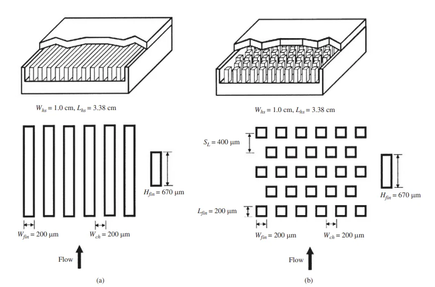
- 채널/핀 폭 200 µm, 높이 670 µm의 구리 (110) 마이크로 방열판.
- 마이크로 핀-핀 방열판: 1950개의 마이크로 핀이 엇갈린 배열.
- 마이크로 채널 방열판: 평행 채널.
- 냉각수: 단상 물.
- 제조 방법 초점: 마이크로 엔드 밀링.
5. 주요 연구 결과:
- 주요 연구 결과:
- 열 성능: 마이크로 핀-핀 방열판은 약 60g/min 이상의 액체 유량에서 마이크로 채널 방열판에 비해 낮은 대류 열 저항을 나타냅니다. 60g/min 미만에서는 마이크로 채널 방열판이 더 낮은 열 저항을 보입니다. (그림 10. 마이크로 핀-핀 방열판과 마이크로 채널 방열판의 평균 대류 열 저항 비교 참조).
- 유압 성능: 마이크로 핀-핀 방열판은 테스트한 모든 유량 범위에서 마이크로 채널 방열판보다 현저히 높은 압력 강하를 나타냅니다. (그림 11. 마이크로 핀-핀 방열판과 마이크로 채널 방열판의 압력 강하 비교 참조).
- 제조 비용: 마이크로 핀-핀 방열판은 마이크로 엔드 밀링을 사용하여 제조하는 데 마이크로 채널 방열판보다 약 3배 더 비싸며, 이는 주로 더 복잡한 핀-핀 형상에 필요한 더 긴 가공 시간 때문입니다. 가공 시간이 주요 비용 요인입니다. (그림 14. 1cm x 3.38cm 면적에 대한 핀/벽 폭의 함수로서의 총 가공 거리 (공구 경로) 참조).
- 통계적/질적 분석 결과:
- 마이크로 채널 방열판에 대한 분석 모델은 예상되는 추세와 잘 일치합니다.
- 제조 기술 검토 (표 I. 마이크로 방열판의 잠재적 제조 방법)는 마이크로 EDM, 마이크로 레이저 가공 및 마이크로 주조가 대량 생산에 적합함을 나타냅니다.
- 데이터 해석:
- 고유량에서 마이크로 핀-핀 방열판의 향상된 열 성능은 더 구불구불한 유동과 더 강한 와류로 인해 열 전달이 향상된 것으로 해석됩니다.
- 마이크로 핀-핀 설계에서 더 높은 압력 강하는 핀 배열로 인한 항력 증가 때문입니다.
- 가공 시간 차이는 공구 경로의 복잡성과 직접적으로 연결되며, 이는 엇갈린 핀-핀 형상에서 훨씬 더 깁니다.
- Figure Name List:
- Fig. 1. Structure and dimension of (a) microchannel heat sink and (b) micro-pin-fin heat sink.
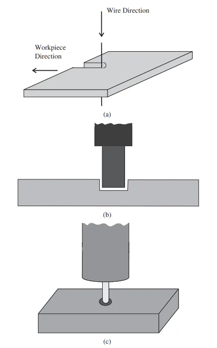
- Fig. 2. Illustrations of three electrodischarge machining techniques: (a) wire EDM, (b) die sinking, and (c) EDM milling.
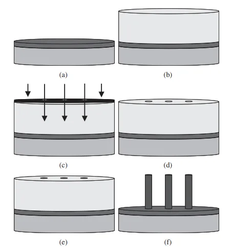
- Fig. 3. Schematic of LIGA process.
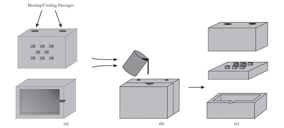
- Fig. 4. Schematic of die casting.
- Fig. 5. Schematic of extrusion process.
- Fig. 6. Schematic of micro powder injection molding.
- Fig. 7. Schematics of milling: (a) slot milling and (b) end milling.
- Fig. 8. Schematic of chip load.
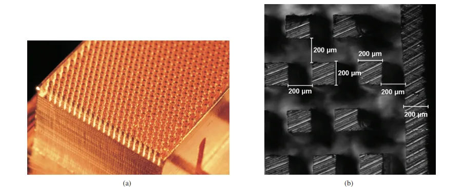
- Fig. 9. Photographs of (a) copper heat sink and (b) pin fin geometry created by micro-end-milling.
- Fig. 10. Comparison of micro-pin-fin heat sink and microchannel heat sink average convection thermal resistance for (a) Tin = 30 °C and (b) Tin = 60 °C.
- Fig. 11. Comparison of micro-pin-fin heat sink and microchannel heat sink pressure drop for (a) Tin = 30 °C and (b) Tin = 60 °C.
- Fig. 12. Illustration of tool path for milling channel heat sink.
- Fig. 13. Illustration of tool path for milling staggered pin heat sink.
- Fig. 14. Total machining distance (tool path as a function of pin/wall width for a 1 cm x 3.38 cm area).
2. Research Background:
6. 결론 및 논의:
- 주요 결과 요약:
- 마이크로 핀-핀 방열판은 고유량 (>60g/min)에서 더 나은 열 성능을 제공하지만, 마이크로 채널 방열판에 비해 압력 강하 및 제조 비용이 증가합니다.
- 마이크로 핀-핀 방열판의 마이크로 엔드 밀링 비용은 더 긴 가공 시간으로 인해 약 3배 더 높습니다.
- 연구의 학문적 의의:
- 마이크로 핀-핀 및 마이크로 채널 방열판의 열-유압 성능 및 제조 가능성에 대한 직접적인 비교를 제공합니다.
- 마이크로 핀-핀 배열에서의 유동 거동 및 열 전달 메커니즘에 대한 통찰력을 제공합니다.
- 마이크로 엔드 밀링을 사용한 방열판의 마이크로 제조 비용 요인에 대한 이해에 기여합니다.
- 실용적 의미:
- 열 성능, 압력 강하 및 비용 간의 상충 관계를 고려하여 응용 분야 요구 사항에 따라 방열판 설계를 선택하는 데 지침을 제공합니다.
- 마이크로 제조 비용에서 가공 시간의 중요성과 공정 개선 (예: 더 높은 스핀들 속도, 고급 공구 코팅)을 통한 비용 절감 가능성을 강조합니다.
- 마이크로 핀-핀 방열판의 대량 생산을 위한 잠재적인 비용 효율적인 방법으로 주조를 제안하여 마이크로 채널 설계와 비교했을 때 비용 차이를 최소화합니다.
- 연구의 한계:
- 비용 분석은 마이크로 엔드 밀링에 국한되며 다른 제조 방법에서는 다를 수 있습니다.
- 비용 비교를 위해 일정한 이송 속도와 공구 수명을 가정하지만, 실제 시나리오에서는 완전히 정확하지 않을 수 있습니다.
- 특정 형상에 초점을 맞추고 있으며 모든 마이크로 핀-핀 및 마이크로 채널 설계에 일반화할 수 없을 수 있습니다.
7. 향후 후속 연구:
- 후속 연구 방향:
- 열 성능 및 압력 강하를 최적화하기 위해 다른 핀 핀 설계 (다이아몬드, 원형, 에어포일)를 탐색합니다.
- 생산성 향상 (더 높은 이송 속도, 스핀들 속도, 고급 공구 코팅)이 제조 비용 및 설계 간 비용 차이 감소에 미치는 영향을 조사합니다.
- 마이크로 핀-핀 방열판의 단위 비용을 줄이기 위해 주조 및 기타 대량 생산 방법에 대한 추가 연구를 진행합니다.
- 추가 탐구가 필요한 영역:
- 특정 응용 분야 및 유동 조건에 대한 마이크로 핀-핀 형상 최적화.
- 마이크로 핀-핀 방열판의 열-유압 성능을 예측하기 위한 더 정확하고 포괄적인 모델 개발.
- 다양한 제조 방법 및 생산량을 고려한 상세한 비용 분석.
8. 참고 문헌:
- [1] T. M. Harms, M. J. Kazmierczak, and F. M. Gerner, "Developing convective heat transfer in deep rectangular microchannels," Int. J. Heat Fluid Flow, vol. 20, no. 2, pp. 149-157, 1999.
- [2] K. Kawano, K. Minakami, H. Iwasaki, and M. Ishizuka, "Microchannel heat exchanger for cooling electrical equipment," presented at Proc. ASME Int. Mech. Eng. Congr. Expo., Fairfield, NJ, 1998.
- [3] P.-S. Lee, S. V. Garimella, and D. Liu, "Investigation of heat transfer in rectangular microchannels," Int. J. Heat Mass Transfer, vol. 48, no. 9, pp. 1688-1704, 2005.
- [4] W. Qu and I. Mudawar, "Experimental and numerical study of pressure drop and heat transfer in a single-phase microchannel heat sink," Int. J. Heat Mass Transfer, vol. 45, no. 12, pp. 2549-2565, Jun. 2002.
- [5] D. B. Tuckerman and R. F. W. Pease, "High-performance heat sinking for VLSI," IEEE Electron. Devices Lett., vol. 2, no. 5, pp. 126-129, May 1981.
- [6] A. Kosar, C.-J. Kuo, and Y. Peles, "Hydoroil-based micro-pin-fin heat sink," in Proc. 2006 ASME Int. Mech. Eng. Congr. Expo., (IMECE'06) Microelectromech. Syst., Chicago, pp. 563-570.
- [7] A. Kosar, C. Mishra, and Y. Peles, "Laminar flow across a bank of low aspect ratio micro-pin-fins," J. Fluids Eng., Trans. ASME, vol. 127, no. 3, pp. 419-430, 2005.
- [8] A. Kosar and Y. Peles, "Thermal-hydraulic performance of MEMS-based pin fin heat sink," J. Heat Transfer, vol. 128, no. 2, pp. 121-131, 2006.
- [9] Y. Peles and A. Kosar, "Convective flow of refrigerant (R-123) across a bank of micro-pin-fins," Int. J. Heat Mass Transfer, vol. 49, no. 17-18, pp. 3142-3155, 2006.
- [10] Y. Peles, A. Kosar, C. Mishra, C.-J. Kuo, and B. Schneider, "Forced convective heat transfer across a pin fin micro heat sink," Int. J. Heat Mass Transfer, vol. 48, no. 17, pp. 3615-3627, 2005.
- [11] R. S. Prasher, "Nusselt number and friction factor of staggered arrays of low aspect ratio micro-pin-fins under cross flow for water as fluid," J. Heat Transfer, vol. 129, no. 2, pp. 141-153, 2007.
- [12] A. Siu-Ho, W. Qu, and F. Pfefferkorn, "Experimental study of pressure drop and heat transfer in a single-phase micro-pin-fin heat sink," Trans. ASME. J. Electron. Packaging, vol. 129, no. 4, pp. 479-487, 2007.
- [13] W. Qu and A. Siu Ho, "Liquid single-phase flow in an array of micro-pin-fins. Part I. Heat transfer characteristics," J. Heat Transfer, vol. 130, no. 12, pp. 122402-1-122402-11, Dec. 2008.
- [14] W. Qu and A. Siu Ho, "Liquid single-phase flow in an array of micro-pin-fins. Part II: Pressure drop characteristics," J. Heat Transfer, vol. 130, no. 12, pp. 124501-1-124501-4, 2008.
- [15] J. Eugene, F. Xi, B. Tan, and B. A. Jubran, "An overview on micro-meso manufacturing techniques for micro heat exchangers for turbine blade cooling," Int. J. Manufacturing Res., vol. 3, no. 1, pp. 3-26, 2008.
- [16] K. H. Ho and S. T. Newman, "State of the art electrical discharge machining (EDM)," Int. J. Mach. Tools Manufacture, vol. 43, no. 13, pp. 1287-1300, 2003.
- [17] S. Kalpakjian and S. R. Schmid, “Advanced manufacturing processes," in Manufacturing Engineering and Technology, 5th ed. Upper Saddle River, NJ: Pearson Education, Inc., 2006, ch. 27, pp. 846-850.
- [18] C. S. Lin, Y. S. Liao, and S. T. Chen, "Development of a novel micro wire-EDM mechanism for the fabricating of micro parts," presented at Int. Conf. Advanced Manufacture, Taipei, Taiwan, 2005.
- [19] X. Cheng, "Development of ultraprecision machining system with unique wire EDM tool fabrication system for micro/nano-machining," CIRP Ann. Manufacturing Technol., vol. 57, no. 1, pp. 415-420, 2008.
- [20] D. T. Pham, S. S. Dimov, S. Bigot, A. Ivanov, and K. Popov, "Micro-EDM recent developments and research issues," presented at 14th Int. Symp. Electromach., Edinburgh, Scotland, 2004.
- [21] A. B. M. A. Asad, T. Masaki, M. Rahman, H. S. Lim, and Y. S. Wong, "Tool-based micro-machining," J. Materials Process. Tech., vol. 192-193, pp. 204-211, 2007.
- [22] M. M. Sundaram, S. Billa, and K. P. Rajurkar, "Generation of high aspect ratio micro holes by a hybrid micromachining process," presented at ASME Int. Conf. Manufacturing Sci. Eng., Atlanta, GA, 2007.
- [23] W. Ehrfeld, "Micro electro discharge machining as a technology in micromachining," in Proc. SPIE Int. Soc. Optical Eng., vol. 2879. Austin, TX, 1996, pp. 332-337.
- [24] M. Sundaram and K. Rajurkar, "Toward freeform machining by micro electro discharge machining process," Trans. North Amer. Manufacturing Res. Inst., vol. 36, pp. 381-388, 2008.
- [25] J. S. Coursey, J. Kim, and K. T. Kiger, "Spray cooling of high aspect ratio open microchannels,” J. Heat Transfer, vol. 129, no. 8, pp. 1052-1059, 2007.
- [26] M. J. Madou, "Lithography," in Fundamentals of Microfabrication, 2nd ed. Boca Raton, FL: CRC Press, 2002, ch. 1, pp. 1-10, 49-50.
- [27] R. Muwanga and I. Hassan, "Flow boiling oscillations in microchannel heat sinks," presented at 9th AIAA/ASME Joint Thermophysics Heat Transfer Conf., San Francisco, CA, 2006.
- [28] S. Stefanescu, M. Mehregany, J. Leland, and K. Yerkes, "Micro jet array heat sink for power electronics," presented at Proc. IEEE Micro Electro Mechn. Syst., Orlando, FL, 1999.
- [29] X. Wei, C. H. Lee, Z. Jiang, and K. Jiang, "Thick photoresists for electroforming metallic microcomponents," J. Mech. Eng. Sci., vol. 222, no. 1, pp. 37-42, 2008.
- [30] C. H. Ho, K. P. Chin, C. R. Yang, H. M. Wu, and S. L. Chen, "Ultrathick SU-8 mold formation and removal, and its application to the fabrication of LIGA-like micromotors with embedded roots," Sensors and Actuators A (Physical), vol. 102, no. 1-2, pp. 130–138, 2002.
- [31] H. Guckel, "High-aspect-ratio micromachining via deep X-ray lithography," Proc. IEEE, vol. 86, no. 8, pp. 1586-1593, Aug. 1998.
- [32] J. Li, D. Chen, J. Zhang, J. Liu, and J. Zhu, "Indirect removal of SU-8 photoresist using PDMS technique,” Sensors and Actuators A (Physical), vol. 125, no. 2, pp. 586-589, 2006.
- [33] L. T. Romankiw, "Path: From electroplating through lithographic masks in electronics to LIGA in MEMS," Electrochimica Acta, vol. 42, no. 20-22, pp. 2985-3005, 1997.
- [34] R. K. Kupka, F. Bouamrane, C. Cremers, and S. Megtert, "Microfabrication: LIGA-X and applications," Appl. Surface Sci., vol. 164, no. 1-4, pp. 97-110, 2000.
- [35] R. Engelke, "Complete 3-D UV microfabrication technology on strongly sloping topography substrates using epoxy photoresist SU-8," Microelectron. Eng., vol. 73-74, pp. 456-462, 2004.
- [36] A. J. Pang, "Design, manufacture and testing of a low-cost microchannel cooling device," presented at 6th Electron. Packaging Technol. Conf., Piscataway, NJ, 2004.
- [37] L. S. Stephens, K. W. Kelly, D. Kountouris, and J. McLean, "A pin fin microheat sink for cooling macroscale conformal surfaces under the influence of thrust and frictional forces," J. Microelectromech. Syst., vol. 10, no. 2, pp. 222-231, 2001.
- [38] G. Baumeister, R. Ruprecht, and J. Hausselt, "Microcasting of parts made of metal alloys," Microsyst. Technol., vol. 10, no. 3, pp. 261-264, 2004.
- [39] B. S. Li, M. X. Ren, C. Yang, and H. Z. Fu, "Microstructure of Zn-Al4 alloy microcastings by micro precision casting based on metal mold," Trans. Nonferrous Metals Soc. China, vol. 18, no. 2, pp. 327-332, 2008.
- [40] G. Baumeister, K. Mueller, R. Ruprecht, and J. Hausselt, "Production of metallic high aspect ratio microstructures by microcasting," Microsyst. Technol., vol. 8, no. 2-3, pp. 105-108, 2002.
- [41] G. Baumeister, R. Ruprecht, and J. Hausselt, "Replication of LIGA structures using microcasting," Microsyst. Technol., vol. 10, no. 6, pp. 484-488, 2004.
- [42] S. Chung, S. Park, H. Jeong, I. Lee, and D. Cho, "Replication techniques for a metal microcomponent having real 3-D shape by microcasting process," Microsyst. Technol., vol. 11, no. 6, pp. 424-437, 2005.
- [43] J. Cao and N. Krishnan, "Recent advances in microforming: Science, technology and applications," in Proc. Materials Sci. Technol. 2005, Pittsburgh, PA, pp. 225-234.
- [44] N. Krishnan, J. Cao, and K. Dohda, "Study of the size effects on friction conditions in microextrusion Part I: Microextrusion experiments and analysis," J. Manufacturing Sci. Eng., Trans. ASME, vol. 129, no. 4, pp. 669-676, 2007.
- [45] M. Geiger, M. Kleiner, R. Eckstein, N. Tiesler, and U. Engel, "Micro-forming," CIRP Ann. Manufacturing Technol., vol. 50, no. 2, pp. 445-462, 2001.
- [46] N. Krishnan, J. Cao, B. Kinsey, S. A. Paraslz, and M. Li, "Investigation of deformation characteristics of micro-pins fabricated using microextrusion," presented at ASME Int. Mech. Eng. Congr. Expo., Orlando, FL, 2005.
- [47] S. G. Li, "Dimensional variation in production of high-aspect-ratio micro-pillars array by micro powder injection molding," Appl. Physics A-Materials Sci. Process., vol. 89, no. 3, pp. 721-728, 2007.
- [48] G. Fu, "Injection molding, debinding and sintering of 316L stainless steel microstructures," Appl. Physics a-Materials Sci. Process., vol. 81, no. 3, pp. 495-500, 2005.
- [49] J. Chen, J. Yang, and T. Zuo, "Micro fabrication with selective laser micro sintering," presented at 1st IEEE Int. Conf. Nano Micro Eng. Molecular Syst., Zhuhai, China, 2006.
- [50] X. Li, H. Choi, and Y. Yang, "Micro rapid prototyping system for micro components," Thin Solid Films, vol. 420-421, pp. 515-523, 2002.
- [51] Y. Jeon, and F. Pfefferkorn, "Effect of laser preheating the workpiece on micro-end-milling of metals," presented at Proc. ASME Int. Mech. Eng. Congr. Expo., Orlando, FL, 2005.
- [52] E. Oberg, F. D. Jones, H. L. Horton, and H. H. Ryffel, "Aluminum alloys," in Machinery's Handbook, 28th ed. New York: Industrial Press, 2004, p. 1014.
- [53] S. Jahanmir, "Ultra-high-speed micro-milling spindle," Poster MSECICMP2008-72573 presented at ASME Int. Conf. Manufacturing Sci. Eng., Evanston, IL, Oct. 7-10, 2008.
- [54] T. Ozel and T. Altan, "Process simulation using finite element method prediction of cutting forces, tool stresses and temperatures in high-speed flat end milling," Int. J. Mach. Tools Manufacture, vol. 40, no. 5, pp. 713-738, 2000.
- [55] M. P. Vogler, R. E. DeVor, and S. G. Kapoor, "On the modeling and analysis of machining performance in micro-end-milling, Part I: Surface generation," Trans. ASME. J. Manufacturing Sci. Eng., vol. 126, no. 4, pp. 685-694, 2004.
- [56] R. D. Blevins, Applied Fluid Dynamics Handbook, 1st ed. New York: Van Nostrand Reinhold Company, 1984, ch. 6, pp. 38-123.
- [57] R. K. Shah and A. L. London, Laminar Flow Forced Convection in Ducts: A Source Book for Compact Heat Exchanger Analytical Data, Supl. 1, New York: Academic Press, 1978, ch. 7, pp. 196-222.
9. 저작권:
- 본 자료는 "[Benjamin A. Jasperson, Yongho Jeon, Kevin T. Turner, Frank E. Pfefferkorn, and Weilin Qu]"의 논문: "[Comparison of Micro-Pin-Fin and Microchannel Heat Sinks Considering Thermal-Hydraulic Performance and Manufacturability]"를 기반으로 요약되었습니다.
- 논문 출처: 10.1109/TCAPT.2009.2023980
본 자료는 위에 제시된 논문을 바탕으로 요약되었으며, 상업적 목적의 무단 사용을 금지합니다.
Copyright © 2025 CASTMAN. All rights reserved.