본 소개 자료는 "[Politecnico di Torino (Master of Science Thesis)]"에서 발표한 "[Selective laser melting aluminum alloys for automotive component]" 논문을 기반으로 합니다.

1. 개요:
- 제목: 자동차 부품용 알루미늄 합금의 선택적 레이저 용융 (Selective laser melting aluminum alloys for automotive component)
- 저자: Giulia Di Matteo
- 발행 연도: 2018
- 발행 학술지/학회: Politecnico di Torino (Master of Science Thesis)
- 키워드: 선택적 레이저 용융(SLM), 적층 제조, AlSi10Mg, 알루미늄 합금, 자동차 부품, 미세조직, 기계적 특성, 이방성, 열처리, 잔류 응력, 분말 특성 분석. (명시된 키워드가 없어 본문 내용 기반으로 추론)
2. 초록:
선택적 레이저 용융(Selective Laser Melting)으로 생산된 AlSi10Mg의 특성에 대한 연구가 기계적 및 형태학적 관점에서 수행되었습니다. SLM 및 일반적인 적층 제조 기술로 제작된 부품의 본질적인 특성 중 하나가 높은 이방성임을 고려하여, 다양한 제작 방향이 최종 제품의 특성에 미치는 영향을 조사했습니다. 또한, 열처리를 거친 재료와 제작된 상태(as-built)의 재료 간의 기계적 특성 비교 및 분말 층 두께의 영향에도 초점을 맞추었습니다. 이를 위해 AlSi10Mg 합금 시편을 SLM 공정을 통해 제작했습니다. 시편은 분말 층 두께가 다른 한 경우를 포함하여 네 가지 다른 작업(job)을 통해 제작되었습니다. 시편은 두 가지 다른 제작 방향으로 프린팅되었으며, 제작된 상태 및 열처리된 시편의 기계적 거동은 인장 시험, HB 미세 경도 시험, 샤르피 충격 시험을 통해 연구되었습니다. 최종 제품의 특성은 분말의 형상, 입자 크기 및 분포, 조성과 같은 분말 특성에 의존하기 때문에 시편 제작에 사용된 분말 또한 연구 대상이었습니다.
3. 서론:
적층 제조(Additive Manufacturing, AM) 기술, 특히 선택적 레이저 용융(Selective Laser Melting, SLM)은 자동차 및 항공우주와 같은 산업 분야에서 점점 더 중요해지고 있으며, 기존 제조 방식에 비해 여러 이점을 제공합니다. 주요 이점으로는 무게 감소(부품 밀도 감소, 조립 필요성을 없애는 부품 통합), 비용 절감(모델, 시스템 설계 단계 비용 제거, 인력 절감), 주문형 생산(예: 단종된 자동차 예비 부품) 등이 있습니다. 특히 SLM은 최대 99.9%의 고밀도 금속 부품 제작을 가능하게 하며, 매우 미세한 미세조직과 기존 방식으로는 제작할 수 없는 복잡한 형상을 구현할 수 있습니다. 이러한 미세조직은 종종 기존 생산 공정에 비해 향상된 기계적 특성을 갖게 합니다. 그러나 AM은 공정 시간(속도), 잠재적 결함(표면 거칠기, 치수 정확도), 층별 적층으로 인한 고유한 이방성, 장비 크기에 따른 크기 제한, 장비 및 원자재의 높은 비용, 지지 구조물 필요성 등의 한계점을 가지고 있습니다. 초기에 쾌속 조형(Rapid Prototyping, RP)으로 알려졌던 AM은 크게 발전했지만, 금속 부품, 특히 자동차 산업에서의 적용은 폴리머에 비해 비교적 최근의 발전입니다.
4. 연구 요약:
연구 주제 배경:
적층 제조(AM), 특히 선택적 레이저 용융(SLM)은 고품질의 복잡한 금속 부품 생산을 위한 성장 분야이며, 특히 경량 및 고성능 부품을 추구하는 자동차 산업과 관련이 깊습니다. AlSi10Mg는 자동차 응용 분야에 사용되는 일반적인 주조 합금으로, SLM 공정의 후보 재료입니다.
기존 연구 현황:
SLM 기술은 미세한 미세조직을 가진 거의 완전한 밀도의 AlSi10Mg 부품 제작을 가능하게 합니다. 그러나 공정으로 인한 이방성(제작 방향에 따른 특성 변화), 기공과 같은 잠재적 결함, 공정 변수(레이저 출력, 스캔 속도, 층 두께, 스캔 전략) 및 후처리(열처리)가 최종 특성에 미치는 영향과 같은 과제가 존재합니다. 특히 알루미늄 합금은 높은 반사율, 높은 열전도율, 산화 경향성, 분말 유동성 문제로 인해 어려움이 있습니다.
연구 목적:
본 논문은 SLM으로 생산된 AlSi10Mg 합금의 기계적 및 형태학적 특성을 조사하는 것을 목표로 했습니다. 연구는 다음 사항의 영향에 초점을 맞추었습니다:
- 제작 방향(이방성).
- 후공정 열처리(응력 제거).
- 분말 층 두께.
핵심 연구:
본 연구는 EOS M290 SLM 시스템을 사용하여 다양한 조건(네 가지 개별 "job") 하에서 AlSi10Mg 시편을 생산하는 것을 포함했습니다. 두 가지 주요 제작 방향(Z축 및 XY 평면)이 비교되었습니다. 시편은 제작된 상태(as-built)와 응력 제거 열처리(300°C에서 2시간) 후 상태 모두에서 특성이 분석되었습니다. 한 작업(Job C)에서는 더 두꺼운 분말 층(0.03mm 대비 0.06mm)을 사용했습니다. 시작 분말(두 배치, A 및 B)의 특성도 분석되었습니다. 특성 분석 방법에는 밀도 및 기공률 측정, 광학 현미경(OM), 미세조직 및 파단면 분석을 위한 주사 전자 현미경(SEM), 상 식별 및 잔류 응력 분석을 위한 X선 회절(XRD), 인장 시험, 미세 경도 시험(브리넬), 샤르피 충격 시험이 포함되었습니다.
5. 연구 방법론
연구 설계:
본 연구는 다양한 조건 하에서 SLM으로 제작된 AlSi10Mg 시편을 비교하는 실험 설계를 사용했습니다. 주요 변수는 다음과 같습니다:
- 시작 분말 배치 (A 및 B).
- SLM 공정 변수 (EOS M290을 사용한 Job A, B, C, D로 정의됨).
- 제작 방향 (Z축 제작 시편 vs. XY 평면 제작 시편).
- 분말 층 두께 (Job C는 0.06 mm 사용, 나머지는 0.03 mm 사용).
- 후처리 열처리 (제작된 상태 vs. 300°C에서 2시간 응력 제거).
데이터 수집 및 분석 방법:
- 분말 특성 분석:
- 유동성: 50g이 2.5mm 오리피스를 통과하는 시간 측정.
- 탭 밀도: 탭핑 시스템(Figure 23)을 사용하여 압축성 지수(CI) 및 하우즈너 비율(HR) 계산 (Equations 5, 6).
- 입도 분포: LASER PARTICLE SIZER ANALYSETTE 22 NANOTEC (Figure 25), 습식 분산.
- 형태: 주사 전자 현미경 (SEM).
- 상 조성: X선 회절 (XRD).
- 시편 특성 분석:
- 밀도 및 기공률: 아르키메데스 저울(Figure 26) 사용, Equations 6, 7, 8, 9, 10, 11, 13을 사용하여 계산. 시편은 먼저 기계적으로 연마됨.
- 미세조직: 광학 현미경(OM) (Leica DMI 5000 M)으로 연마 및 에칭(Keller 시약)된 단면(제작 방향에 평행 및 수직) 관찰. 상세 형태 및 파단면 분석을 위한 주사 전자 현미경(SEM) (Leo 435VP) (Figure 32).
- 상 식별: X선 회절 (XRD) (Panalytical X’PERT PRO PW3040/60, Cu Kα).
- 잔류 응력: GNR Stress X 회절기(Figure 27)를 사용한 sin²ψ 방법 기반 X선 회절(XRD) 분석, 성장 방향에 대한 평행 및 수직 면 분석 (Equations 14-21, Figures 28-31).
- 기계적 특성:
- 인장 시험: UNI EN ISO 6893에 따라 MTS CITERION MODEL 43 및 GALDABINI mod. SUN40 기계 사용 (Figure 34). Rm, Rp, 연신율 계산 (Equations 22, 23).
- 미세 경도 시험: UNI EN 6506-1에 따른 브리넬 경도(HB), EMCOTEST M5U 300/030 기계(Figure 36) 사용, 2.5mm 텅스텐 카바이드 구, 10N 하중 10초 적용 (Equations 24, 25, 26). 평행 및 수직 면에서 측정.
- 샤르피 충격 시험: ASTM E 23에 따라 노치 시편 사용 (Figure 37).
연구 주제 및 범위:
본 연구는 잠재적인 자동차 응용 분야를 위한 AlSi10Mg 합금의 SLM 공정에 초점을 맞췄습니다. 범위는 다음과 같습니다:
- 시작 AlSi10Mg 분말(EOS 제공, 두 배치)의 특성 분석.
- 정의된 공정 변수(Figure 18 / Figure 42)를 사용하여 EOS M290 SLM 기계로 테스트 시편 제작.
- 제작 방향(Z vs. XY, Figure 9, Figure 21)이 재료 특성에 미치는 영향 조사.
- 표준 응력 제거 열처리의 효과 평가.
- 증가된 분말 층 두께(Job C)의 영향 평가.
- 생산된 시편의 밀도, 기공률, 미세조직, 상 조성, 잔류 응력 및 기계적 특성(인장, 경도, 충격 인성)에 대한 포괄적인 특성 분석.
6. 주요 결과:
주요 결과:
- 분말: 두 배치(A, B)가 사용됨. 둘 다 가스 분무 공정의 전형적인 대략적인 구형 형태를 보였으며, 일부 위성 입자/응집체가 관찰됨(Figure 38). 평균 입자 크기는 두 분말 모두 약 27 μm임. 분말 B는 분말 A(유동하지 않음)보다 더 나은 유동성(65초/50g)과 낮은 압축성 지수/하우즈너 비율을 나타냈으며, 이는 입도 분포의 차이(분말 B가 더 굵고 좁은 분포를 가짐, Figure 39, Table 6)에 기인함. XRD는 순수 분말에서 Al과 Si가 주요 결정상임을 확인(Figure 40). SLM 작업 후 수집된 분말의 스펙트럼에서는 Si 피크 강도가 증가했는데, 이는 열 노출로 인한 Si의 결정화 개선을 시사함(Figure 41).
- 밀도 및 기공률: 모든 SLM 시편은 EOS 데이터시트 값(약 1%)에 비해 낮은 밀도와 높은 기공률(1.6-2.1%)을 보임(Table 7). 기공은 특히 용융 풀 가장자리에서 두드러져 불완전한 고화(consolidation)를 시사함. 열처리나 분말 층 두께 증가는 전체 밀도나 기공률에 큰 영향을 미치지 않음(Figure 43). 기공 크기는 일반적으로 10 μm 미만임(Figure 44).
- 미세조직: 시편은 SLM의 급속 응고 특성인 매우 미세한 미세조직을 나타냄. 광학 현미경 사진은 용융 풀 구조를 보여줌(Figure 43). 제작 방향에 평행한 단면은 층을 이룬 반원통형 용융 풀을 보임. 수직 단면은 열 구배 및 마랑고니 효과로 인해 길쭉한 용융 풀을 나타냄(Figure 44). 파단면의 SEM 분석 결과, 결정립계에 Si가 편석된 작은(< 2 μm) α-Al 결정립으로 구성됨을 확인(Figure 55).
- 인장 특성: 기계적 특성은 제작 방향, 열처리, 분말 층 두께에 크게 의존함(Figures 45-49, Table 8, Table 9).
- 이방성: Z축 시편은 XY 평면 시편에 비해 더 높은 인장 강도(Rm)를 보였지만, 항복 강도(Rp)와 연신율은 더 낮음.
- 열처리: 응력 제거는 일반적으로 Rm(약 13-20% 감소)과 Rp(약 12-18% 감소)를 감소시켰지만, 연신율은 크게 증가시킴(Job A의 경우 약 20%, Job B Z축의 경우 최대 70%). 이 효과는 Z축 시편에서 더 두드러짐.
- 층 두께: 더 두꺼운 층으로 제작된 시편(Job C)은 얇은 층으로 제작된 시편에 비해 열처리 후 기계적 특성 변화가 훨씬 적음.
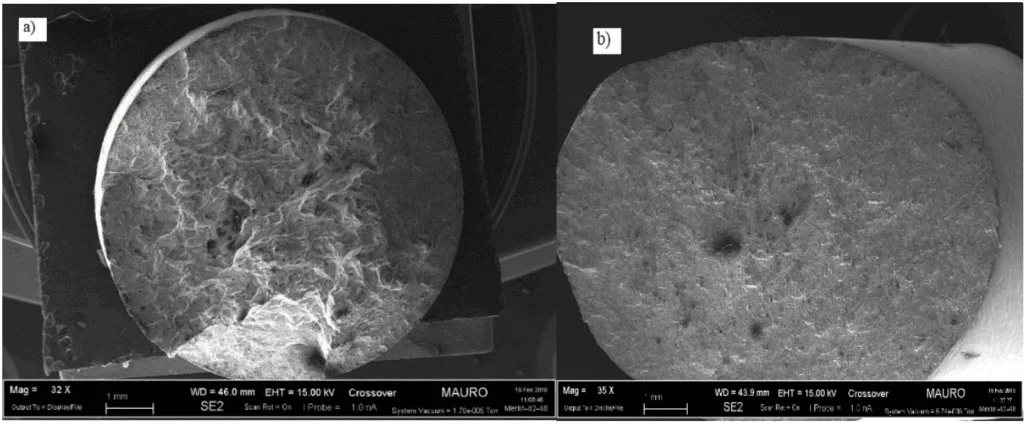
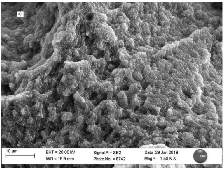
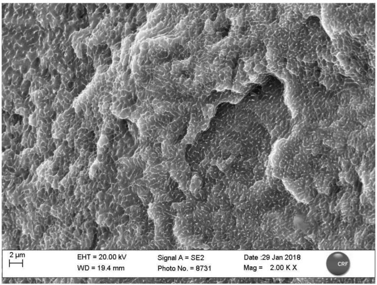
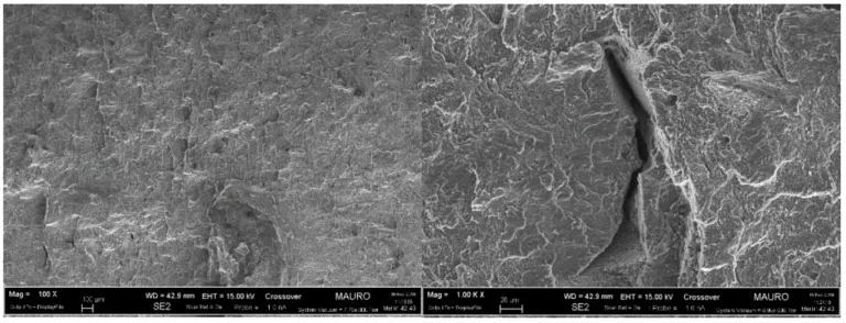
- 파괴 메커니즘: SEM은 낮은 배율에서 입계 간 연성 파괴(inter-domain ductile fracture), 특히 Z 시편의 경우(용융 풀 간 분리, Figure 52a)를 보여줌. 높은 배율에서는 입계 연성 파괴(미세 기공 합체, 딤플)가 관찰됨(Figure 53, Figure 55). 열처리는 결정립계에서 Si 편석(및 Mg2Si 형성 가능성)을 강화하여(Figure 57) 결정립 성장을 방해하지만 특성 변화에 기여함. Z 시편의 파괴는 층(약한 계면)에 수직으로 전파된 반면, XY 시편에서는 층(Figure 51)에 평행하게 전파됨.
- 경도: 경도는 이방성을 나타냄. 제작 방향(Z축)에 수직인 면이 평행한 면보다 일관되게 높은 HB 값을 보임(Table 11). 이는 다른 열 이력 때문임: 수직 면은 급속 냉각된 마지막 응고 층을 나타내는 반면, 평행 면은 제작 중 고온에 장시간 노출되어 응력 완화/연화가 발생할 수 있음. 열처리는 경도 값에 큰 영향을 미치지 않았으며, 이는 제작된 상태 부품의 경도가 주로 미세한 미세조직과 잔류 응력에 기인하고, 열처리 중 Mg2Si 석출이 응력 완화를 상쇄함을 시사함. SLM 경도는 표준 주조 AlSi10Mg와 비슷하거나 더 우수했지만, 석출 경화(T6) 또는 고압 다이캐스팅 및 시효 처리된 재료보다는 낮음(Table 12).
- 샤르피 충격: 명확한 이방성이 관찰됨. XY 평면 시편은 제작된 상태와 열처리된 상태 모두에서 Z축 시편보다 훨씬 더 많은 에너지를 흡수함(더 높은 인성) (Table 13). 이는 층 방향에 대한 균열 경로 때문임(Figure 59). 열처리는 두 방향 모두에서 흡수 에너지(파괴 인성)를 상당히 증가시켰으며, Z축 시편의 경우 약 5배 더 극적인 증가를 보임.
- 잔류 응력: XRD 분석 결과, 평행 및 수직 면 모두에서 압축 및 전단 응력의 복잡한 상태가 나타남(Figures 60, 61, 63, 64). 제작 방향에 수직인 면에서 더 높은 압축 응력이 측정되었으며, 이는 경도 결과 및 열 이력과 일치함. 과포화 고용체 상태의 Si 존재는 격자를 왜곡시켜 응력 측정의 절대 정확도에 영향을 미쳤을 가능성이 있음(d-간격 변화). 열처리는 압축/축 응력 성분에는 거의 영향을 미치지 않았지만, 전단 응력의 상당한 감소를 가져옴(Figure 62, 63, 64).
그림 이름 목록:
- Figure 1 : Comparison between AM costs and conventional methods ones[4]
- Figure 2 : Common metal additive manufacturing process[7]
- Figure 3 : EBM schematic representation
- Figure 4: schematic representation of LPBF process [8]
- Figure 5: schematic representation of SLM process
- Figure 6: scheme of LMD process
- Figure 7: Schematic representation of the SLM process
- Figure 8 The schematic of hatch angle in raster filling patterns
- Figure 9: different building orientation a) z plane b) c) xy plane
- Figure10: solid-liquid system wettability
- Figure11: schematic representation of water atomization process
- Figure 12 : schematic representation of plasma atomization process
- Figure 13 : schematic representation of centrifugal atomization
- Figure 14: schematic representation of gas atomization process
- Figure15: state diagram Al-Si
- Figure 16 : EOS M290 [27] system and its technical data
- Figure 17: Different scanning strategies.
- Figure18 : Eos M290 process parameters
- Figure 20: cubic and parallelepiped samples
- Figure 21: main samples geometries a), d) samples with building orientation along z-axes , b), c) samples with building orientation in x-y plane
- Figure 22: charpy test samples
- Figure 23 : tapping system
- Figure 24 : determination flow character through Hausner ratio e compress index
- FGUR E 25: ANALYSETTE 22 Nanotec
- Figure 26 : Archimede’s balance
- Figure 27 : CRF Metals Lab diffractometer
- Figure 28: Positions of XR source and detector for resisual stress measurements.
- Figure 29 Effect of stress on plane spacing in crystals with different orientation.
- Figure 30 Calculation of residual stress from the slope of the plot
- Figure 31 : inter-planar distance as a function of sin2 ψ a) Regular behavior b) ψ splitting c) Oscillatory -indicating the presence of an inhomogeneous stress/strain state within the material [30]
- Figure32: scheme of SEM
- Figure 33: tensile test sample a) before testing b) after testing
- Figure 34: MTS CITERION MODEL 43 machine
- Figure 35 : principle measurement of the Brinell hardness.
- Figure 36 : Brinnel EMCOTEST M5U 300/030 machine [ 30]
- Figure 37: ASTM E23 Charpy samples
- Figure 38 : SEM image of the two AlSi10Mg powders: A) first batch and B) second batch
- Figure 39 : particle size distribution; A virgin powder and B virgin powder
- Figure 40 : A and B virgin powder spectra
- Figure 41 : XRD spectrum of powder A: a) comparison among virgin powder, powder collected after DMLS job and as residual coming from nozzle; b) zoom on Si peak.
- Figure 42: jobs process parameters
- Figure 43: Job A as built and heat treated samples micrographs (magnification 50 x): on the left is presented the section parallel to the building direction, on the right the perpendicular one.
- Figure 44 :Typical microstructure morphology of Laser Melted parts: on the left the section parallel to the building direction (Z axis); on the right the section perpendicular to the building direction( Z axis)
- Figure 45 : Job A, Z samples as built and heat treated ,Stress-strain curves.
- Figure 46: Job A, XY samples as built and heat treated ,Stress-strain curves.
- Figure 47: Job B, Z samples as built and heat treated ,Stress-strain curves.
- Figure 48: Job B, XY samples as built and heat treated ,Stress-strain curves.
- Figure 49: Job C, XY samples as built and heat treated ,Stress-strain curves
- Figure 50: a) Z samples fracture surface b) XY samples fracture surface
- Figure 51 : Schematic representation of interactions between building orientation and the stress direction : a) Z samples b) XY samples
- Figure 52 : a) as built Z samples fracture surface (100x) b) as built XY samples fracture surface higher magnitude (100X)
- Figure 53 : as built Z sample fracture surface magnitude 1,50K,x
- Figure 54 : Al-Si phase diagram
- Figure 55 :Fracture surface os Z samples at high magnification: aluminum grains smaller than 2 µm with silicon segregation at the grain boundaries.
- Figure 56 :heat treated Z samples inter-domain fracture surfaces different magnitude
- Figure 57: Enhanced segregation at grain boundaries of silicon that hinders the aluminium grain growth during the heat treatment.
- Figure 58 :heat treated XY samples fracture surfaces, different magnifications
- Figure 59 : cross section of Charpy samples ,different layers orientation with respect to V notch for samples built along Z axis and on XY plane
- Figure 60: residual stress analysis on the perpendicular face of the as built sample
- Figure 61: residual stress analysis on the parallel face of the as built sample
- Figure 62: Temperature gradient influences on the formation of residual stress
- Figure 63: residual stress analysis on the perpendicular face of the heat treated sample
- Figure 64: residual stress analysis on the parallel face of the heat treated sample
7. 결론:
AlSi10Mg 합금 시편을 레이저 빔 용융(SLM) 기술로 생산하고 특성을 분석했습니다. 주요 결론은 다음과 같습니다:
- 모든 시편은 생산자(EOS) 데이터시트 값보다 낮은 밀도와 높은 기공률을 보였으며, 이는 용융 풀 가장자리에서의 불완전한 고화 때문일 가능성이 높습니다. 최종 밀도와 기공률은 열처리나 분말 층 두께에 크게 영향을 받지 않았습니다.
- 인장 시험 결과, 기계적 특성은 성장 방향, 열처리, 분말 층 두께에 따라 달라짐을 확인했습니다. Z축 시편은 XY 평면 시편보다 높은 인장 강도를 보였지만 항복 강도와 연신율은 더 낮았습니다. 응력 제거 열처리는 주로 연신율을 증가시키고 강도를 감소시켰으며, 특히 Z축 시편에서 그 효과가 두드러졌습니다. 두꺼운 분말 층은 열처리의 영향을 감소시켰습니다.
- 전자 현미경 관찰 결과, 결정립계에 실리콘이 편석된 매우 작은 알루미늄 결정립으로 구성된 미세조직이 나타났습니다. 파괴는 입계 간 및 입계 연성 파괴 메커니즘을 통해 발생했습니다. 열처리는 실리콘 편석을 강화하여 상당한 결정립 성장을 방해했습니다.
- 재료 이방성은 경도와 파괴 일(fracture work)에 영향을 미쳤습니다. 경도는 다른 열 이력으로 인해 성장 방향에 수직인 면에서 더 높았습니다. 응력 제거는 경도를 크게 변화시키지 않았습니다. 파괴 일(샤르피)은 XY 평면 시편에서 더 높았고 열처리 후 크게 증가했으며, 특히 Z축 시편에서 증가 폭이 컸습니다.
- 잔류 응력 분석 결과, 성장 방향에 수직인 면에서 더 높은 압축 및 전단 응력의 복잡한 상태가 나타났습니다. 고용체 상태의 실리콘 존재는 응력 평가 정확도에 영향을 미쳤습니다. 응력 제거 처리 후 전단 응력이 현저하게 감소하는 것이 관찰되었습니다.
8. 참고 문헌:
- [1] M. Javidani, J. Arreguin-Zavala, J. Danovitch, Y. Tian, and M. Brochu, “Additive Manufacturing of AlSi10Mg Alloy Using Direct Energy Deposition: Microstructure and Hardness Characterization,” J. Therm. Spray Technol., vol. 26, no. 4, pp. 587–597, 2017.
- [2] I. Campbell, D. Bourell, and I. Gibson, “Additive manufacturing: rapid prototyping comes of age,” Rapid Prototyp. J., vol. 18, no. 4, pp. 255–258, 2012.
- [3] S. H. Huang, P. Liu, A. Mokasdar, and L. Hou, “Additive manufacturing and its societal impact: A literature review,” International Journal of Advanced Manufacturing Technology, vol. 67, no. 5–8. pp. 1191–1203, 2013.
- [4] W. E. Frazier, “Metal additive manufacturing: A review,” Journal of Materials Engineering and Performance, vol. 23, no. 6. pp. 1917–1928, 2014.
- [5] N. Guo and M. C. Leu, “Additive manufacturing: Technology, applications and research needs,” Frontiers of Mechanical Engineering, vol. 8, no. 3. pp. 215–243, 2013.
- [6] S. Trouton, “A Deloitte series on additive manufacturing,” Deloitte Univ. Press, 2016.
- [7] V. Bhavar, P. Kattire, V. Patil, S. Khot, K. Gujar, and R. Singh, “A Review on Powder Bed Fusion Technology of Metal Additive Manufacturing,” Mater. Sci. Technol. 2014, pp. 251–262, 2014.
- [8] J.-P. Kruth, “Materials and Processing Issues in Powder Fusion Additive Manufacturing,” 2013.
- [9] R. M. Mahamood, E. T. Akinlabi, M. Shukla, and S. Pityana, “Material Efficiency of Laser Metal Deposited Ti6A14V: Effect of Laser Power,” Eng. Lett., vol. 21, no. 1, pp. 18–22, 2013.
- [10] B. Liu, R. Wildman, C. Tuck, I. Ashcroft, and R. Hague, “Investigation the effect of particle size distribution on processing parameters optimisation in selective laser melting process,” Int. solid Free. Fabr. Symp. an Addit. Manuf. Conf., no. mm, pp. 227–238, 2011.
- [11] A. Aversa et al., “Effect of Process and Post-Process Conditions on the Mechanical Properties of an A357 Alloy Produced via Laser Powder Bed Fusion,” Metals (Basel)., vol. 7, no. 3, p. 68, 2017.
- [12] K. H. Leitz et al., “Fundamental analysis of the influence of powder characteristics in Selective Laser Melting of molybdenum based on a multi-physical simulation model,” Int. J. Refract. Met. Hard Mater., vol. 72, no. December 2017, pp. 1–8, 2018.
- [13] D. Manfredi, F. Calignano, M. Krishnan, R. Canali, E. P. Ambrosio, and E. Atzeni, “From powders to dense metal parts: Characterization of a commercial alsimg alloy processed through direct metal laser sintering,” Materials (Basel)., vol. 6, no. 3, pp. 856–869, 2013.
- [14] N. Kang, P. Coddet, L. Dembinski, H. Liao, and C. Coddet, “Microstructure and strength analysis of eutectic Al-Si alloy in-situ manufactured using selective laser melting from elemental powder mixture,” J. Alloys Compd., vol. 691, pp. 316–322, 2017.
- [15] A. Aversa, “Development and Characterisation of Aluminium Alloys and Aluminium Matrix Composites Produced via Laser Powder Bed Fusion By,” 2017.
- [16] I. Yadroitsev, L. Thivillon, P. Bertrand, and I. Smurov, “Strategy of manufacturing components with designed internal structure by selective laser melting of metallic powder,” Appl. Surf. Sci., vol. 254, no. 4, pp. 980–983, 2007.
- [17] K. G. Prashanth et al., “Microstructure and mechanical properties of Al-12Si produced by selective laser melting: Effect of heat treatment,” Mater. Sci. Eng. A, vol. 590, pp. 153–160, 2014.
- [18] K. Kempen, L. Thijs, J. Van Humbeeck, and J.-P. Kruth, “Mechanical Properties of AlSi10Mg Produced by Selective Laser Melting,” Phys. Procedia, vol. 39, pp. 439–446, 2012.
- [19] L. Wang, J. Jue, M. Xia, L. Guo, B. Yan, and D. Gu, “Effect of the Thermodynamic Behavior of Selective Laser Melting on the Formation of In situ Oxide Dispersion-Strengthened Aluminum-Based Composites,” Metals (Basel)., vol. 6, no. 11, p. 286, 2016.
- [20] J. Kruth, P. Mercelis, J. Van Vaerenbergh, and T. Craeghs, “Feedback control of Selective Laser Melting,” Proc. 3rd Int. Conf. Adv. Res. Virtual Rapid Prototyp., pp. 1–7, 2007.
- [21] M. Entezarian, F. Allaire, P. Tsantrizos, and R. A. L. Drew, “Plasma atomization: A new process for the production of fine, spherical powders,” JOM, vol. 48, no. 6, pp. 53–55, 1996.
- [22] EOS GmbH - Electro Optical Systems, “Material information Compatibility DMLS Materials – EOSINT M 280,” p. 82152.
- [23] S. Hegde and K. N. Prabhu, “Modification of eutectic silicon in Al-Si alloys,” J. Mater. Sci., vol. 43, no. 9, pp. 3009–3027, 2008.
- [24] W. Li et al., “Effect of heat treatment on AlSi10Mg alloy fabricated by selective laser melting: Microstructure evolution, mechanical properties and fracture mechanism,” Mater. Sci. Eng. A, vol. 663, pp. 116–125, 2016.
- [25] N. T. Aboulkhair, N. M. Everitt, I. Ashcroft, and C. Tuck, “Reducing porosity in AlSi10Mg parts processed by selective laser melting,” Addit. Manuf., vol. 1, pp. 77–86, 2014.
- [26] B. Duman and M. C. Kayacan, “Doğrudan Metal Lazer Sinterleme / Ergitme Yöntemi ile İmal Edilecek Parçanın Mekanik Özelliklerinin Tahmini Predicting The Mechanical Properties Of The Part Produced By Direct Metal Laser Sintering / Melting Method,” 2017.
- [27] EOS GmbH, “EOS M290 Datasheet Status 09/2017,” 2017.
- [28] A. Popovich and V. Sufiiarov, “Metal Powder Additive Manufacturing,” New Trends 3D Print., 2016.
- [29] Fritsch, “Operating Instructions Analysette 22.”
- [30] M. Fitzpatrick, A. Fry, P. Holdway, F. Kandil, J. Shackleton, and L. Suominen, “Determination of Residual Stresses by X-ray Diffraction - Issue 2,” Meas. Good Pract. Guid., no. 52, p. 74, 2005.
- [31] JEOL, “Scanning Electron Microscope A To Z,” Serv. Adv. Technol., p. 32, 2006.
- [32] 1.Rosenthal, I., Stern, A. & Frage, N. Strain rate sensitivity and fracture mechanism of AlSi10Mg parts produced by Selective Laser Melting. Mater. Sci. Eng. A 682, 509–517 (2017).
- [33] 1.Mertens, A., Dedry, O., Reuter, D., Rigo, O. & Lecomte-Beckers, J. THERMAL TREATMENTS OF AlSi10Mg PROCESSED BY LASER BEAM MELTING. 1007–1016
- [34] 1.Aboulkhair, N. T., Everitt, N. M., Ashcroft, I. & Tuck, C. Reducing porosity in AlSi10Mg parts processed by selective laser melting. Addit. Manuf. 1, 77–86 (2014).
9. 저작권:
- 본 자료는 "Giulia Di Matteo"의 논문입니다. "[Selective laser melting aluminum alloys for automotive component]"를 기반으로 합니다.
- 논문 출처: 해당 없음 (석사 학위 논문, Politecnico di Torino)
본 자료는 상기 논문을 바탕으로 요약되었으며, 상업적 목적의 무단 사용을 금지합니다.
Copyright © 2025 CASTMAN. All rights reserved.


