본 소개 자료는 "Energies (MDPI)"에서 발행된 "Model Characterization of High-Voltage Layer Heater for Electric Vehicles through Electro-Thermo-Fluidic Simulations" 논문을 기반으로 합니다.
1. 개요:
- 논문명: Model Characterization of High-Voltage Layer Heater for Electric Vehicles through Electro-Thermo-Fluidic Simulations
- 저자: Kwon Joong Son
- 발행 연도: 2024
- 발행 학술지/학회: Energies
- 키워드: high-voltage heater; layer heater; computational fluid dynamics; transient heat transfer; multiphysics; transfer function modeling
2. 초록:
본 논문은 전기 자동차(EVs) 및 플러그인 하이브리드 전기 자동차(PHEVs)를 포함한 친환경 차량용으로 설계된 HVLH (high-voltage layer heater)의 모델링 및 분석에 중점을 두며, 전기, 열, 유체 역학 측면을 다루는 multiphysics 시뮬레이션을 통해 수행됩니다. HVLHs 생산 및 실험적 특성화에 상당한 비용과 시간이 소요되므로 개발 단계에서는 시뮬레이션 및 물리적 모델링 방법이 선호됩니다. 본 연구는 전기 영역 내 TFE (heating element)의 열 경계 조건을 개별적으로 모델링하여 Joule heating 계산 및 transient conjugate heat transfer 분석을 가능하게 하는 선구적인 연구입니다. 또한, 본 연구는 HVLH 구성 요소에 대한 transfer function modeling 적용을 시작하여 HVAC (heating, ventilation, and air conditioning) 시스템의 광범위한 맥락으로 그 사용을 확장합니다. 입력 전압 및 유동 조건에 따른 Joule heating 및 온도장 계산을 포함하는 시뮬레이션 결과는 실험 데이터와 매우 유사합니다. 도출된 transfer function은 회귀 매개변수와 함께 시스템의 동적 거동을 정밀하게 예측합니다. 본 연구에서 제시된 시뮬레이션 기반 모델링 접근 방식은 친환경 전기 난방 시스템의 설계 및 제어를 크게 발전시켜 지속 가능하고 비용 효율적인 솔루션을 제공합니다.
3. 서론:
전기 자동차(EVs) 및 플러그인 하이브리드 전기 자동차(PHEVs)는 엔진이나 전기 모터의 폐열에 지속적으로 의존할 수 없으므로 실내 난방, 성에 제거 및 배터리 예열을 위해 배터리 구동 히터가 필요합니다. HVHs (High-voltage heaters)가 일반적으로 사용되며, PTC (positive temperature coefficient) 히터가 널리 사용되는 유형입니다. PTC 히터는 자기 제한적 온도 특성을 제공하지만, 저온에서 상당한 전력을 소비하고 소형 경량 설계 달성에 한계가 있습니다. 본 논문은 PTC 히터의 한계를 극복하기 위해 설계된 silver-palladium 합금 저항층을 활용하는 대안적인 HVH 유형에 중점을 둡니다. 이 HVLH (high-voltage layer heater)는 열교환기로 작동하며, 적층된 TFE (thick-film heating element)를 통해 냉각수를 가열합니다. 이는 경량 구조, 향상된 열 출력 및 효율성, 쉽게 구할 수 있는 재료 사용(지속 가능성 향상), 그리고 잠재적인 에너지 절약(PTC 히터 대비 초기 예열 단계에서 약 18% [1])과 같은 이점을 제공합니다. 열 출력은 온도 센서와 PWM (pulse width modulation) 제어를 사용하여 제어됩니다.
4. 연구 요약:
연구 주제의 배경:
EVs 및 PHEVs와 같은 친환경 차량에는 효율적이고 컴팩트한 난방 시스템이 필요합니다. 기존 PTC 히터에는 단점이 있어, silver-palladium 합금 저항층 기반의 HVLH와 같은 대안적인 HVH 기술에 대한 연구가 진행되고 있습니다. 이러한 HVLHs는 크기, 무게, 효율성 및 재료 지속 가능성 측면에서 이점을 제공합니다.
선행 연구 현황:
HVLHs에 대한 이전 학술 연구는 주로 유체 유동 및 열전달의 수치 해석을 사용한 가상 성능 검증 및 설계 최적화에 중점을 두었으며, 종종 정상 상태 조건에 집중했습니다 [9,10]. 저자의 이전 연구를 포함한 일부 연구[11,12]에서는 TFE 구조의 모델링을 개선하고 Joule heating 계산을 포함했습니다. 그러나 이전 연구의 중요한 한계는 정상 상태 분석에 의존한다는 점이며, 이는 효과적인 제어기 설계 및 HVAC 시스템으로의 시스템 수준 통합에 중요한 동적 거동 및 과도 응답을 적절히 포착하지 못합니다.
연구 목적:
본 연구의 목적은 HVLH의 과도 multiphysics 해석을 통해 시간 응답 데이터를 확보하고 HVLH에 대한 정확한 transfer function model을 개발하는 것입니다. 이 모델은 HVLH의 동적 거동 예측을 용이하게 하고, 제어 전략 개발 및 구현을 위해 시스템 수준 HVAC 시뮬레이션(예: Modelica 또는 Simulink 사용)에 통합하는 것을 목표로 합니다.
핵심 연구:
본 연구의 핵심은 대칭적인 서펜타인 유로를 특징으로 하는 특정 HVLH 설계에 대한 포괄적인 electro-thermo-fluidic 시뮬레이션을 포함합니다. 이는 다음을 포함합니다:
- 전기 영역 내 TFE (thick-film heating element)의 열 경계 조건에 대한 개별 모델링.
- 인가 전압에 기반한 Joule heating 계산.
- 다양한 냉각수 유동 조건에서의 transient conjugate heat transfer 분석.
- HVLH의 동적 거동을 특성화하는 시뮬레이션된 스텝 응답 데이터로부터 transfer function model 도출.
5. 연구 방법론
연구 설계:
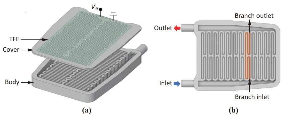
연구된 HVLH 장치는 이전 모델[11]의 형상과 전체 치수(177.4 mm × 251.0 mm × 20.5 mm)를 유지하면서 대칭적인 서펜타인 유로를 통합합니다.
- 구조: 다이캐스팅 가능한 주요 구조 요소를 볼트로 조립하여 대량 생산을 위해 설계되었습니다. 얇은 전도성(silver-palladium, Ag-Pd) 및 절연성(alumina, Al2O3) 층이 aluminum alloy (ALDC2) 커버 플레이트에 스크린 인쇄됩니다.
- Heating Element (TFE): Ag-Pd 저항 발열층(두께 8 µm)은 상부(30 µm) 및 하부(120 µm) alumina (Al2O3) 절연층 사이에 끼워져 있습니다. 냉각수에 잠기지 않고 히터의 외부 표면에 위치합니다. 전기 연결은 단일 입력 단자와 접지 단자를 통해 이루어집니다.
- 유로: 단일 원형 단면 입구에서 시작되는 12개의 평행 분기로 구성됩니다. 각 분기는 직사각형 단면을 가진 4중 거울 대칭 서펜타인 경로를 가집니다. 유로 공동 부피는 183.2 cm³입니다.
- 재료:
- 히터 본체 및 커버 플레이트: Aluminum alloy Al-Si-Mg (ALDC2)
- 저항 발열체: Silver-palladium (Ag-Pd)
- 절연층: Alumina (Al2O3)
- 냉각수: Table 1에 명시된 특성.
데이터 수집 및 분석 방법:
Multiphysics 시뮬레이션은 COMSOL Multiphysics 6.0과 그 Composite Materials, AC/DC, CFD, Heat Transfer 모듈을 사용하여 수행되었습니다.
- 지배 방정식 및 모델:
- 유체 역학: 정상, 비압축성, 난류 유동은 SST (shear stress transport) k-ω model(논문의 식 (1) 및 (2))을 사용하여 모델링되었습니다.
- 정전기학 및 Joule Heating: 전위(V)에 대한 Laplace equation (∇²V = 0), 전기장 강도(E = -∇V), 전류 밀도(J)에 대한 Ohm's law (J = σE), 그리고 Joule heating power generation (Qe = E·J, 식 (4)).
- 열전달: 전도성 Ag-Pd 매질에 대한 시간 의존적 에너지 평형 방정식(식 (3))으로, 열전도 및 대류를 통합합니다. 고체와 유체 영역 간의 CHT (conjugate heat transfer)는 Kays–Crawford turbulent Prandtl number (Prt, 식 (5))를 사용하여 모델링되었습니다.
- 메싱: 유체 및 구조적 고체 영역은 3D 요소를 사용하여 이산화되었으며, 얇은 복합 TFE 구조에는 평면 적층 쉘 요소가 사용되었습니다. 이로 인해 32,010,895개의 3D 요소(유체 24,856,397개, 고체 7,154,498개)와 24,704개의 적층 쉘 요소가 생성되었습니다.
- 경계 조건:
- 외부 알루미늄 표면(입구/출구 파이프 제외): 대류 계수 5.0 W/m²·K 및 주변 온도 25 °C의 대류 열전달.
- 입구 및 출구 파이프: 절연된 것으로 가정.
- 냉각수 입구: 온도 25 °C, 유량 5, 10, 15, 20 LPM (Liters Per Minute).
- 입력 전압: 0.01초 동안 0V에서 350V로 증가하는 시그모이드형 스텝 신호(Figure 2b).
- 시뮬레이션 절차:
- 정상 상태 난류 유동장을 얻기 위한 초기 CFD 분석.
- 이후 전기장 및 Joule heating의 영향을 고려하여 60초 동안 동적 CHT 분석(데이터는 1초 간격으로 기록).
- Transfer Function Modeling:
- HVLH는 1차 LTI (linear time-invariant) 시스템으로 모델링되었습니다.
- 입구에서 출구까지 냉각수 온도 증가(∆T)에 대한 스텝 응답은 다음과 같습니다: ∆T(t) = (1 - e^(-t/tc)) ∆Tss (식 (6)), 여기서 tc는 time constant이고 ∆Tss는 정상 상태 온도 증가입니다.
- 해당 transfer function (TF)은 다음과 같습니다: TF = ∆T(s)/Vin = KDC / (tcs + 1) (식 (7)), 여기서 Vin은 입력 전압 진폭이고 KDC는 DC gain입니다 (KDC = ∆Tss / Vin, 식 (8)).
- KDC와 tc는 각 유량에 대한 시뮬레이션 데이터로부터 결정되었습니다.
- 체적 유량 Q (LPM)의 함수로 KDC와 tc를 표현하기 위해 역비례 함수 f(Q) = a/Q + b (식 (9))를 사용하여 회귀 분석을 수행했습니다.
- Q를 통합한 최종 transfer function은 다음과 같이 도출되었습니다: TF(s; Q) = 0.2687 / ((1.969Q + 43.68)s + Q) (식 (10)).
연구 주제 및 범위:
본 연구는 전기 자동차용 HVLH의 모델 특성화에 중점을 두었습니다. 이는 다음을 포함합니다:
- electro-thermo-fluidic 측면을 다루는 multiphysics 시뮬레이션 모델 개발.
- 다양한 냉각수 유량(5, 10, 15, 20 LPM)에서 스텝 전압 입력 하에 HVLH의 과도 거동 분석.
- 전기 영역에서 전도성 발열층을 개별적으로 모델링하여 Joule heating 계산.
- transient conjugate heat transfer 조사.
- 광범위한 HVAC 시스템 모델링 및 제어 설계에 사용할 수 있도록 HVLH에 대한 transfer function model 도출 및 검증.
6. 주요 결과:
주요 결과:
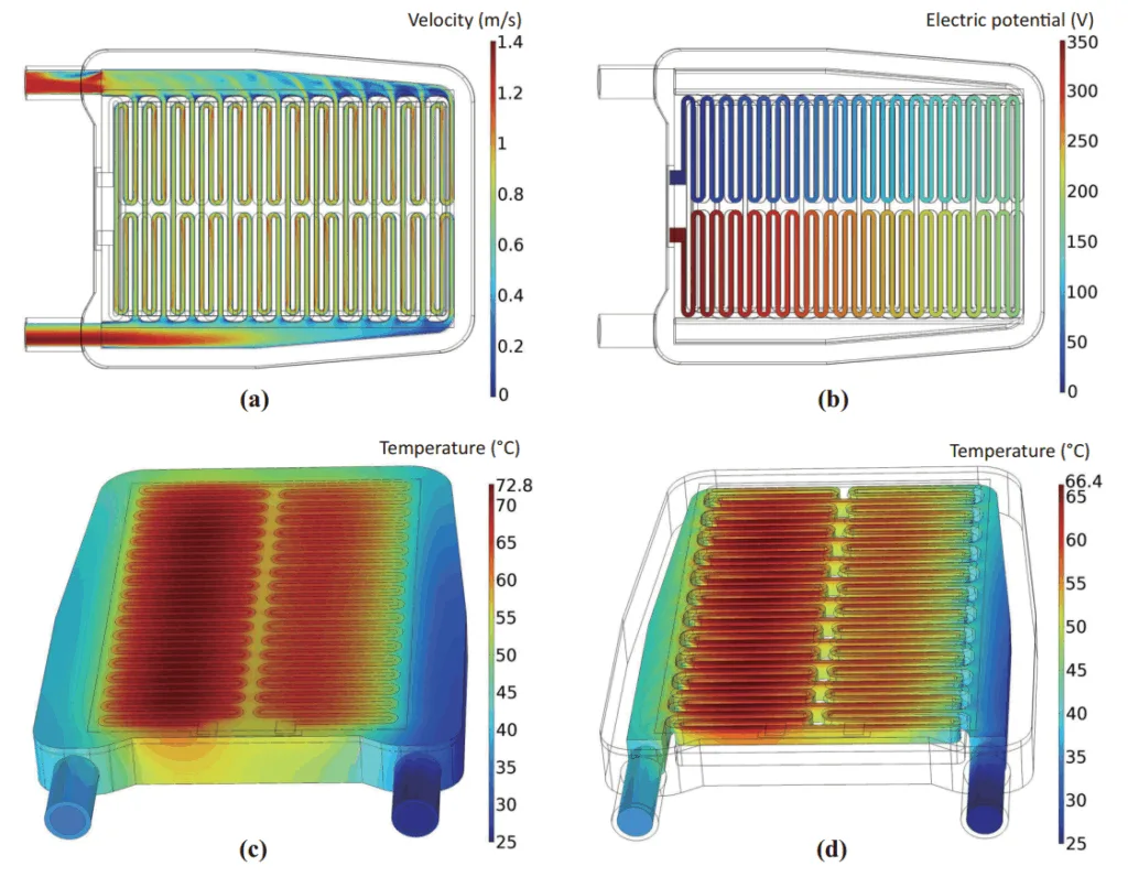
- 유동 및 온도장: 시뮬레이션은 5, 10, 15, 20 LPM의 냉각수 유량에 대한 정상 상태 유동장과 과도 전기장 및 온도장을 제공했습니다. 전기장은 스텝 전압 입력 직후 거의 포화 상태에 도달했지만, 온도장은 정상 상태에 도달하기 전에 과도 응답을 보였습니다.
- 10 LPM 유량(1.67 × 10⁻⁴ m³/s)에서 60초 경과 시:
- 속도장은 입구에서 멀리 떨어진 분기에서 유속이 감소하는 것을 보여주었으며, 유동 막힘은 관찰되지 않았습니다 (Figure 3a).
- TFE 전체에 걸쳐 일관된 전압 강하가 관찰되었습니다 (Figure 3b).
- TFE에서 최고 온도는 72.8 °C에 도달했습니다 (Figure 3c).
- 출구에서의 평균 냉각수 온도는 34.4 °C로, 입구 온도 25 °C에서 9.4 °C 증가한 값입니다 (Figure 3d).
- 10 LPM 유량(1.67 × 10⁻⁴ m³/s)에서 60초 경과 시:
- 과도 열 응답:
- 입구와 출구 사이의 정상 상태 온도 차이(∆Tss)는 냉각수 유량이 증가함에 따라 감소했습니다 (Figure 4a).
- 유량이 높을수록 ∆Tss의 초기 변화가 더 빠르고 정상 상태에 도달하는 시간이 짧아졌습니다.
- 실험 데이터와의 비교: 시뮬레이션된 ∆Tss 값은 [28]의 실험 데이터와 잘 일치했으며, 다양한 유량에서 1.4%에서 10.5% 범위의 불일치를 보였습니다 (Figure 4b).
- Transfer Function Model:
- HVLH의 동적 거동은 1차 LTI 시스템으로 잘 표현되었습니다.
- Transfer function 매개변수(DC gain KDC, time constant tc, rise time tr, settling time ts)는 각 유량에 대한 시뮬레이션 데이터로부터 도출되었습니다 (Table 2). 예:
- 5 LPM에서: KDC = 0.0537 °C/V, tc = 10.3 s.
- 20 LPM에서: KDC = 0.0133 °C/V, tc = 3.71 s.
- 적합된 transfer function 곡선은 시간 의존적 시뮬레이션 데이터와 매우 유사했습니다 (Figure 5).
- 회귀 분석을 통해 유량 Q (LPM)의 함수로 KDC 및 tc에 대한 관계가 도출되었습니다 (Figure 6):
- KDC(Q) = 0.2687 / Q
- tc(Q) = 43.68 / Q + 1.696
- 유량 Q를 통합한 일반화된 transfer function은 다음과 같이 공식화되었습니다:
TF(s; Q) = 0.2687 / ((1.969Q + 43.68)s + Q) (식 (10)). - 도출된 transfer function model은 스텝 응답 및 PWM 제어 시뮬레이션을 위한 블록 다이어그램으로 시연되어 시스템 수준 분석에서의 유용성을 강조했습니다 (Figure 7).
그림 목록:
- Figure 1. HVLH schematic diagram: (a) disassembled illustration of heater consisting of main body with serpentine walls and cover plate with screen-printed heating layer; (b) heater body including symmetric serpentine flow channels with twelve branches in parallel.
- Figure 2. Preprocessing of electro-thermo-fluidic simulation: (a) meshed elements zoomed-in around the coolant inlet and (b) Sigmoid-based step voltage input function.
- Figure 3. Simulation results for inlet flow rate of 10 LPM at 60 s: (a) steady-state velocity magnitude contour plot at the middle cross-section of serpentine flow channels; (b) electric potential contour plot on the conductive heating layer; (c) temperature contour plot on the solid surface; (d) temperature contour plot on the fluid surface.
- Figure 4. Time-dependent thermal analysis results: (a) temperature difference versus time curve for different coolant flow rates, with data points collected every 2 s; (b) bar graphs comparing simulated and experimental results for steady-state temperature increase from inlet to outlet.
- Figure 5. Transfer function curves fitted against simulation data for various LPMs.
- Figure 6. Results from curve fitting of transfer function parameters for (a) steady-state gain and (b) time constant.
- Figure 7. PWM control of high-voltage heat using the transfer function model: (a) block diagram schematic; (b) step response versus PWM response curves.
7. 결론:
본 연구는 HVLH의 과도 electro-thermo-fluidic 거동을 특성화하고 정확한 transfer function을 도출하기 위한 포괄적인 모델링 및 시뮬레이션 접근 방식을 성공적으로 제시했습니다.
주요 기여는 다음과 같습니다:
- 향상된 HVLH 모델링: 본 연구는 전기 영역에서 전도성 발열층을 개별적으로 모델링하여 HVLH를 모델링하고 시뮬레이션한 최초의 연구입니다. 이를 통해 Joule heating의 정확한 계산과 transient conjugate heat transfer 분석이 가능해져 열 성능 및 전력 소비 예측이 향상됩니다.
- 선구적인 Transfer Function 개발: 본 연구는 HVLH 구성 요소의 transfer function 모델링을 선도하며, 이는 시스템 수준 HVAC 모델링에 통합하고 전기 자동차 난방 시스템을 위한 효과적인 제어 전략을 개발 및 구현하는 데 중요합니다.
- 고정밀 모델 검증: Transfer function 및 해당 매개변수에 대한 회귀 분석 결과, 시뮬레이션 데이터를 높은 정밀도로 재현함을 보여주어 HVAC 시스템 성능 예측 모델의 신뢰성을 강조합니다.
본 연구는 모델링 및 시뮬레이션을 위한 견고한 방법론을 제공함으로써 전기 자동차 난방 시스템의 개발 및 관리를 크게 발전시킵니다. 이는 HVLHs의 설계 및 향상에 기여하고 빠르게 성장하는 전기 자동차 부문에서 효과적인 난방 솔루션 채택을 촉진합니다. 잠재적인 향후 연구 방향으로는 수정된 유로 및 TFE 구성을 갖는 새로운 HVLH 모델 개발, 그리고 실제 적용을 위해 transfer function model을 추가로 검증하고 개선하기 위한 HVLH를 포함한 전체 HVAC 시스템의 포괄적인 동적 모델링 및 분석이 포함될 수 있습니다.
8. 참고문헌:
- [1] Li, B.; Kuo, H.; Wang, X.; Chen, Y.; Wang, Y.; Gerada, D.; Worall, S.; Stone, I.; Yan, Y. Thermal Management of Electrified Propulsion System for Low-Carbon Vehicles. Automot. Innov. 2020, 3, 299–316.
- [2] Lei, S.; Xin, S.; Liu, S. Separate and Integrated Thermal Management Solutions for Electric Vehicles: A Review. J. Power Sources 2022, 550, 232133.
- [3] Park, M.H.; Kim, S.C. Heating Performance Characteristics of High-Voltage PTC Heater for an Electric Vehicle. Energies 2017, 10, 1494.
- [4] Park, M.H.; Kim, S.C. Effects of Geometric Parameters and Operating Conditions on the Performance of a High-Voltage PTC Heater for an Electric Vehicle. Appl. Therm. Eng. 2018, 143, 1023–1033.
- [5] Shin, Y.H.; Ahn, S.K.; Kim, S.C. Performance Characteristics of PTC Elements for an Electric Vehicle Heating System. Energies 2016, 9, 813.
- [6] Paunović, V.; Mitić, V.; Đorđević, M.; Prijić, Z. Electrical Properties of Rare Earth Doped BaTiO3 Ceramics. In Proceedings of the 2017 IEEE 30th International Conference on Microelectronics (MIEL), Nis, Serbia, 9–11 October 2017; pp. 183–186.
- [7] Cap, C.; Hainzlmaier, C. Layer Heater for Electric Vehicles. ATZ Worldw. 2013, 115, 16–19.
- [8] Stifel, T. Optimization and Protection of Traction Batteries with an HV Coolant Heater. ATZ Worldw. 2021, 123, 44–47.
- [9] Dong, F.; Feng, Y.; Wang, Z.; Ni, J. Effects on Thermal Performance Enhancement of Pin-Fin Structures for Insulated Gate Bipolar Transistor (IGBT) Cooling in High Voltage Heater System. Int. J. Therm. Sci. 2019, 146, 106106.
- [10] Dong, F.; Wang, Z.; Feng, Y.; Ni, J. Numerical Study on Flow and Heat Transfer Performance of Serpentine Parallel Flow Channels in a High Voltage Heater System. Therm. Sci. 2022, 26, 735–752.
- [11] Son, K.J. Thermo-Fluid Simulation for Flow Channel Design of 7 kW High-Voltage Heater for Electric Vehicles. J. Korea Converg. Soc. 2022, 13, 191–196.
- [12] Son, K.J. Optimal Power Distribution of High-Voltage Coolant Heater for Electric Vehicles through Electro-Thermofluidic Simulations. Int. J. Automot. Technol. 2023, 24, 995–1003.
- [13] Bellocchi, S.; Leo Guizzi, G.; Manno, M.; Salvatori, M.; Zaccagnini, A. Reversible Heat Pump HVAC System with Regenerative Heat Exchanger for Electric Vehicles: Analysis of Its Impact on Driving Range. Appl. Therm. Eng. 2018, 129, 290–305.
- [14] Basciotti, D.; Dvorak, D.; Gellai, I. A Novel Methodology for Evaluating the Impact of Energy Efficiency Measures on the Cabin Thermal Comfort of Electric Vehicles. Energies 2020, 13, 3872.
- [15] Dvorak, D.; Basciotti, D.; Gellai, I. Demand-Based Control Design for Efficient Heat Pump Operation of Electric Vehicles. Energies 2020, 13, 5440.
- [16] Kulkarni, A.; Brandes, G.; Rahman, A.; Paul, S. A Numerical Model to Evaluate the HVAC Power Demand of Electric Vehicles. IEEE Access 2022, 10, 96239–96248.
- [17] Menter, F.R. Two-Equation Eddy-Viscosity Turbulence Models for Engineering Applications. AIAA J. 1994, 32, 1598–1605.
- [18] Menter, F.R.; Kuntz, M.; Langtry, R. Ten Years of Industrial Experience with the SST Turbulence Model. Turbul. Heat Mass Transf. 2003, 4, 625–632.
- [19] Speziale, C.G.; Abid, R.; Anderson, E.C. Critical Evaluation of Two-Equation Models for near-Wall Turbulence. AIAA J. 1992, 30, 324–331.
- [20] Rivero, E.P.; Granados, P.; Rivera, F.F.; Cruz, M.; González, I. Mass Transfer Modeling and Simulation at a Rotating Cylinder Electrode (RCE) Reactor under Turbulent Flow for Copper Recovery. Chem. Eng. Sci. 2010, 65, 3042–3049.
- [21] Weigand, B.; Ferguson, J.R.; Crawford, M.E. An Extended Kays and Crawford Turbulent Prandtl Number Model. Int. J. Heat Mass Transf. 1997, 40, 4191–4196.
- [22] Luo, D.; Wang, R.; Yan, Y.; Sun, Z.; Zhou, W.; Ding, R. Comparison of Different Fluid-Thermal-Electric Multiphysics Modeling Approaches for Thermoelectric Generator Systems. Renew. Energy 2021, 180, 1266–1277.
- [23] Jouhara, H.; Żabnieńska-Góra, A.; Khordehgah, N.; Doraghi, Q.; Ahmad, L.; Norman, L.; Axcell, B.; Wrobel, L.; Dai, S. Thermoelectric Generator (TEG) Technologies and Applications. Int. J. Thermofluids 2021, 9, 100063.
- [24] Son, K.J. Thermo-Electro-Fluidic Simulation Study of Impact of Blower Motor Heat on Performance of Peltier Cooler for Protective Clothing. Energies 2023, 16, 4052.
- [25] Drumheller, D.S. Hypervelocity Impact of Mixtures. Int. J. Impact Eng. 1987, 5, 261–268.
- [26] Son, K.J.; Fahrenthold, E.P. Impact Dynamics Simulation for Magnetorheological Fluid Saturated Fabric Barriers. J. Comput. Nonlinear Dyn. 2024, 19, 061002.
- [27] Zhang, X.; Jane Wang, Q.; He, T.; Liu, Y.; Li, Z.; Kim, H.J.; Pack, S. Fully Coupled Thermo-Viscoelastic (TVE) Contact Modeling of Layered Materials Considering Frictional and Viscoelastic Heating. Tribol. Int. 2022, 170, 107506.
- [28] Kwon, B.W. Development of 7 kW-Class Thick Film Resistance Heating Electric Heater (10% Weight Reduction) for Lighter Green Vehicle Cooling, Heating and HVAC System; Final Project Report (Written in Korean) No. P0017526; Korean Ministry of Trade, Industry and Energy (MOTIE): Sejong, Republic of Korea, 2023.
- [29] Franlkin, G.F.; Powell, J.D.; Emami-Naeini, A. Feedback Control of Dynamic Systems, 8th ed.; Higher Education, Inc.: Upper Saddle River, NJ, USA, 2018; pp. 137–142.
- [30] Shin, Y.H.; Sim, S.; Kim, S.C. Performance Characteristics of a Modularized and Integrated PTC Heating System for an Electric Vehicle. Energies 2016, 9, 18.
9. 저작권:
- 본 자료는 "Kwon Joong Son"의 논문입니다. "Model Characterization of High-Voltage Layer Heater for Electric Vehicles through Electro-Thermo-Fluidic Simulations"을 기반으로 합니다.
- 논문 출처: https://doi.org/10.3390/en17122935
본 자료는 위 논문을 바탕으로 요약되었으며, 상업적 목적의 무단 사용을 금합니다.
Copyright © 2025 CASTMAN. All rights reserved.