본 입문서는 "퀸즐랜드 대학교(University of Queensland)"에서 발행된 "[Mechanisms of Leaker Formation in Aluminium High Pressure Die Casting]" 논문을 기반으로 합니다.
1. 개요:
- 제목: Mechanisms of Leaker Formation in Aluminium High Pressure Die Casting (알루미늄 고압 다이캐스팅에서의 누설 결함 형성 메커니즘)
- 저자: Stephen Thompson
- 발행 연도: 1998년
- 발행 학술지/학회: University of Queensland (Thesis for Masters of Engineering Science by Research)
- 키워드: 논문에 명시되지 않음.
2. 초록:
이 보고서에서는 일반적인 경우와 특정 알루미늄 고압 다이캐스팅에서의 누설 결함 형성 메커니즘에 대한 이해를 전개합니다. 이러한 이해는 여러 단계를 통해 개발됩니다.
기존 발표된 연구 검토를 통해 고압 다이캐스팅에서 누설 결함 형성에 기여할 수 있는 주조 결함을 결정합니다. 이러한 각 결함과 주조 내압 기밀성에 미치는 영향에 대한 문헌 검토에 더욱 집중합니다. 검토된 결함은 콜드 플레이크, 콜드 셧, 드래그 마크, 가스 기공, 산화막, 입자상 개재물, 표면층을 제거하거나 손상시키는 2차 작업, 수축 기공, 소착 및 표면 균열입니다. 이 정보는 특정 주조에서 누설의 "근본 원인"을 결정하는 데 도움이 될 "결함 트리(Fault Tree)"를 형성하기 위해 편집됩니다.
그런 다음 자동차용 워터 인렛 주물 관찰을 통해 특정 사례에서 누설의 가능성 있는 근본 원인을 결정합니다. 누설의 근본 원인이 될 수 있는 결함으로는 콜드 셧, 가스 기공, 수축 기공, 휘발성 유체로 인한 표면 기공, 드래그 마크 및 표면 균열이 발견되었습니다. 주물의 중요 부위 가공 또한 누설 형성 가능성을 높이는 것으로 나타났습니다.
이러한 결함 중 콜드 셧이 누설의 가장 중요한 근본 원인으로 나타났습니다. 콜드 셧 및 누설 발생에 대한 공정 변수의 영향을 분석하기 위해, 누설 발생을 증가시키도록 금형 및 용탕 온도를 조작하는 구조화된 실험을 수행했습니다. 결과는 콜드 셧의 발생 및 정도와 누설 발생 사이에 강한 연관성을 보여줍니다. 또한, 결과는 금형 온도와 누설 발생 사이의 연관성을 입증합니다.
마지막으로, 자동차용 워터 인렛 주물에서 누설 발생을 줄이기 위한 여러 전략이 제안되고 추가 연구 가능성에 대한 제언이 이루어집니다.
3. 서론:
이 문서는 Stephen Thompson의 1998년 석사 논문 "알루미늄 고압 다이캐스팅에서의 누설 결함 형성 메커니즘"에 제시된 주요 연구 결과 및 방법론을 요약합니다. 원 논문은 자동차용 워터 인렛 주물을 특정 사례 연구로 하여 알루미늄 고압 다이캐스팅에서 "누설" 결함이 발생하는 이유에 대한 포괄적인 조사를 제공합니다. 본 요약은 다이캐스팅 기술 분야의 업계 전문가 및 연구자에게 적합한 핸드북 스타일 형식으로 핵심 개념, 연구 진행 과정 및 결론을 제시하는 것을 목표로 합니다.
4. 연구 요약:
연구 주제의 배경:
고압 다이캐스팅은 주물당 비용이 저렴하고 생산율이 높아 복잡한 부품을 제조하는 데 일반적인 공정입니다. 얇은 벽 두께와 높은 치수 정확도를 가진 부품을 생산할 수 있습니다. 그러나 주물, 특히 유체를 담거나 통과시키도록 의도된 주물은 압력 하에서 유체가 주물 벽을 통과하도록 하는 결함인 "누설(leakers)"로 인해 어려움을 겪을 수 있습니다. 이러한 결함은 불량 처리되거나 밀봉제 함침이 필요하게 됩니다. 본 연구는 누설 결함이 발생하기 쉬운 알루미늄 합금 CA313으로 제작된 자동차용 워터 인렛 주물에 초점을 맞춥니다. 누설 결함 형성은 종종 다른 주조 결함의 조합으로 인해 발생합니다.
이전 연구 현황:
논문의 제2장에서는 고압 다이캐스팅에서 누설 결함 형성에 기여할 수 있는 주조 결함을 식별하기 위해 이전에 발표된 문헌을 검토합니다. 문헌에 따르면 누설이 발생하려면 표면층과 주물 중심을 통과하는 경로가 존재해야 합니다. 잠재적 원인으로 식별된 결함은 다음과 같습니다:
- Cold Flakes (콜드 플레이크)
- Cold Shuts (콜드 셧)
- Drag Marks (드래그 마크)
- Gas Porosity (가스 기공)
- Oxide Films (산화막)
- Particulate Inclusions (입자상 개재물)
- Secondary Operations that Remove or Damage the Surface Layer (표면층을 제거하거나 손상시키는 2차 작업)
- Shrinkage Porosity (수축 기공)
- Soldering (소착)
- Surface Cracks (표면 균열)
검토를 통해 이 정보를 "결함 트리(Fault Tree)"(Figure 2.18)로 편집하여 누설의 근본 원인을 파악하는 데 도움을 주었습니다. 각 잠재적 원인에 대해 문헌은 다음 사항을 조사했습니다:
- 누설을 유발할 가능성이 있는 조건.
- 형성 메커니즘.
- 발생 감소 전략.
논문은 가스 기공과 같은 일부 결함은 종종 누설의 주요 원인으로 간주되지 않지만(분리된 기포를 형성하는 경향이 있으므로), 다른 결함과의 상호 작용이나 특정 형성 메커니즘(예: 휘발성 이형제로 인한)이 누설 경로를 유발할 수 있다고 지적합니다. 수축 기공, 특히 응고 범위가 긴 아공정 합금의 수지상정 간 기공은 표면층이 손상될 때 누설 경로를 만들 수 있는 일반적인 특징으로 식별됩니다.
연구 목적:
본 연구는 다음과 같은 목표를 가졌습니다 (6페이지에 명시됨):
I. 누설 결함 형성의 일반적인 메커니즘을 결정하기 위해 기존 발표된 연구를 종합한다.
II. 워터 인렛 주물의 공정 및 주물 관찰을 통해 누설 형성의 가능성 있는 메커니즘을 결정한다.
III. 발표된 문헌을 기반으로 워터 인렛 주물의 누설 형성에 중요한 영향을 미칠 가능성이 있는 변수를 제안한다.
IV. 제II단계에서 결정된 메커니즘과 제III단계에서 제안된 중요 변수의 중요성을 통제된 실험을 통해 확인한다.
V. 발표된 지식과 수집된 경험을 사용하여 워터 인렛 주물의 누설 발생을 줄이는 데 사용될 수 있는 전략을 제안한다.
핵심 연구:
연구의 핵심은 여러 단계로 구성되었습니다:
- 문헌 연구 (제2장): 기존 연구에서 누설의 잠재적 원인과 형성 메커니즘을 식별하고 결함 트리로 마무리.
- 관찰 연구 (제3장): 자동차용 워터 인렛 주물을 검사하여 일반적인 누설 위치와 관련 결함을 식별. 누설 및 정상 주물의 육안 검사 및 단면 분석 포함. 콜드 셧, (특히 가공 후) 노출된 가스/수축 기공, 휘발성 유체로 인한 표면 기공, 드래그 마크 및 미세 균열과 같은 결함이 관찰됨. 콜드 셧과 누설 사이에 강한 상관 관계가 주목됨.
- 실험적 조사 (제4장): 특정 공정 변수(금형 온도 및 용탕 온도)가 워터 인렛 주물의 콜드 셧 및 누설 발생에 미치는 영향을 분석하기 위한 구조화된 실험 수행. 금형 냉각 수준(오일 및 비냉각 캐비티 사용)과 용탕 온도를 체계적으로 변경. 샷 엔드 변수, 금형 온도 및 누설률에 대한 데이터 수집 및 분석.
- 예측 관계 개발: 통계적 방법(카이제곱 검정, 선형/다중 선형 회귀 분석 포함)을 사용하여 제어 변수(오일 냉각 수준, 설정 용탕 온도), 측정 변수(금형 캐비티 온도, 플런저 변위) 및 주조 결과(누설 발생) 간의 관계 설정.
- 전략 제안 (제5장): 연구 결과를 바탕으로 특정 워터 인렛 주물의 누설 발생 감소 전략과 향후 연구 제안.
5. 연구 방법론
연구 설계:
연구는 다단계 접근 방식으로 설계되었습니다:
- 문헌 검토: 고압 다이캐스팅에서 누설 결함 형성과 관련된 주조 결함에 대한 발표된 연구의 포괄적인 검토.
- 관찰 연구: 특정 산업용 주물(자동차용 워터 인렛)의 상세 검사를 통해 일반적인 누설 부위 및 관련 결함 식별. 누설 및 정상 주물 분석 포함.
- 통제 실험: 주요 공정 변수(금형 온도 및 용탕 온도)가 누설 형성에 미치는 영향을 조사하기 위한 구조화된 실험 설계. 이러한 변수를 조작하고 주조 품질에 미치는 영향 관찰. 실험에는 2개의 캐비티 금형을 사용하여 서로 다른 냉각 조건을 동시에 적용.
- 통계 분석: 실험에서 수집된 데이터를 통계적 방법을 사용하여 분석하여 상관 관계를 식별하고 누설 발생에 대한 예측 모델 개발.
데이터 수집 및 분석 방법:
데이터 수집:
- 문헌: 학술 논문, 학회 발표 자료 및 산업 보고서에서 수집.
- 주물 검사 (제3장): 누설 및 정상 워터 인렛 주물의 육안 검사. 내부 결함 및 미세 조직 연구를 위해 단면 분석 및 현미경 관찰 사용. 콜드 셧은 0에서 4까지의 척도로 정량화.
- 공정 변수 (제4장 실험):
- Machine Shot End Parameters (기계 샷 엔드 변수): 플런저 변위 및 유압 시스템 압력용 변환기를 사용하여 측정. 변수에는 사이클 타임, 여러 단계에서의 플런저 속도 및 변위, 유압 및 지연 시간 포함 (Table 4.1).
- Die Cavity Temperatures (금형 캐비티 온도): 금형 개방 직후 각 캐비티의 4개 대표 위치에서 휴대용 표면 프로브를 사용하여 측정 (Figure 4.3). 모든 샷에 대해 온도 보간.
- Molten Metal Temperature (용탕 온도): 10샷마다 측정하고 각 주물에 대해 보간.
- Leaker Testing (누설 시험): 주물을 물에 담그고 300 Kpa의 압력으로 시험하여 기포 관찰. 합격/불합격 시험 (Appendix A.4).
- Alloy Composition (합금 조성): 실험 중 채취한 시료에 대해 분석 (Appendix A.1, Appendix F.2).
분석 방법:
- Fault Tree Analysis (결함 트리 분석): 문헌에서 누설의 잠재적 원인을 요약하는 데 사용 (Figure 2.18).
- Correlation Analysis (상관 관계 분석) (제3장): 콜드 셧 수준과 누설 발생 간의 상관 관계 유의성을 확인하기 위해 χ² (카이제곱) 검정 사용 (Table 3.1, Appendix E).
- Statistical Analysis of Trial Data (실험 데이터 통계 분석) (제4장):
- χ² (카이제곱) 검정: 오일 냉각 수준 및 용탕 온도가 누설 확률에 미치는 영향의 유의성을 결정하는 데 사용 (Tables 4.5, 4.7).
- Linear Regression (선형 회귀 분석): 주조 결과(누설 발생, y)와 제어 입력 변수(오일 냉각 수준 x1, 설정 용탕 온도 x2) 간의 관계를 적합시키는 데 사용 (Equations 4.2, 4.3, 4.4).
- Coefficient of Determination (R²) (결정 계수): 측정된 입력 변수(예: 금형 온도, 샷 엔드 변수)와의 회귀 분석으로 설명되는 누설 발생 변동 비율을 평가하는 데 사용 (Equation 4.5, Table 4.10).
- Multiple Linear Regression (다중 선형 회귀 분석): 측정된 입력 변수 조합(예: 4개의 캐비티 내 온도 및 사출 종료 시 플런저 변위)을 기반으로 누설 발생을 예측하는 데 사용 (Figure 4.9, Figure 4.10).
- t-test (t-검정): 용탕 온도가 평균 금형 온도에 미치는 영향의 유의성을 평가하는 데 사용 (Equation 4.6, 4.7).
연구 주제 및 범위:
- 주요 연구 주제: 알루미늄 고압 다이캐스팅에서의 누설 결함 형성 메커니즘.
- 특정 초점: CA313 알루미늄 합금으로 제작된 자동차용 워터 인렛 주물.
- 주요 조사 결함: 콜드 셧, 가스 기공, 수축 기공 및 공정 변수와의 관계.
- 조사된 공정 변수:
- 금형 온도 (오일 냉각 채널을 통해 제어).
- 용탕 온도.
- 기타 샷 엔드 변수 (플런저 속도, 변위, 압력).
- 범위: 연구에는 문헌 검토, 산업용 주물의 관찰 분석 및 산업용 다이캐스팅 기계에서의 통제 실험이 포함됨. 연구 결과는 주로 연구된 특정 주물에 적용 가능하지만 누설 형성의 일반적인 원리에 대한 통찰력을 제공함. 또한 측정 가능한 공정 변수를 기반으로 누설 발생 예측 가능성을 탐구함.
6. 주요 결과:
주요 결과:
- 문헌 종합: HPDC에서 누설을 유발하는 잠재적 결함의 포괄적인 목록이 작성되었으며, 여기에는 cold flakes, cold shuts, drag marks, gas porosity, oxide films, particulate inclusions, 2차 작업의 영향, shrinkage porosity, soldering, surface cracks가 포함됨. 누설의 근본 원인을 추적하기 위한 결함 트리 (Figure 2.18)가 개발됨.
- 워터 인렛 주물 관찰 결과 (제3장):
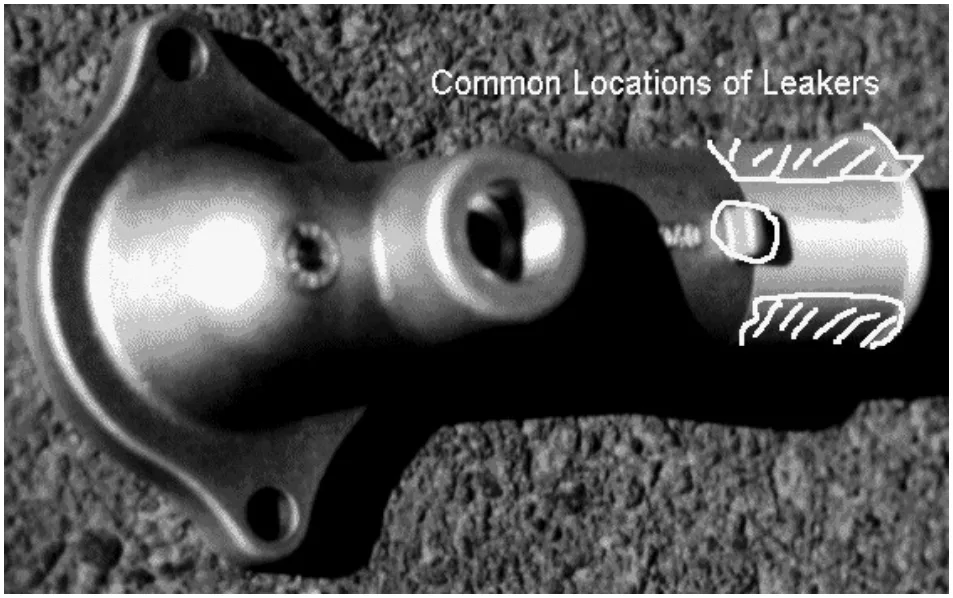
- 누설은 주로 튜브의 가공된 끝부분 또는 그 근처에서 발생했으며, 종종 파팅 라인 근처에서 발견됨. 일부 누설은 러그 바닥 근처에서 발견됨.
- 가공은 내부 기공을 노출시키는 주요 요인으로 식별됨.
- 튜브 내부 표면의 콜드 셧은 누설 발생과 강한 상관 관계를 보임 (Table 3.1). 이러한 콜드 셧은 내부 표면에서 다공성 주물 중심으로 이어지는 경로를 제공함.
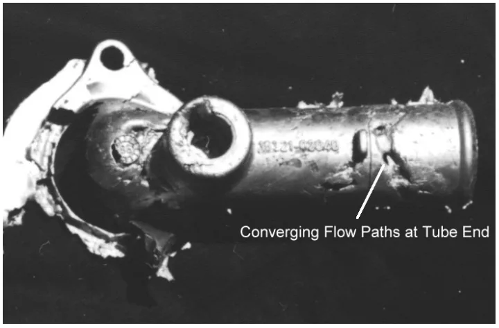
- 가공된 표면의 노출된 가스/수축 기공은 일반적이었지만, 누설과의 직접적인 연관성은 콜드 셧보다 덜 명확했음. 가스 혼입은 조기 샷 전환 및 발산형 탕도 설계 때문인 것으로 분석됨 (Figures 3.9, 3.10, 3.11).
- 실린더 내부 표면의 표면 기공(휘발성 이형제로 인한 것으로 추정)은 때때로 누설과 함께 관찰되었으며, 대개 콜드 셧과 함께 발생함.
- 러그 주변의 미세 균열(응고 응력 및 기타 결함과 관련됨)은 때때로 누설과 관련됨.
- 실험 결과 (제4장):
- 금형/용탕 온도의 영향: 금형 온도(오일 냉각 수준으로 제어)는 누설 형성에 상당한 영향을 미쳤음. 금형 냉각이 높을수록(금형 온도가 낮을수록) 누설 발생 확률이 높아짐 (Table 4.4, Table 4.5). 용탕 온도가 낮을수록 누설이 더 많이 발생하는 경향을 보였지만, 이 실험 내에서는 통계적으로 유의하지 않았음 (Table 4.6, Table 4.7).
- 누설률 예측:
- 오일 냉각 수준과 누설률 사이에 비선형 관계가 발견되었으며, 이는 회귀 분석을 사용하여 모델링할 수 있었음 (Equations 4.3, 4.4; Figures 4.4, 4.5).
- 측정된 금형 캐비티 온도(gate, fixed cavity, moving cavity, sliding core)는 누설 발생과 상관 관계를 보였으며, 결정 계수(R²)는 약 0.04에서 약 0.09 범위였음 (Table 4.10).
- 4개의 캐비티 내 온도와 사출 종료 시 플런저 변위를 사용한 다중 선형 회귀 모델은 누설 발생률을 합리적으로 예측했음 (Figures 4.9, 4.10).
- 금형의 열적 상태: 연구는 금형 온도 측정이 누설 예측 변수로 사용될 수 있을 만큼 금형의 열적 상태에 대한 충분한 정보를 제공한다는 것을 강조함. 슬라이딩 코어 온도는 오일 냉각 수준에 크게 영향을 받았음 (Figure 4.11). 평균 금형 온도는 용탕 온도에 의해 측정 가능하게 영향을 받았음 (Figure 4.12).
- 기타 변수: 사출 중 총 플런저 변위(주입된 용탕량 표시) 또한 누설 형성과 눈에 띄는 관계를 보였음. 평소보다 긴 변위(용탕량 적음)는 더 많은 누설과 상관 관계가 있었음.
그림 목록 (Figure Name List):
![Figure 2.10 Short Shots in Zinc and Aluminium Alloys Showing How Gas
Entrapment Can Occur in the Cavity. Shots A, B, and C Differ in the Amount of
Metal Ladled. [12]](https://castman.co.kr/wp-content/uploads/image-2366.webp)
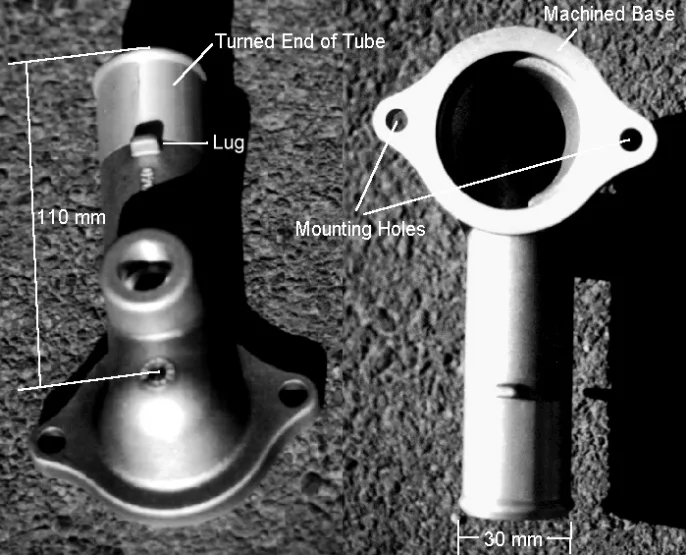
- Figure 1.1 Automotive Water Inlet Casting.
- Figure 1.2 Flow Chart of Part Manufacture.
- Figure 2.1 Fracture Along the Face of a Cold Flake.
- Figure 2.2 Mechanism of Cold Flake Formation.
- Figure 2.3 Heat Losses From Alloy During Casting Cycle.
- Figure 2.4 Flow Lines on Flat Plate Castings Showing Difference Between Casting Filled by Full Width of Fan Gate (a) and Casting Filled by Partially Blocked Gate (b).
- Figure 2.5 "Large Gate Pores … Exposed by Machining to Create a Leaker."
- Figure 2.6 Air Entrapment at too Low and too High a First Stage Velocity.
- Figure 2.7 Wave Formed at Critical First Stage Plunger Speed.
- Figure 2.8 Optimum Acceleration Profiles For Different Shot Fill Ratios.
- Figure 2.9 Air Entrapment in a Poorly Designed Runner.
- Figure 2.10 Short Shots Showing How Gas Entrapment Can Occur in the Cavity.
- Figure 2.11 Typical Inclusions in Die Cast Aluminium Alloys.
- Figure 2.12 Tendency for Sludge Formation as a Function of Temperature and Sludge Factor.
- Figure 2.13 Interdendritic Shrinkage in Sand Cast Gun Metal Casting.
- Figure 2.14 Solidification Shrinkage in Aluminium Silicon Alloys.
- Figure 2.15 Shrinkage Porosity Distributions at Different Alloy Compositions.
- Figure 2.16 Shrinkage Feeding Using Directional Solidification.
- Figure 2.17 Surface Cracking in a Zinc Casting.
- Figure 2.18 Fault Tree Summarising the Major Causes of Leakers.
- Figure 3.1 Photograph of Water Inlet Casting Showing Common Sites of Leakers.
- Figure 3.2 Likely Porosity Distribution at Tube End, Showing Effect of Overflows and Machining.
- Figure 3.3 Water Inlet Die Cavity Showing Location of Overflows.
- Figure 3.4 Short Shot Showing Last Areas to Fill.
- Figure 3.5 Restrained Sections Near Tube End.
- Figure 3.6 Cold Shut at Surface of Leaking Casting Leading to Porous Inner Region.
- Figure 3.7 Large Cold Shut Leaving Void Through Casting Centre.
- Figure 3.8 Extensive Gas Porosity Found Through Section of Tube End.
- Figure 3.9 Diverging Runner Section of Water Inlet Casting.
- Figure 3.10 Shot Timing for Water Inlet Casting.
- Figure 3.11 Short Shot Showing Flow Through Runner.
- Figure 3.12 Surface Porosity on Internal Face of Tube.
- Figure 3.13 Section Through Surface Porosity on Internal Face of Tube Leading to Interconnected Pores Within the Casting.
- Figure 3.14 Section Through Surface Porosity on Internal Face of Tube that Appears to be Isolated from Porosity Within the Casting.
- Figure 3.15 Drag Marks on Internal Wall of Tube.
- Figure 3.16 Small Crack Running Through Casting Near Base of Lug.
- Figure 3.17 Cracks Associated With Large Gas Pores Near Base of Lug.
- Figure 4.1 Diagram of Cooling Line Set-up During Trial.
- Figure 4.2 Summary of Experimental Design and Expected Effects.
- Figure 4.3 Locations of Temperature Measurements in Cavity.
- Figure 4.4 Plot of Predicted Leaker Rate, Using Equation 4.3, Versus Shot Number.
- Figure 4.5 Plot of Predicted Leaker Rate, Using Equation 4.4, Versus Shot Number.
- Figure 4.6 Plot of the Value of Linear Regression Based on Measured Metal Temperature Versus Trial Shot Number.
- Figure 4.7 Plot of the Value of Linear Regression Based on Sliding Core Temperature Versus Trial Shot Number
- Figure 4.8 Plot of the Value of Linear Regression Based on Moving Cavity Temperature Versus Trial Shot Number
- Figure 4.9 Prediction of Leakers Using Multiple Linear Regression.
- Figure 4.10 Average Values of Multiple Linear Regression.
- Figure 4.11 Relationship Between Casting Cavity Core Temperature and Oil Cooling Level.
- Figure 4.12 Effect of Metal Temperature on Average Die Temperature.
- Figure 5.1 Cross Section Through Tube Wall Showing Cold Shuts, Internal Porosity, and Material Removal Combining to Provide a Path for Leakage.
- Figure A.1 Full Shot Trace for Water Inlet Casting.
- Figure A.2 Close Ups of Cavity Filling Period of Three Shot Traces.
- Figure A.3 Water Inlet Casting With Runners and Overflows.
- Figure A.4 Area of Casting Obscured by Support During Pressure Testing.
- Figure B.1 Enlarged Shot Trace for Water Inlet Casting.
- Figure C.1 Optimum Shot Profile for Water Inlet Casting.
- Figure C.2 Actual Shot Profile for Water Inlet Casting.
- Figure D.1 Level 0 (No Cold Shuts)
- Figure D.2 Level 1 (Small Cold Shuts)
- Figure D.3 Level 2 (Moderate Cold Shuts)
- Figure D.4 Level 3 (Extensive Cold Shuts)
- Figure D.5 Level 4 (Severe Cold Shuts)
7. 결론:
본 연구에서 제시된 정보로부터 여러 중요한 결론을 도출할 수 있습니다.
- 누설 발생을 분석할 때, 주물은 표면 영역과 주물 중심으로 나눌 수 있습니다. 이 모든 영역은 누설이 발생하기 위한 누설 경로를 포함해야 합니다. 그런 다음 누설 결함의 진단 및 감소를 위한 논리적 절차가 존재합니다.
- 주조 합금에서 금형으로의 열전달률은 워터 인렛 주물의 콜드 셧 발생에 결정적인 영향을 미칩니다.
- 주물 표면의 콜드 셧은 워터 인렛 주물의 누설 발생과 강한 연관성이 있습니다.
- 중요한 주조 입력 상태 분석을 통해 주요 주조 결과를 예측할 수 있는 능력이 입증되었습니다. 이는 고압 다이캐스팅 공정 모니터링을 통해 이러한 주요 주조 결과의 발생을 생산에서 예측하고 제어할 수 있음을 나타냅니다.
8. 참고 문헌:
- [1] LaVelle, ‘Aluminium Die Casting and Factors Affecting Pressure Tightness’, Transactions of the American Foundrymen's Society, Volume 70, 1962.
- [2] Walkington, ‘Short Course on Analysis of Die Casting Defects’, Cooperative Research Centre for Alloy and Solidification Technology, 1995.
- [3] Holz, ‘Trouble-Shooting Aluminium Die Casting Quality Problems’, 7th International Die Casting Congress, 1972.
- [4] Murray, ‘Defects in Pressure Die Castings as Pertaining to Low Gas Pressure Applications’, CSIRO Consultation Report 90/M/101, Commonwealth Scientific and Industrial Research Organisation, 1990.
- [5] Harding, Bennet, and Robinson, ‘Production of Aluminium Die Castings Using a Fan Gate [3] Some Factors Affecting Conditions at the Orifice’, 8th SDCE International Die Casting Exposition and Congress, 1975.
- [6] Iwahori, Nakamura, Tozawa, and Yamamoto, ‘Metal Flowing Behavior in Die Castings and Defects in Aluminium Die Castings’, 13th SDCE International Die Casting Congress and Exposition, 1985.
- [7] Murray, Chadwick, and Ghomashchi, ‘Aluminium Alloy Solidification in High Pressure Die Castings’, Materials Australasia, June 1990.
- [8] Murray, ‘Shot Sleeves, a Quality Control’, Die Casting Bulletin, April 1996.
- [9] Herman, ‘Die Casting Technology - Calculations’, Die Casting Education Project RMIT University, 1995.
- [10] Davis and Robinson, ‘Production of Aluminium Die Castings Using a Fan Gate [2] The Effect of Casting Conditions at the Gate on Casting Quality’, 8th SDCE International Die Casting Exposition and Congress, 1975.
- [11] Editor of the Die Casting Engineer, ‘Eliminating Surface Defects on Zinc Die Castings’, Die Casting Engineer, January/February 1977.
- [12] Stuhrke and Wallace, ‘Gating of Die Castings’, Transactions of the American Foundrymen’s Society, Volume 73, 1966.
- [13] Neff, ‘Principles of Molten Metal Processing for Improving Die Cast Quality’, 16th NADCA Congress and Exposition, 1991.
- [14] Titone, ‘Important Considerations in the Trimming of Die Castings’, 5th SDCE National Die Casting Congress, 1968.
- [15] Johnson, Bishop, and Pellini, ‘Application of Chills to Improving Pressure Tightness of Gun Metal (88-8-4)’, Transactions of the American Foundrymen's Society, Volume 62, 1954.
- [16] Veinik, ‘Thermodynamic Factors in Metal Injection: Effect of Friction on Gas Content and Quality’, 4th SDCE National Die Casting Exposition and Congress, 1966.
- [17] Garber, ‘Theoretical Analysis and Experimental Observation of Air Entrapment during Cold Chamber Filling’, Die Casting Engineer, May/June 1982.
- [18] Thome and Brevick, ‘Optimal Slow Shot Velocity Profiles For Cold Chamber Die Casting’, 18th NADCA Congress, 1995.
- [19] Luis-Martin and Robla, ‘Evaluation of Gas Porosity in Zinc Die Castings’, 12th SDCE International Die Casting Congress and Exposition, 1983.
- [20] Miller, ‘Inclusion Control of Die Casting Alloys’, Die Casting Engineer, September/October 1984.
- [21] Shivkumar, Apelian, and Brucher, ‘Melt Cleanliness in Die Cast Aluminium Alloys’, 16th NADCA Congress and Exposition, 1991.
- [22] Anderson, ‘Shot Peening to Reduce Porosity in Die Castings’, Modern Metals, Volume 9 Number 1, 1953.
- [23] DePue and Pennington, ‘Influence of Silicon on Gun Metal Alloys’, Transactions of the American Foundrymen's Society, Volume 70, 1962.
- [24] Gordon, Meszaros, Naizer, and Mobley, ‘Equations for Predicting the Percent Porosity in Die Castings’, 17th NADCA Congress, 1993.
- [25] Garber and Draper, ‘Shrinkage in #380A Aluminium Alloy’, Die Casting Engineer, November/December 1979.
- [26] Otte, ‘Castability of Aluminium Alloy 380’, Report for the Cooperative Research Centre for Alloy and Solidification Technology, 1997.
- [27] Taylor, ‘The Role of Iron and Other Elements in the Formation of Porosity in Al-Si-Cu Alloy Castings’, Department of Mining, Minerals, and Materials Engineering, University of Queensland, 1997.
- [28] Kalghatgi, ‘Effect of Silicon Content on Porosity in Aluminium Die Castings with More than 1/4-in. Wall Thickness’, 14th SDCE International Die Casting Congress and Exposition, 1987.
- [29] Herman, ‘Die Casting Technology - Die Casting Process and Die Design Level II’, Die Casting Education Project RMIT University, 1997.
- [30] Kulunk, Shabestari, Gruzleski, and Zuliani, ‘Beneficial Effects of Strontium on A380 Alloy’, Transactions of the American Foundrymen's Society, 1996.
- [31] Sugiyama, Yonekura, and Ookouchi, ‘Transferred Pressure and Casting Qualities of Aluminium Diecasting’, Diecasting World, September 1996.
- [32] Arnberg, Dahle, Paradies, and Syvertsen, ‘Factors Affecting the Castability of Aluminium Foundry Alloys’, International Conference on Casting and Solidification of Light Alloys, August 1995.
- [33] Garber and Draper, ‘The Effects of Process Variables on the Internal Quality of Aluminium Die Castings’, 10th SDCE International Die Casting Exposition and Congress, 1979.
- [34] Micks and Zabek, ‘Identifying Some Common Problems With Aluminium Castings’, Transactions of the American Foundrymen’s Society, Volume 81, 1973.
- [35] Chu, Cheng, and Shivpuri, ‘Soldering Phenomenon in Aluminum Die Casting: Possible Causes and Cures’, 17th NADCA Congress, 1993.
- [36] ‘Engineering Design, (12.7 Fault Tree Analysis)’, Text, GET DETAILS FROM NICK
- [37] ASM International, ‘Metals Handbook - Volume 2, Properties and Selection: Nonferrous Alloys and Special-Purpose Materials’, 10th Edition, ASM International, 1990.
- [38] ASM International, ‘Metals Handbook - Volume 9, Metallography and Microstructure’, 9th Edition, ASM International, 1985.
- [39] Walpole and Myers, ‘Probability and Statistics for Engineers and Scientists’, Fifth Edition, Macmillan Publishing Company, 1993.
- [40] Ball and Buckwell, ‘Work out Statistics “A” Level’, Macmillan Education Ltd., 1986.
- [41] Moroney, ‘Facts from Figures’, Second Edition, Penguin Books Ltd., 1957.
- [A1] Buhler, ‘Operating Manual for Buhler H250B-P Horizontal Cold Chamber Die Casting Machine’, Buhler. (Referenced in Appendix A)
- [B1] Herman, ‘Die Casting Technology - Calculations’, Die Casting Education Project RMIT University, 1995. (Referenced in Appendix B)
- [B2] Iwahori, Nakamura, Tozawa, Yamamoto, ‘Metal Flowing Behavior in Die Castings and Defects in Aluminium Die Castings’, 13th SDCE International Die Casting Congress and Exposition, 1985. (Referenced in Appendix B)
- [B3] ASM International, ‘Metals Handbook - Volume 2, Properties and Selection: Nonferrous Alloys and Special-Purpose Materials, 10th Edition’, ASM International, 1990. (Referenced in Appendix B)
- [C1] ASM International, ‘Metals Handbook - Volume 2, Properties and Selection: Nonferrous Alloys and Special-Purpose Materials, 10th Edition’, ASM International, 1990. (Referenced in Appendix C)
- [C2] Herman, ‘Die Casting Technology - Calculations’, Die Casting Education Project RMIT University, 1995. (Referenced in Appendix C)
- [E1] Walpole and Myers, ‘Probability and Statistics for Engineers and Scientists’, Fifth Edition, Macmillan Publishing Company, 1993. (Referenced in Appendix E)
- [E2] Moroney, ‘Facts from Figures’, Second Edition, Penguin Books Ltd., 1957. (Referenced in Appendix E)
9. 저작권:
- 본 자료는 "Stephen Thompson"의 논문입니다. "Mechanisms of Leaker Formation in Aluminium High Pressure Die Casting"을 기반으로 합니다.
- 논문 출처: 10.13140/RG.2.2.25896.08963
본 자료는 위 논문을 바탕으로 요약되었으며, 상업적 목적의 무단 사용을 금합니다.
Copyright © 2025 CASTMAN. All rights reserved.