この紹介文書は、「Proceedings of the 3rd Congress for Intelligent Combining of Design, Casting, Computer Simulation, Checking and Cyclic Behaviour for Efficient Cast Components, March 5th-6th, 2025, Darmstadt (InCeight Casting C⁸)」によって発行された「Fatigue assessment of hot-chamber zinc die-casting components in relation to the casting process and casting process simulation」論文に基づいています。
1. 概要:
- タイトル: Fatigue assessment of hot-chamber zinc die-casting components in relation to the casting process and casting process simulation
- 著者: Christian Pittel, Axel Kansy, Christos Mangos, Saliha Gündogan
- 発行年: 2025
- 発行学術誌/学会: Proceedings of the 3rd Congress for Intelligent Combining of Design, Casting, Computer Simulation, Checking and Cyclic Behaviour for Efficient Cast Components, March 5th-6th, 2025, Darmstadt (InCeight Casting C⁸)
- キーワード: die casting, hot chamber, zinc, Z410, casting parameters, casting process simulation, cyclic material behavior.
2. 抄録:
亜鉛ダイカスト合金は、その高い強度と表面品質により、静的または低サイクル用途で多くの産業で使用されています。熱間チャンバーダイカストプロセスは一般的に非常に短いサイクルタイムを持ち、高い生産性と密接に関連しています。アルミニウムと比較して、亜鉛ダイカスト合金は融点が低く、ほぼ最終形状(「near net shape」)の表面と高い寸法精度を維持しながら、著しく薄い壁厚で鋳造できます。これにより、プロセスにおけるエネルギー消費が削減され、金型寿命が延び、全体的なCO2換算排出量の削減に貢献します。
しかし、亜鉛ダイカスト合金は、これらの材料の周期的挙動を記述するための疲労データおよび疲労評価方法が不足しているため、高サイクル荷重下で使用されることは稀です。これまでのところ、特に鋳造パラメータによってサンプルが影響を受ける場合の周期的材料挙動に関する科学的研究は行われていません。疲労評価コンセプトの基礎を提供するために、Z410で作られたサンプルの周期的材料挙動を調査し、局所的な微細構造と相関させました。設計コンセプトは、周期的解析からのデータと、鋳造プロセス中のプロセスパラメータ、局所的な条件、鋳造プロセスによって引き起こされる凝固効果、および微細構造とを関連付けることによって導き出されました。
疲労評価コンセプトを検証するために、金型温度とゲート速度に変化を持たせて部品を鋳造しました。さらに、追加因子として流動長さの影響を考慮するために、金型内の異なる位置からの部品を選択しました。鋳造部品の疲労強度を決定するために、応力制御疲労試験を実施しました。結論として、決定された部品の疲労強度を、疲労評価コンセプトを用いて推定された許容荷重と比較しました。
3. 序論:
亜鉛ダイカスト合金[1]は、その高い表面品質と部品品質により、準静的または低サイクル用途の多くの産業分野で使用されています。熱間チャンバーダイカストプロセスは、その非常に短いサイクルタイムと高い生産性により特に重要です。亜鉛ダイカスト合金を例えばアルミニウムと比較すると、低い融点と、同時に高い表面品質および寸法精度を備えた著しく薄肉の鋳造の可能性は特に注目に値します。これにより、プロセスにおけるエネルギー消費が低減され、金型寿命が延び、CO2排出量の削減に貢献します。この論文は、亜鉛ダイカスト合金、具体的にはZ410合金の疲労挙動を、様々な鋳造プロセスパラメータ下で調査することを目的としています。
しかし、亜鉛ダイカスト合金は、材料の周期的挙動を記述するためのデータおよび設計方法が不足しているため、高サイクル応力を受ける部品にはほとんど使用されていません。特に微細構造とプロセスパラメータを考慮した周期的材料挙動を記述する利用可能な結果はありません。文献[2, 3, 4, 5]に見られる調査では、試験手順と使用された評価方法の文書化において十分な詳細が提供されていません。FKMガイドライン[6]などの一般的な設計ガイドラインには、亜鉛ダイカストに関するパラメータは含まれていません。さらに、このようなガイドラインは通常、材料の引張強度に基づいています。
このアプローチは、部品から引張強度を決定できず、したがって結果の転移性が保証されないため、亜鉛ダイカストには適していません。疲労データと評価方法における特定されたギャップに対処するために、次のセクションでは、Z410合金の周期的材料挙動を評価するために実施された実験計画の概要を説明します。
4. 研究概要:
研究テーマの背景:
熱間チャンバーダイカストで加工された亜鉛ダイカスト合金、特にZ410は、高い強度、表面品質、生産性、薄肉鋳造能力、寸法精度、低エネルギー消費、長い金型寿命など、アルミニウムと比較して利点を提供します。これらの利点はCO2排出量の削減に貢献します。
先行研究の状況:
これらの利点にもかかわらず、亜鉛ダイカスト合金は高サイクル荷重を受ける部品にはほとんど使用されていません。特に微細構造と鋳造プロセスパラメータの影響を考慮した疲労データと確立された疲労評価方法論が著しく不足しています。既存の文献[2, 3, 4, 5]は、試験手順と評価方法に関する十分な詳細を提供していません。FKMガイドライン[6]のような標準的な設計ガイドラインには、亜鉛ダイカストに関するパラメータが含まれておらず、部品の引張強度を決定することの難しさと結果の転移性を保証することの問題のため、引張強度に基づく従来のアプローチは不適切です。
研究目的:
主な目的は、Z410熱間チャンバーダイカスト部品に適用可能な疲労評価コンセプトの基礎を確立することでした。これには、周期的材料挙動を調査し、それを局所的な微細構造と相関させ、設計コンセプトを開発することが含まれていました。このコンセプトは、周期的材料データを鋳造プロセスパラメータ、局所的な鋳造条件、凝固効果、および結果として生じる微細構造と関連付けることを目指しています。さらなる目標は、様々な鋳造条件下での部品試験を通じてこの疲労評価コンセプトを検証することでした。
核心研究:
研究の核心は、包括的な実験的および数値的調査を含んでいました:
- 材料特性評価: Z410合金の周期的材料挙動を、様々な条件下(壁厚、金型温度、ゲート速度)でノッチなしおよびノッチ付き試験片を使用して決定しました。微細構造は、鋳造プロセスシミュレーション(MAGMASOFT®)および金属組織学的分析を使用して評価しました。比較のために準静的引張試験を実施しました。
- 疲労試験: 試験片(ニアネットシェイプおよびプレートから機械加工)および検証部品(亜鉛ダイカストカップリングプレート)に対して、ひずみ制御(低サイクル疲労 - LCF)および応力制御(高サイクル疲労 - HCF)試験の両方を実施しました。異なる応力比(R = -1、R = 0)を使用しました。
- プロセスシミュレーション: MAGMASOFT®を使用して凝固および金型充填シミュレーションを実施し、プロセスパラメータ(金型温度、ゲート速度、壁厚、Frech Dosing System - FDS)が充填終了時の溶湯温度および冷却速度に及ぼす影響を分析しました。
- 疲労評価コンセプト開発: 以下を組み込んだコンセプトを開発しました:
- 平均応力の影響を考慮するためのP_RAM損傷パラメータ。
- 高応力体積(HSV_90%)に基づく統計的サイズ効果。
- 応力勾配(G_σ)およびワイブル係数(k_st)から導出されたサポートファクター(n_st)によって定量化された幾何学的サイズ効果(ノッチ効果)。
- 多重線形回帰を使用して鋳造シミュレーションパラメータ(充填終了時の温度、冷却速度)から導出された係数K_CSによって表される技術的サイズ効果および表面状態の影響。
- f_2.5%係数を使用した生存確率の考慮。
- 検証: 開発された疲労評価コンセプトは、異なる鋳造条件(金型温度、FDS使用、キャビティ位置)下で実施された部品試験からの実験結果と予測された疲労寿命/強度を比較することによって検証されました。
5. 研究方法論
研究設計:
本研究では、実験的および数値的研究設計を組み合わせて採用しました。実験計画法(DoE)アプローチが研究を導き、試験片レベルの特性評価と部品レベルの検証の両方について、主要な鋳造プロセスパラメータ(壁厚、金型温度、ゲート速度、Frech Dosing System(FDS)の使用、金型キャビティ位置)を体系的に変化させました。中心的な方法論は、Z410の周期的材料特性を決定し、これらを微細構造およびプロセスシミュレーション結果と相関させ、多パラメータ疲労評価コンセプトを開発し、このコンセプトを部品疲労試験に対して検証することを含んでいました。
データ収集および分析方法:
- 材料製造: 試験片および部品は、Frech DAW125E熱間チャンバーダイカスト機を使用して製造されました。
- 機械的試験:
- 疲労試験:HCF領域(N > 5・10⁴サイクル、N_G = 10⁷サイクル)について、電気共振試験機(F_max = 5 kN、f = 56-81 Hz)で応力制御試験(R=-1、R=0)を実施。LCF領域および周期的応力-ひずみ曲線決定のために、サーボ油圧試験機(F_max = 25 kN、f = 0.1-25.0 Hz)でひずみ制御試験を実施。S-N曲線評価には最尤法[10]を使用。
- 準静的試験:Schenck RSA 100機で[9]に従った引張試験を実施。
- ひずみ測定:部品の実験的ひずみ分析のためにひずみゲージを使用。
- シミュレーション:
- 鋳造プロセス:様々なプロセス条件下での充填終了時温度および冷却速度を決定するために、MAGMASOFT®ソフトウェアを使用した凝固および金型充填シミュレーションを実施。
- FE解析:試験片および部品の設計関連パラメータ(ノッチ係数K_t、高応力体積HSV_90%、応力勾配G_σ)の計算に使用。部品応力決定のための線形弾性解析。Neuber[26]およびMasing[27]修正を使用した局所弾塑性荷重の解析的決定。
- 微細構造分析: 微細構造文書化および破面分析のための金属組織学的断面および走査型電子顕微鏡(SEM)を使用。
- 疲労評価モデリング: 平均応力に対するP_RAM損傷パラメータ[17, 18, 19]。HSV_90%およびワイブル係数k_st[6, 19, 23, 24]に基づく統計的サイズ効果(n_st)。シミュレーション出力(充填終了時温度、冷却速度)と疲労強度低下を相関させる多重線形回帰によって導出された技術的サイズ/表面係数(K_CS)。散布帯[19, 25]に基づく生存確率係数f_2.5%。
研究トピックおよび範囲:
本研究は、熱間チャンバーダイカストされた亜鉛合金Z410部品の疲労挙動に焦点を当てました。主なトピックは以下の通りです:
- 周期的材料特性(LCF、HCF、平均応力の影響)の定量化。
- 疲労挙動と局所微細構造および鋳造プロセスパラメータ(金型温度、ゲート速度、壁厚、FDS、キャビティ位置)との相関。
- 表面近傍欠陥(例:コールドシャット)および微細構造変動(冷却速度による)が疲労強度に及ぼす影響。
- 統計的、幾何学的、および技術的サイズ効果、表面状態、および生存確率を組み込んだ疲労評価コンセプトの開発。
- 疲労に関連するパラメータ(温度、冷却速度)を予測し、それらを評価コンセプトに統合するための鋳造プロセスシミュレーション(MAGMASOFT®)の使用。
- 汎用ダイカスト部品(カップリングプレート)を使用した評価コンセプトの検証。
範囲は、Z410合金、試験された特定の試験片および部品形状、および調査された鋳造パラメータの範囲に限定されました。
6. 主要結果:
主要結果:
- 最大1.5 mmの壁厚に対して、フライス加工されたエッジを持つニアネットシェイプZ410試験片のベースライン疲労寿命曲線(P_RAM – N曲線)が確立されました(Fig. 20)。3.0 mm厚の試験片は、HCF領域で著しく低い疲労強度を示しました。
- 平均応力の影響はP_RAMパラメータを使用して定量化され、Z410の平均応力感度係数M_a = 0.41が得られました(セクション6.1)。
- Z410は高強度鋼に匹敵する高いノッチ感度を示し、決定されたワイブル係数はk_st = 39.2でした(Fig. 21-A、セクション6.2)。サポート効果は応力勾配に強い依存性を示しました(Fig. 21-B)。
- 鋳造シミュレーション結果(充填終了時の温度、冷却速度)に基づいて技術的サイズ効果と表面状態の影響を定量化するために、多重線形回帰(R² = 0.64)を使用してパラメータK_CSが開発されました。充填終了時の温度が疲労強度低下に最も大きな影響を与えました(Fig. 23、Fig. 24、セクション6.3)。
- 50%から97.5%の生存確率に変換するために、ベースライン散布帯から生存確率係数f_2.5% = 0.85(T_σ = 1:1.23に対応)が決定されました(セクション6.4)。
- Z410ダイカストの場合、準静的引張強度と伸びは疲労強度との相関が低いことが示されました(Fig. 18)。最小伸び要件は満たされましたが、引張強度値は標準最小値[1]を下回りました。
- 金属組織学的およびSEM分析により、表面近傍欠陥(微細構造的分離、気孔、潜在的なコールドシャット)が、特に試験片エッジでの亀裂開始において、疲労挙動に著しく影響することが確認されました(Fig. 14、Fig. 15)。これらの欠陥は、金型温度や壁厚(冷却速度)などの鋳造パラメータに関連しています。
- Frech Dosing System(FDS)は、試験条件下で従来の鋳造と比較して、部品の気孔率およびシミュレーションされた温度/冷却速度に最小限の影響しか与えませんでした(Fig. 10-13、Fig. 16)。
- カップリングプレート部品での検証試験では、異なる鋳造バリエーション(CT-01からCT-04)にわたって一貫した実験的疲労強度が得られました。しかし、開発された疲労評価コンセプトは保守的な推定値を提供しました(N=10⁷、P_S=50%で予測90 MPa対実験129 MPa)(Fig. 28)。この不一致は、一部には鋳造シミュレーションパラメータの不確実性、および欠陥サイズと比較して部品の高応力体積(HSV_90%)が小さいことによる可能性があります。
図リスト:
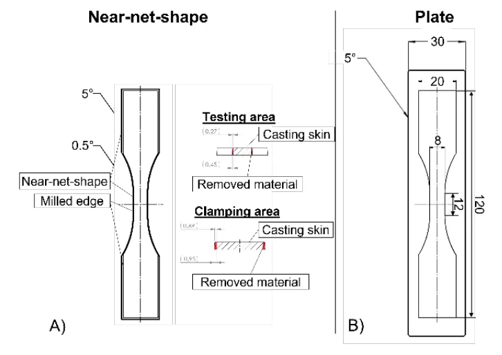
- Fig. 1 Unnotched specimens with three different manufacturing routes; A) Near-net-shape and near-net-shape with milled edges; B) Cast plate with milled edges.
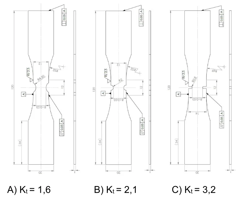
- Fig. 2 Notched specimens with 3 different notch factors.
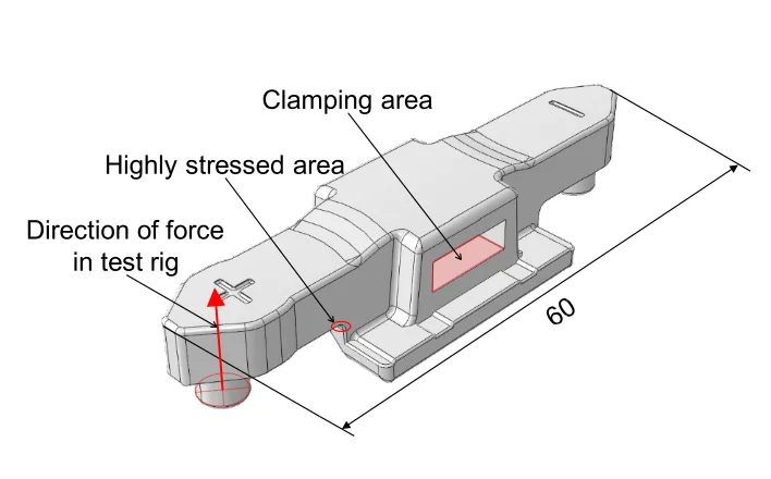
- Fig. 3 Geometry of the component for validation and schematic representation of forces and boundary conditions of the test rig
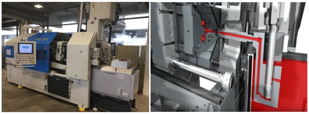
- Fig. 4 Frech DAW125E hot chamber die casting machine at Aalen University (left); Schematic layout of a Frech hotchamber machine during the filling process (right). The flow of the melt is marked in red [
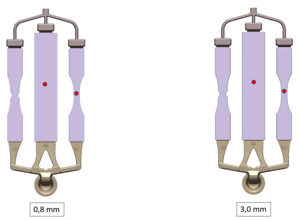
- Fig. 5 Overview of the test samples with sprue and overflow system 0.8 mm wall thickness (left) 3.0 mm wall thickness (right). The red points mark the measuring points at which the values for the cooling rate and the temperature at the end of the mold filling were taken from.
- Fig. 6 Temperature at the end of mold filling with 0.8 mm wall thickness(left) and with 3.0 mm wall thickness (right).
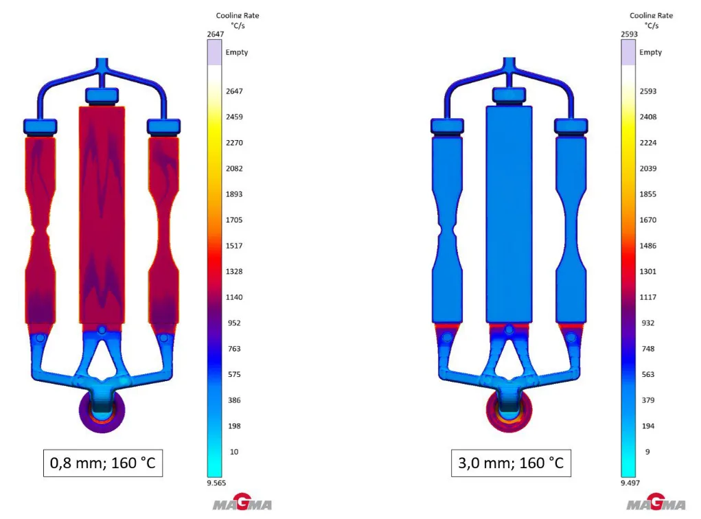
- Fig. 7 Cooling rate with 0.8 mm wall thickness (left) compared to the cooling rate with 3.0 mm wall thickness (right).
- Fig. 8 Conventional pouring process (left) compared to the Frech Dosing System (FDS) (right).
- Fig. 9 Conventional casting process (left) compared to the Frech Dosing System (FDS) (right). The red dots mark the measuring point at which the values for the cooling rate and the temperature at the end of the mold filling were taken from.
- Fig. 10 Temperature at the end of mold filling with the conventional pouring process (left) and with FDS (right).
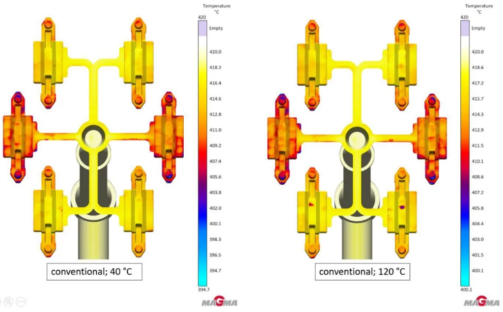
- Fig. 11 Temperature at the end of mold filling conventional at 40 °C mold temperature (left) and at 120 °C mold temperature (right).
- Fig. 12 Cooling rate at 40 °C flow temperature in the mold with the conventional pouring process (left) and with FDS (right).
- Fig. 13 Cooling rate for conventional condition at 40°C mold temperature (left) at 120°C mold temperature (right).
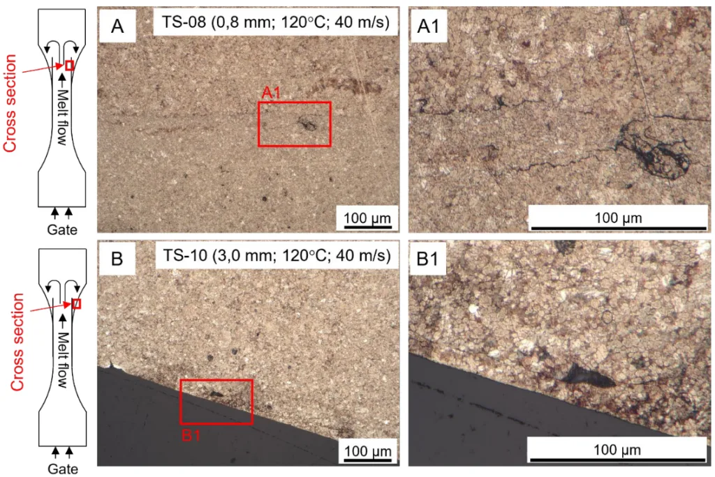
- Fig. 14 Metallographic micrograph in the transition area of 2 representative specimens.
- Fig. 15 SEM image of two specimen fractured in the transition area remote from the gate
- Fig. 16 Metallographic micrograph of the components from CT-01 and CT-03.
- Fig. 17 Metallographic micrograph of the components in the area of the stress hot spot.
- Fig. 18 Results of the tensile tests compared to the fatigue strength of the test series TS-08 to TS-17.
- Fig. 19 Test rigs for the cyclical investigations; A) Electric test-rig for stress-controlled fatigue tests; B) servo-hydraulic test-rig for strain-controlled fatigue tests
- Fig. 20 Baseline P_RAM − N curve of near-net-shaped specimens with milled edges.
- Fig. 21 Investigation regarding influence of the notch factor on fatigue strength.
- Fig. 22 Investigation regarding influence of casting parameters on fatigue strength.
- Fig. 23 Comparison of the casting parameters derived from casting process simulation to the fatigue strength.
- Fig. 24 Comparison of the casting parameters derived from the casting process simulation to the reduction of fatigue strength due to the surface condition.
- Fig. 25 Transformation of the elastic load to elastic-plastic stresses and strains.
- Fig. 26 A) Test rig for component fatigue test; B) Model for the FEM simulation (Visualization with 50x deformation); C) Loading results from the FEM simulation; D) Results of the experimental strain analysis.
- Fig. 27 Design P_RAM − N curve for the component derived from the baseline P_RAM − N curve using the fatigue factors for transferability.
- Fig. 28 Comparison of the design P_RAM − N curve with the experimental results of the component fatigue tests.
7. 結論:
[28]は、金型温度、破断伸び、および壁厚の関数としての引張強度を記述しています。この相関関係は、準静的強度特性に対して部分的に再現できます。しかし、疲労強度については、金型温度に応じて反対の挙動が見られます。特に、溶融物の熱容量が小さく、冷却速度が高い薄肉試験片(0.8 mm)の場合、これによりコールドシャットが発生し、表面近傍の欠陥を伴う表面状態の低下が生じる可能性があります。この効果は、鋳造プロセスシミュレーションからの鋳造パラメータ「充填終了時の温度」と「冷却速度」の組み合わせによって特徴付けられるようです。金属組織学的調査の結果は、サイクル荷重下での試験片の疲労挙動が主に表面近傍の欠陥と表面層の微細構造によって決定されるという仮定を裏付けています。この論文は、亜鉛ダイカスト合金の疲労挙動に影響を与える鋳造パラメータ、特に充填終了時の温度と冷却速度の重要な役割を強調しています。調査結果は、これらのパラメータを最適化することで、高応力用途で使用される部品の疲労性能を大幅に向上させることができることを示唆しています。
表面状態を考慮するためのパラメータの導入により、試験片の疲労強度の低下を表すことができました。しかし、個々の試験シリーズから部品への転移性は、ある程度までしか機能しませんでした。
鋳造プロセスシミュレーションからのパラメータの違いにもかかわらず、部品の周期的調査では疲労強度に有意な変動は見られませんでした。これに対する説明は、欠陥サイズと比較して部品のHSV_90%が小さいことにある可能性があり、これは既存の欠陥がHSV_90%の領域に見つからない可能性があることを意味します。さらに、鋳造プロセスシミュレーションパラメータの違いは、実際の鋳造プロセスでの測定によって検証されていないため、これらのパラメータにはかなり大きな不確実性があります。それにもかかわらず、サポート効果や散布帯など、亜鉛ダイカスト合金の設計に関連するパラメータを開発することは可能でした。これにより、亜鉛ダイカスト部品の設計者や鋳造所は、そのような部品の疲労強度について信頼性の高い推定を行うことができます。今後の研究は、亜鉛ダイカスト部品の疲労特性をさらに調査し、提案された疲労評価コンセプトを改良することに焦点を当てるべきであり、同時に業界向けの標準化されたガイドラインを確立する必要があります。
8. 参考文献:
- [1] DIN EN 12844:1998: Zink und Zink-Legierungen – Gussstücke – Spezifikationen; Deutsche Fassung.
- [2] Goodwin, F. E.; Ponikvar, A. L.: Engineering Properties of Zinc Alloys, International Lead Zinc Research Organization, 3rd edition, 1988.
- [3] Szczotka, S.; Klein, F.: Wechselfestigkeitseigenschaften von Zinkdruckgusslegierungen, 1991.
- [4] Goodwin, F. E.; Gagné, M.: Recent Developments in Impact, Flexural and Fatigue Data for Zinc Die Casting Anti-Theft Applications, SAE Technical Paper 2011-01-1088, 2011.
- [5] Leis, W.; Kallien, L. H.: Alterungsvorgänge bei Zinkdruckgusslegierungen, Gießerei 98, 07, S. 26–38, 2011.
- [6] FKM-Richtlinie – Rechnerischer Festigkeitsnachweis für Maschinenbauteile aus Stahl, Eisenguss- und Aluminiumwerkstoffen, 7. Auflage 2020, Forschungskuratorium Maschinenbau (FKM), Frankfurt am Main, 2020.
- [7] Kloos, K.-H.: Einfluss des Oberflächenzustandes und der Probengröße auf die Schwingfestigkeitseigenschaften, VDI-Berichte, 268, Darmstadt, VDI, 63-76, 1976.
- [8] Frech Warmkammer. [Youtube]. Oskar Frech GmbH + Co. KG, 2016; https://www.youtube.com/watch?v=p9uFyI N2fiE.
- [9] DIN EN ISO 6892-1:2019: Metallic materials – Tensile testing – Part 1: Method of test at room temperature; English version EN ISO 68921:2019.
- [10] Störzel, K.; Baumgartner, J.: Statistical Evaluation of Fatigue Tests Using Maximum Likelihood, Materials Testing, De Gruyter, 63 (2021) No. 8, 2021.
- [11] Testing and Documentation Guideline for the Experimental Determination of Mechanical Properties of Steel Sheets for CAE-Calculations, SEP 1240:2006-07, Jul. 2006 [Online]. Available: https://www.beuth.de/en/technical-rule/sep-1240/102501063.
- [12] Coffin, L. A.: A study of the effects of cyclic thermal stresses on a ductile metal, Trans. ASME, vol. 76, no.6, 1954, pp. 931 – 950, DOI: https://doi.org/10.1115/1.4015020.
- [13] Manson, S. S.: Fatigue: A complex subject – some simple approximations, Experimental Mechanics, vol. 5, no. 4, 1965, pp. 193 – 226, 1965, DOI: https://doi.org/10.1007/BF02321056.
- [14] Basquin, O. H.: The exponential law of endurance tests, in Materials Proceedings, no. 10, American Society Test, 1910, p. 625 – 630.
- [15] Morrow, J. D.: Cyclic plastic strain energy and fatigue of metals, American Society for Testing and Materials, ASTM STP 378, 1965, pp. 45 – 87, DOI: https://doi.org/10.1520/STP43764S
- [16] Ramberg, W.; Osgood, W. R.: Description of stress–strain curves by three parameters, NACA, Washington, USA, NACA Technical Report No. 902, 1943.
- [17] Smith, K. N.; Watson, P.; Topper, T. H.: A stress-strain function for the fatigue of metals. Journal of Materials, 5(4):767-778, 1970.
- [18] Bergmann, J.W.: Zur Betriebsfestigkeitsbemessung gekerbter Bauteile auf der Grundlage der örtlichen Beanspruchungen, Dissertation, Heft 37, 1983.
- [19] FKM-Guideline: Richtlinie nichtlinear, 1th. Ed. 2019, ISBN 978-3-8163-0729-7.
- [20] Bleicher, C.; Pittel, C.; Kansy, A.; Niewiadomski, J.; Kaufmann H.: On the strain-life behavior of thick-walled nodular cast iron, Materials Testing, 2024.
- [21] Pittel, C.; Niewiadomski, J., Bleicher, C.: Linking the microstructure with strain-life curves for improved utilization of the lightweight potential of thick-walled nodular cast iron. Journal of Physics: Conference Series. Vol. 2745. No. 1. IOP Publishing, 2024.
- [22] Niewiadomski, J.; Pittel, C.; Kaufmann, H., Berücksichtigung des trilinearen Ansatzes in der gemeinsamen Auswertung kraft- und dehnungsgeregelter Schwingfestigkeitsversuche bei High-Si-GJS, Tagungsband Werkstoffprüfungstagung, 2023.
- [23] Kuguel, R.: A Relation between theoretical stress concentration factor and fatigue notch factor deduced from the concept of highly stressed volume. ASTM Proceedings, 1961.
- [24] Sonsino, C. M.: Zur Bewertung des Schwingfestigkeitsverhalten von Bauteilen mit Hilfe örtlicher Beanspruchungen. Konstruktion, 45, S. 25 – 33, 1993.
- [25] Sonsino, C. M.: Course of SN-curves especially in the high-cycle fatigue regime with regard to component design and safety. International Journal of Fatigue, Nr. 29, 2007, S. 2246 – 2258.
- [26] Neuber, H.: Theory of stress concentration for shear-strained prismatical bodies with arbitrary nonlinear stress-strain law, J.Appl.Mech. 28 (1961), S. 544/50.
- [27] Masing, G.: Eigenspannungen und Verfestigung beim Messing. Proc. 2nd Int. Congress of Applied Mechanics, Zürich, 332-335, 1926.
- [28] Goodwin; F. E. et al.: The Influence of Casting Process Parameters on the Properties and Microstructures of Zinc Alloys 3 and 5, NADCA Congress and Exposition, Detroit, 1991.
9. 著作権:
- This material is a paper by "Christian Pittel, Axel Kansy, Christos Mangos, Saliha Gündogan". Based on "Fatigue assessment of hot-chamber zinc die-casting components in relation to the casting process and casting process simulation".
- Source of the paper: https://doi.org/10.24406/publica-4153
この資料は上記の論文に基づいて要約されており、商業目的での無断使用は禁止されています。
Copyright © 2025 CASTMAN. All rights reserved.