アディティブマニュファクチャリングによるHPDC金型設計の革新:熱応力シミュレーションによる軽量化と性能の比較分析
この技術概要は、Mohammadali Baradaran氏とAmbareeksh Tharayil Pradeep氏による学術論文「HPDC Die design for Additive Manufacturing」(2018年)に基づいています。
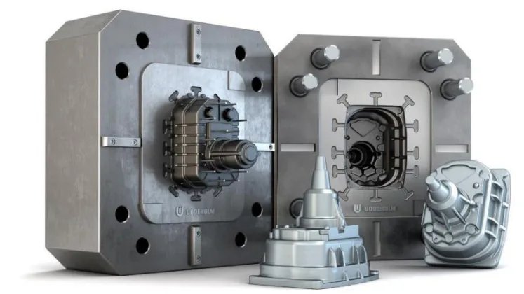
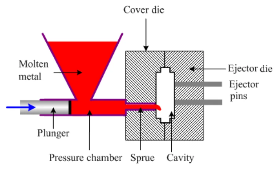
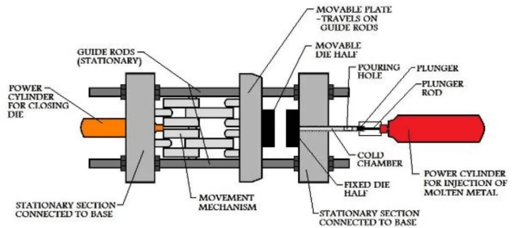
キーワード
- 主要キーワード: アディティブマニュファクチャリングHPDC金型
- 副次キーワード: 高圧ダイカスト, 熱応力, シミュレーション, 軽量金型, MAGMA, ABAQUS, コンフォーマル冷却
エグゼクティブサマリー
- 課題: アディティブマニュファクチャリング(AM)向けに設計された、薄肉形状を持つ軽量の高圧ダイカスト(HPDC)金型は、鋳造サイクルの過酷な熱的・機械的負荷に耐えることができるか?
- 手法: 従来のソリッドな金型設計と、ハニカム構造を組み込んで軽量化した設計を、鋳造シミュレーション(MAGMASoft)と熱応力解析(ABAQUS)を用いて比較しました。
- 重要なブレークスルー: 軽量化された薄肉の金型設計は、シミュレーション上の鋳造サイクルで材料の降伏強度を超える応力が発生し、破損しました。しかし、冷却性能の向上とサイクルタイムの短縮が確認されました。
- 結論: 薄肉構造への単純な置き換えはさらなる最適化なしには実現不可能ですが、アディティブマニュファクチャリングは、機械的強度を繰り返し設計で確保すれば、冷却性能の向上とサイクルタイム短縮に大きな可能性を秘めています。
課題:なぜこの研究がHPDC専門家にとって重要なのか
従来のHPDC金型製造は、長いリードタイム、機械加工による設計上の制約、そして冷却効率の限界といった課題を抱えています。特に、製品形状に沿った効率的な冷却経路(コンフォーマル冷却チャネル)の実現は困難でした。
アディティブマニュファクチャリング(AM)は、3Dプリンティング技術により、こうした制約から設計を解放し、最適な冷却性能を持つ複雑な内部構造の金型を製造する可能性を秘めています。しかし、AMを経済的に成り立たせるためには、材料使用量と造形時間を削減するための「軽量化」が不可欠です。
本研究の核心的な問いは、この軽量化された金型が、溶融金属の高温・高圧にさらされるHPDCの過酷な環境下で、構造的完全性を維持できるかという点にあります。この問いに答えることは、AMをHPDC金型製造の主流技術へと押し上げるための重要なステップとなります。
アプローチ:研究手法の解明
本研究では、従来の製造法を模した「初期設計」と、AMによる軽量化を想定した「最終設計」の2つの金型インサートモデルを比較分析しました。
手法1:初期設計(従来型モデル) 従来の機械加工による製造を想定した、完全なソリッドブロックの金型インサートです。寸法は230mm×200mm×70mmで、内部には3本の直線的な冷却チャネルが設けられています。
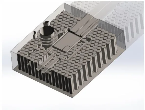
手法2:最終設計(AM向け軽量モデル) 外形寸法は初期設計と同じですが、内部の質量をハニカム構造によって大幅に削減しています。さらに、直線的な冷却チャネルに代わり、より効率的な熱除去を可能にするコンフォーマル冷却チャネルが組み込まれています。
解析ワークフロー: 1. CADモデリング(SolidWorks): 2つの金型設計を3Dモデルとして作成。 2. HPDCプロセスシミュレーション(MAGMASoft): 鋳造サイクル中の金型内の温度履歴データを取得。 3. 熱応力解析(ABAQUS): MAGMASoftから得られた温度データを入力値として、金型に発生する熱応力と変位を計算。
ブレークスルー:主要な研究結果とデータ
シミュレーションの結果、軽量設計の冷却性能における利点と、構造強度における重大な課題が明らかになりました。
結果1:冷却性能の向上とサイクルタイムの短縮
最終設計(軽量モデル)は、初期設計(ソリッドモデル)と比較して、鋳造品と金型双方の冷却速度を向上させました。グラフ(Figure 4.25、4.28)が示すように、最終設計ではサイクルタイムが約2秒短縮されました。これは、コンフォーマル冷却と、質量の減少による熱放散の効率化が寄与していると考えられ、HPDCにおける生産性向上に直結する重要な利点です。
結果2:軽量設計の構造的破損
応力解析の結果は対照的でした。初期設計では、最大フォン・ミーゼス応力はコア部で約1125 MPaとなり、使用材料の降伏強度1480 MPaを十分に下回っていました(Figure 4.31)。これは、設計が負荷に耐えうることを示しています。
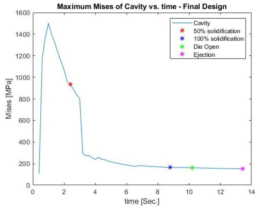
一方、最終設計では、キャビティ部で2745 MPa、コア部で1501 MPaという、降伏強度を大幅に超えるピーク応力が確認されました(Figure 4.34)。これは、ハニカム構造の薄肉部分が鋳造時の熱的・機械的負荷に耐えきれず、構造的に破損することを示唆しています。
研究開発および運用への実践的示唆
- プロセスエンジニア向け: この研究は、AMによるコンフォーマル冷却がサイクルタイムを大幅に短縮(本研究では約2秒)し、生産スループットを向上させる可能性があることを示唆しています。
- 品質管理チーム向け: 論文のFigure 4.33および4.34のデータは、薄肉部に極端な応力集中が発生することを示しており、軽量金型設計における重大な破損箇所を特定する上で重要な知見となります。
- 設計エンジニア向け: この結果は、金型を単純にハニカム構造で肉抜きするだけでは不十分であることを示しています。軽量化と、HPDCの力に耐える機械的強度を両立させるためには、トポロジー最適化や繰り返し解析が不可欠です。
論文詳細
HPDC Die design for Additive Manufacturing
1. 概要:
- 論文名: HPDC Die design for Additive Manufacturing: Simulation and Comparison of Thermal Stresses in HPDC die designed for Additive Manufacture
- 著者: Mohammadali Baradaran and Ambareeksh Tharayil Pradeep
- 出版年: 2018
- 学術誌/学会: JÖNKÖPING UNIVERSITY, School of Engineering
- キーワード: HPDC, Additive manufacturing, MAGMA simulation, Structural analysis, Casting Dies, ABAQUS simulation, Expansion, Die Life, HTC, Cooling Curves
2. 抄録:
アディティブマニュファクチャリングは、リードタイムを大幅に短縮し、従来の製造技術によって課せられる設計の複雑さの限界を取り払うことで、金型製造に利益をもたらす大きな可能性を秘めている。しかし、AMには独自の要件があり、それらはまとめて「アディティブマニュファクチャリングのための設計」として知られ、プロセスの限界を考慮に入れる。重要な要件の一つは、設計の質量効率(可能な限り軽量であるべき)である。これが満たされない場合、AMは優れた利点を持つにもかかわらず、経済的な解決策や代替手段とはなり得ない。本研究は、そのような懸念に関して構成されている。
この調査は、2つの設計バリアントの性能比較を描くことを試みる。さらに、採用された手法を研究し、アプローチの実施を文書化し、アディティブマニュファクチャリングのための設計に関連する課題を特定しようと試みた。
高圧ダイカストの1サイクル中に特定のコンポーネントの金型インサートで発生する熱応力のシミュレーションが提示される。金型インサートの初期設計は、ハニカム構造を組み込むことによる質量削減を意図して再設計される。温度変化と結果として生じる熱応力が再設計について分析され、元の設計のものと比較される。
高圧ダイカストのシミュレーションは、金型インサートと鋳造品の温度履歴を得るためにMagmaSoftで実施された。Magmaの結果が応力計算の入力として使用される、陰的非線形弾性完全連成熱変位モデルがAbaqusで設定された。
結果は、我々の特定の設計によれば、薄肉形状を持つHPDC金型は熱的および機械的負荷に耐えられないことを示している。しかし、反復的な解析と適切なトポロジー最適化により、軽量で複雑な形状の金型を成功裏に作製することができる。
3. 序論:
アディティブマニュファクチャリング(AM)は、材料を一層ずつ積層して部品を作成する技術であり、主にラピッドプロトタイピングに用いられてきた。しかし、その設計自由度の高さから、近年では最終製品の製造、特に金型製造への応用が注目されている。AMは、コンフォーマル冷却チャネルのような、従来のCNC加工では実現不可能な複雑な内部構造を可能にし、部品品質の向上とサイクルタイムの大幅な短縮(最大50%)に貢献する。
ただし、AMを金型製造に適用する上での大きな課題はコストである。材料費と加工時間がかかるため、経済的に成立させるには、設計段階で質量を最適化(軽量化)することが不可欠となる。しかし、軽量化された金型、特に薄肉の格子構造を持つ金型が、高圧ダイカスト(HPDC)プロセスの過酷な熱的・機械的負荷に耐えられるかについては、十分な知見が不足している。本研究は、この課題に取り組むことを目的とする。
4. 研究の概要:
研究トピックの背景:
本研究は、HPDC用金型インサートのアディティブマニュファクチャリング(AM)向け設計に焦点を当てる。AMの利点である設計の自由度を活かし、軽量化を実現することが経済的実行可能性の鍵となる。この研究では、ハニカム構造を導入して軽量化した金型が、鋳造サイクル中に発生する熱応力に耐えうるかをシミュレーションによって検証する。
従来の研究状況:
従来、AMはラピッドプロトタイピングや、射出成形金型へのコンフォーマル冷却チャネルの組み込みで成功を収めてきた。これによりサイクルタイムの短縮と品質向上が達成されている。しかし、射出成形よりもはるかに高温・高圧となるHPDC金型へのAMの適用、特に軽量構造の機械的信頼性に関する研究はまだ発展途上である。
研究の目的:
本研究の目的は、以下のリサーチクエスチョンに答えることである:「薄肉/壁形状を持つ軽量のHPDC金型は、鋳造サイクル中に作用する熱的および機械的負荷に耐えられるか?」この目的を達成するため、従来のソリッドな金型設計と、AMを想定した軽量なハニカム構造の金型設計の性能を比較する。
核心的な研究:
研究の核心は、2つの異なる金型設計(従来型と軽量型)の熱機械的挙動を比較することにある。まず、鋳造シミュレーションソフトウェアMAGMASoftを用いて、HPDCプロセスにおける金型と鋳造品の温度履歴を解析する。次に、その温度データを有限要素解析ソフトウェアABAQUSにインポートし、金型インサートに発生する熱応力を計算する。これにより、軽量設計が構造的に成立するかどうかを評価し、AM向け金型設計の課題を特定する。
5. 研究方法論
研究デザイン:
本研究は、比較シミュレーション研究として設計された。2つのHPDC金型インサート設計が比較対象とされた。 1. 初期設計(Initial Design): 従来の製造方法を代表する、ソリッドなブロック形状の金型。 2. 最終設計(Final Design): アディティブマニュファクチャリングを想定し、内部にハニカム構造を導入して軽量化した金型。コンフォーマル冷却チャネルも含む。
データ収集・分析方法:
解析は、複数のソフトウェアを連携させたワークフローによって実施された。 - CADモデリング: SolidWorksを使用して、2つの金型インサートと鋳造システムの3Dモデルを作成。 - 鋳造プロセスシミュレーション: MAGMASoftを使用してHPDCプロセスをシミュレーション。これにより、鋳造サイクル中の金型各部の経時的な温度分布データを取得。 - メッシュ生成: HyperMeshを使用して、応力解析用の高品質な有限要素(FE)メッシュを生成。 - 熱応力解析: ABAQUSを使用して、静的非線形陰解法による完全連成熱変位解析を実施。MAGMASoftから得られた温度データを各時間ステップの熱負荷として適用し、金型に生じるフォン・ミーゼス応力を算出した。
研究対象と範囲:
本研究の対象は、特定の部品を製造するためのHPDC金型インサートである。解析は、充填から突き出しまでの一回の鋳造サイクルに限定される。数万サイクルに及ぶ繰り返し熱負荷による疲労効果や、軽量化に伴う湯流れの変化を制御するためのゲートやランナーの再設計は、本研究の範囲外(Delimitations)とされている。
6. 主要な結果:
主要な結果:
- 冷却性能の比較: 最終設計(軽量モデル)は、初期設計(ソリッドモデル)と比較して、鋳造品と金型双方の冷却効率が向上し、サイクルタイムが約2秒短縮された(Figure 4.25、4.28)。
- 初期設計の応力解析: 初期設計の最大フォン・ミーゼス応力は、コア部で約1125 MPaに達したが、これは材料の降伏強度(1480 MPa)を下回っており、設計が鋳造サイクルに耐えることを示している(Figure 4.31)。
- 最終設計の応力解析: 最終設計では、最大フォン・ミーゼス応力がキャビティ部で2745 MPa、コア部で1501 MPaに達し、いずれも材料の降伏強度を大幅に上回った。これは、ハニカム構造の薄肉部が負荷に耐えきれず、構造的に破損することを示唆している(Figure 4.34)。
Figure Name List:
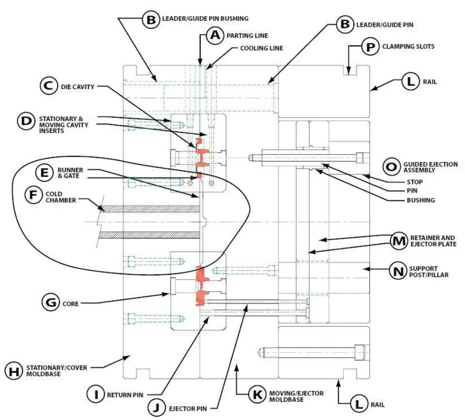
- Figure 1.1: Layout of Steps
- Figure 2.1: Die Slabs containing Die insert
- Figure 2.2 Hot Chamber HPDC setup
- Figure 2.3 Cold Chamber HPDC Setup
- Figure 2.4: Variation of IHTC value with time and temperature
- Figure 2.5: HPDC die components
- Figure 2.6- Procedure of Die design
- Figure 2.7: Selective laser Melting
- Figure 2.8: Build orientation in 3Dprinting
- Figure 3.1 : Flow of the work
- Figure 3.2 : Component - Top view.
- Figure 3.3 : Component - Bottom view.
- Figure 3.4 : Component - Isometric view, left angle.
- Figure 3.5 : Component - Isometric view, right angle.
- Figure 3.6 : Component - Sectioned view, right angle.
- Figure 3.7 : Component - Sectioned view - left angle.
- Figure 3.8 : Core (Ejector die) – Top view.
- Figure 3.9 : Core (Ejector die) – Isometric view.
- Figure 3.10 : Cavity (Cover die) – Top view.
- Figure 3.11 : Cavity (Cover die) – Isometric view.
- Figure 3.12 : Bottom view of new core with honecomb structure.
- Figure 3.13 : Transparent top view of core with honeycomb structure showing the relative position of cooling channels.
- Figure 3.14 : Left view of core with honeycomb structure showing depth of the honeycom cells.
- Figure 3.15 : Isometric view of core with honeycomb structure showing depth of the cells around coolling channles. Transparent regions are solid structure.
- Figure 3.16 : Top isometric view of cavity with honeycomb structure.
- Figure 3.17 : Bottom view of cavity with honeycomb structure.
- Figure 3.18 : Transparent top view of cavity with honeycomb structure showing the position of cooling channels around the cavity and around the inlet.
- Figure 3.19 : Transparent top isometric view of cavity with honeycomb structure showing depth of the honeycomb cells around cooling channels. Transparent regions are solid structure.
- Figure 3.20 : Transparent left view of cavity with honeycomb structure showing depth of the honeycomb cells. Transparent regins are solid structure.
- Figure 3.21 : Closer transparent view of cavity with honeycomb structure.
- Figure 3.22 : Assembly of cating materials inside Magma geometry panel. From left to right: biscuite and inlet, runner, cast (component), overflow channel.
- Figure 3.23 : Side view of casting materials assembly in Magma and their relative positions.
- Figure 3.24 : Final Assembly in Magam. Top half represents cavity (cover die) containing inlet, biscuite, cast and one set of cooling channels. Bottom half represents core (ejector die) containing runner, overflow channel, ejector pins and one set of cooling channel.
- Figure 3.25 : Geometry tree.
- Figure 3.26 : Mesh of the ejector die.
- Figure 3.27 : Mesh of casting materials and ejector die.
- Figure 3.28 : Mesh of the casting materials.
- Figure 3.29 : Material definition window and defined settings.
- Figure 3.30 : Heat transfer definition window.
- Figure 3.31 : Process timeline for a HPDC cycle.
- Figure 3.32 : Events and sub-events of a casting cycle.
- Figure 3.33 : Active shot chamber length.
- Figure 3.34 : positio of plunger in shot sleeve when port is covered.
- Figure 3.35 : Shot curve definition panel.
- Figure 3.36 : Filling shot curve.
- Figure 3.37 : Intensification difinition window.
- Figure 3.38 : Die open definition window.
- Figure 3.39 : Dir tempering control window.
- Figure 3.40 : Results order condistion window.
- Figure 3.41: Top view from assembly of component, air pockets, and cooling channels in core.
- Figure 3.42 : Isometric view from assembly of component, air pockets, and cooling channels in core.
- Figure 3.43 : Assembly of air pockets and cooling channels in cavity.
- Figure 3.44 : Position of inserts in surrounding walls – Final design.
- Figure 3.45 : Mesh for the new cavity - Top.
- Figure 3.46 : Mesh for the new cavity – Bottom.
- Figure 3.47 : Mesh for the new core – Bottom.
- Figure 3.48 : Material definition window – Final design.
- Figure 3.49 : Heat transfer definition window for final design.
- Figure 3.50 : Size and bias panel of 2D auto meshing.
- Figure 3.51: Small features on core that need finer mesh than sorrounding areas.
- Figure 3.52 : Small feature shown in Figure 3.51 from different angle.
- Figure 3.53 : Surface deviation panle of 2D automeshing.
- Figure 3.54 : Mesh transition on core.
- Figure 3.55 : Check element tab where element quality check can be carried out for 2D and 3D mesh.
- Figure 3.56 : Edge panel where operation for finding free edges and T-connections is carried out.
- Figure 3.57 : Tetramesh control panel of tetramesh in 3D meshing.
- Figure 3.58 : tetramesh control panel for executing 3D mesh creation. 2D mesh is selected as input for Fixedtrias/quads to tetramesh.
- Figure 3.59 : Meshed cavity, final design, top view.
- Figure 3.60 : Meshed cavity, final design, side view.
- Figure 3.61 : Meshed cavity, final design, bottom view.
- Figure 3.62 : a sectioned view showing the solid elements, cavity, final design.
- Figure 3.63 : Side sectioned view showing solid elements, cavity, final design.
- Figure 3.64 : Meshed core, top view, final design.
- Figure 3.65 : Meshed core, showing mesh transition, final design.
- Figure 3.66 : Meshed core, bottom view, new design.
- Figure 3.67 : Meshe core, bottom view, closer look, final design.
- Figure 3.68 : Sectined view of core showing solid element, final deesign.
- Figure 3.69 : Sectined view of core showing solid element, final deesign.
- Figure 3.70 : Meshed cavity, top view, initial design.
- Figure 3.71 : Meshed cavity, isometric top view, initial design.
- Figure 3.72 : Meshed cavity, bottom view, initial design.
- Figure 3.73 : Sectioned view of cavity shoeing solid elements, initial design.
- Figure 3.74 : Meshed core, top view initial design.
- Figure 3.75 : Meshed core, isometri top view, initial design.
- Figure 3.76 Sectined view of core showing solid elements, initrial design.
- Figure 3.77 : Solver deck export panel for mesh export in HyperMesh.
- Figure 3.78 : Entity State panel where components of interest can be selected for mesh export.
- Figure 3.79 : Model tree view in Abaqus.
- Figure 3.80 : Part copy window where joint parts in assembly can be detached.
- Figure 3.81 : Assembly in Abaqus.
- Figure 3.82 : Basic tab of step definition window in Abaqus.
- Figure 3.83 : Increment tab of step definition in Abaqus.
- Figure 3.84 : Die movment constrained along X axis.
- Figure 3.85 : Die Movement constrained alonf Y axix.
- Figure 3.86 : Bottom surface of the cavity is pinned. Movement of die inserts along Z axis is restricted.
- Figure 3.87 : Defining a uniform load applied on the top of the core.
- Figure 3.88 : Defining the contact surface in interaction module.
- Figure 3.89 : Definition of tangential behaviour in interaction properties.
- Figure 3.90 : Definition of normal behaviour in interaction properties.
- Figure 3.91: Assigning initial temperature of the inserts in predefined field.
- Figure 3.92 : Export file window in Magma.
- Figure 3.93 : Material selection window in Magma.
- Figure 3.94 : Results category selection for export in Magma.
- Figure 3.95 : An example of temperature file generated by result export in Magma (Left). Same temperature file after being modified by MATLAB.
- Figure 4.1 : Temperature profile of core at the end of filling (0.38 s, Max Temp = 178 ºC).
- Figure 4.2 : Temperature profile of core at 50% solidification (t = 2.2 s, Max T= 359 ºC).
- Figure 4.3 : Temperature profile of core at 100% solidification (t = 8.91 s, Max T= 348 ºC).
- Figure 4.4 : Temperature profile of core at die open (t = 10.12 s, Max T= 327 ºC).
- Figure 4.5 : Temperature profile of core at ejection (t = 15.14 s, Max T= 223 ºC).
- Figure 4.6 Temperature profile of cavity at the end of filling (t = 0.38 s, Max T= 170 ºC).
- Figure 4.7 Temperature profile of cavity at 50% solidification (t = 2.2 s, Max T= 367 ºC).
- Figure 4.8 Temperature profile of cavity at 100% solidification (t = 8.91 s, Max T= 310 ºC).
- Figure 4.9 Temperature profile of cavity at die open (t = 10.12 s, Max T= 298 ºC).
- Figure 4.10 Temperature profile of cavity at ejection (t = 15.14 s, Max T= 215 ºC).
- Figure 4.11 Temperature profile of core at 50% solidification (t = 1.80 s, Max T= 361 ºC).
- Figure 4.12 Temperature profile of core at 100% solidification (t = 7.35 s, Max T= 367 ºC).
- Figure 4.13 Temperature profile of core at die open (t = 8.44 s, Max T= 348 ºC).
- Figure 4.14 Temperature profile of core at ejection (t = 13.45 s, Max T= 251 ºC).
- Figure 4.15 Temperature profile of core at 50% solidification (t = 1.80 s, Max T= 385 ºC).
- Figure 4.16 Temperature profile of core at 100% solidification (t = 7.35 s, Max T= 322 ºC).
- Figure 4.17 Temperature profile of core at die open (t = 8.44 s, Max T= 306 ºC).
- Figure 4.18 Temperature profile of cavity at ejection (t = 13.45 s, Max T= 194 ºC).
- Figure 4.19 : Cooling behavior of cavity- initial design.
- Figure 4.20 : Cooling behavior of core- initial design.
- Figure 4.21 : Superimposed cooling behaviors of cavity and core - initial design.
- Figure 4.22 : Cooling behavior of cavity- final design.
- Figure 4.23 : Cooling behavior of core- final design.
- Figure 4.24 : Superimposed cooling behaviors of cavity and core – final design.
- Figure 4.25 : Superimposed cooling behaviors of cavity and core – initial and final design (new design).
- Figure 4.26 : Cooling behavior of cast in initial design.
- Figure 4.27 : Cooling behaviour of cast in final design (new design).
- Figure 4.28 : Superimposed cooling behaviors of cast in initial and final design (new design).
- Figure 4.29 : Unaveraged maximum mises stress Vs. time for cavity initial design.
- Figure 4.30 : Unaveraged maximum mises stress Vs. time for core initial design.
- Figure 4.31 : Superimposed unaveraged maximum mises stresses of core and cavity – Initial design.
7. 結論:
本研究で分析された最終設計(軽量モデル)は、鋳造サイクル中に破損する。サイクル中に誘発される高い応力値は、本研究で使用された材料の降伏強度よりも高い。
最終設計では、鋳造品と金型の両方の冷却挙動に改善が見られる。最終設計で生じる高い応力は、より効果的な冷却のために速やかに消散する。
最終設計では、キャビティと比較してコアでの応力発生がはるかに大きい。
薄肉部の壁厚を増すことで、最終設計の金型は高い応力に耐えられるように作ることができる。新しい設計による質量の削減が、加熱サイクルによって生じる応力に対応できることを確認する必要がある。
8. 参考文献:
- [1] M. Attaran, ”The rise of 3-D printing: The advantages of additive anufacturing over traditional manufacturing,” Elsevier, p. 12, 2017.
- [2] Charisios Achillas, Dimitrios Tzetzis & Maria Olga Raimondo, ”Alternative production strategies based on the compaison of additive and traditional manufacturing technologies,” International Journal of Production Research, vol. 55, pp. 3497-3509, 2017.
- [3] Christoph Klahn, Bastian Leutenecker, Mirko Meboldt, ”Design Strategies for the process of additive manufacturing,” Elsevier , pp. 230-235, 2015.
- [4] T. Vaneker, ”The role of design for additive manufacturing in the successful economical introduction of AM,” Elsevier, pp. 181-186, 2017.
- [5] Mahmoud Dinar, David W. Rosen, ”A design for additive manufacturing ontology,” Journal of compting and information sience in engineering , vol. 17, p. 9, 2017.
- [6] Sebastian Hällgren, Lars Pejryd, Jens Ekengren, ”(Re)Design for additive manufacturing,” Elsevier , pp. 246-251, 2016.
- [7] Kranz, H. D och E. C, ”Design guidelines for laser additive manufacturing of light weight structures in TiAl6V4,” Journal of Laser applications, 2016.
- [8] R. Leal, F.M. Barreiros, L. Alves, F. Romeiro, J. C. Vasco, M. Santos, ”Additive manufacturing tooling for automotive industry,” Journal of advanced manufacturing technology , pp. 1671-16-76, 2017.
- [9] Konstantinos Salonitis, Saeed Al Zarban, ”Redesign optimization for manufaturing using additive layer techniques,” Elsevier, pp. 193-198, 2015.
- [10] B. Andresen, Die Casting Engineering- A hydraulic, thermal and mchanical process, New York: Marcel Dekker, 2005.
- [11] M.Winkler, L. Kallien och T. Feyertag, ”Correlation between process parameters and quality charecterestics in aluminum high pressure die casting,” North American Die Casting Association, 2015.
- [12] P. Senthiil, M. Chinnapandian och A. Sirrussshti, ”Optimization of process parameters in cold chamber die casting process using Taguchi Method,” International Journal of innovative science, vol. 1, nr 6, 2014.
- [13] M. S. Dargusch, A. Hamasaiid, G. Dour, T. Loulou, C. J. Davidson och D. H.StJohn, ”The Accurate Determination of Heat Transfer Coefficient and its Evolution with Time During High Pressure Die Casting of Al‐9 %Si‐3 %Cu and Mg‐9 %Al‐1 %Zn Alloys,” Advanced Engineering Materials, p. 997, 2007.
- [14] R. Ranjan, R. Samant och S. Anand, ”Integration of Design for Manufacturing Methods with Topology Optimisation in Additive Manufacturing,” Journal of Manufacturing Science and Engineering, vol. 139, nr 6, 2016.
- [15] A. Rosochowski A., ”Rapid Tooling: The State of the Art,” Journal of Material Processing technology, vol. 106, pp. 191-198, 2000.
- [16] D. T, J. Zuback, H. Wei, T. Mukerjee, E. J.W., M. J.O., B. A.M., A. Wilson-Heid, A. De och W. Zhang, ”Additive manufacture of metallic components,” Progress in Materials Science, vol. 92, pp. 112-224, 2018.
- [17] R. Stolt, S. Andre och F. Elgh, ”Introducing Inserts for Die casting manufactured by Selective Laser Sintering,” Procedia Manufacturing, 2018.
- [18] C. K. Mario Valdez, E. J. Faierson och . I. Jasiuk, ”Induced porosity in Super alloy718 through the laser additive manufacturing process: Microstructure and Mechanical Properties,” Journal of Alloys and Compounds, pp. 757-764, 2017.
- [19] M. JO, ”Additive Manufacture of metals,” Springer series in Material science, vol. 258, 2017.
- [20] A. KN, G. SM, M. LE, M. E, S. PW och H. J, ”Microstructures and mechanical properties of Inconel 718 fabricated by selective laser melting,” Acta Mater , pp. 2229-2239, 2012.
- [21] C.-C. Kuo och M.-R. Li, ”Development of sheet metal forming dies with excellent mechanical properties using additive manufacturing and rapid tooling technologies,” Journal of Advanced Engineering Materials, vol. 90, pp. 21-25, 2017.
- [22] P. HS och P. NH, ”Design of conformal cooling channels for an automotive part,” International Journal of automotive technology, vol. 10, nr 1, pp. 87-93, 2009.
- [23] A. Armillotta, R. Baraggi och S. Fasoli, ”SLM tooling for die casting with conformal cooling channels,” International Journal of Advanced Manufacturing Technology, vol. 71, pp. 573-583, 2014.
専門家Q&A:あなたの疑問に答えます
Q1: なぜ軽量化の手法としてハニカム構造が選ばれたのですか?
A1: 論文では明確な選定理由は述べられていませんが、一般的にハニカム構造は、その高い強度対重量比と、面外方向の優れた圧縮特性から、軽量化コア材として広く利用されています。この研究では、AMの経済性を高めるための質量削減という目的に対し、構造的利点を持つハニカム構造を適用したと考えられます。
Q2: 軽量設計における破損の主な原因は何でしたか?
A2: 主な原因は、ハニカム構造を構成する薄い壁(リブ)における極端な応力集中です。シミュレーション結果(Figure 4.34)が示すように、鋳造時の急激な温度変化による熱膨張と、機械的な型締め力が組み合わさり、薄肉部がその負荷に耐えきれず、材料の降伏強度を大幅に超える応力が発生しました。
Q3: このシミュレーションは1サイクルのみですが、数千サイクルに及ぶ実際の生産現場では結果はどのように異なると考えられますか?
A3: 論文でもこの点は限界として認識されています。実際の生産では、繰り返し熱負荷による「熱疲労」が金型寿命を決定する主要因となります。本研究では解析されていませんが、軽量設計の薄肉部では応力集中が激しいため、熱疲労による亀裂がソリッドな金型よりも早期に発生・進展する可能性が非常に高いと予測されます。
Q4: 使用されたソフトウェアのワークフローと、その中での課題は何でしたか?
A4: ワークフローは、SolidWorks(CAD)→ MAGMASoft(鋳造解析)→ HyperMesh(メッシュ生成)→ ABAQUS(応力解析)という流れでした。最大の課題は、異なるソフトウェア間でデータを連携させること、特にMAGMASoftの差分法(FDM)メッシュから得られた温度データを、ABAQUSの有限要素法(FEM)メッシュに正確にマッピングすることでした。これにはカスタムのMATLABスクリプトが必要で、両メッシュの精密な位置合わせが結果の精度を左右しました。
Q5: 軽量金型は破損したとのことですが、このアプローチはHPDCには不向きなのでしょうか?
A5: この特定の設計は失敗しましたが、アプローチ自体が否定されたわけではありません。論文の結論部では、今回の結果を踏まえ、反復的な解析と適切なトポロジー最適化によって、負荷のかかる部分の壁厚を増すなど、強度と軽量化のバランスを取ることで、成功する軽量金型を製造することは可能であると示唆しています。単純な肉抜きではなく、より高度な設計手法が求められます。
結論:より高い品質と生産性への道を開く
本研究は、アディティブマニュファクチャリングHPDC金型が、サイクルタイム短縮という大きな可能性を秘めている一方で、安易な軽量化設計には構造的破損という重大なリスクが伴うことを明確に示しました。成功の鍵は、シミュレーションを駆使した高度な設計アプローチにあります。熱応力が集中する箇所を正確に予測し、必要な強度を確保しながら質量を最適化する、反復的な設計プロセスが不可欠です。
CASTMANでは、最新の業界研究を応用し、お客様がより高い生産性と品質を達成するためのお手伝いをすることをお約束します。この論文で議論された課題がお客様の事業目標と一致する場合、これらの原則をお客様のコンポーネントにどのように実装できるか、ぜひ当社のエンジニアリングチームにご相談ください。
著作権情報
このコンテンツは、Mohammadali Baradaran氏およびAmbareeksh Tharayil Pradeep氏による論文「HPDC Die design for Additive Manufacturing」に基づく要約および分析です。
出典: Jönköping University, School of Engineering, December 2018
この資料は情報提供のみを目的としています。無断での商業利用は禁じられています。 Copyright © 2025 CASTMAN. All rights reserved.