1. 概要:
- 論文タイトル: A study of an industrial counter pressure casting process for automotive parts
- 著者: Jun Ou, Chunying Wei, Savanna Logue, Steve Cockcroft, Daan Maijer, Yacong Zhang, Zhi Chen, Lateng A
- 発行年: 2021
- 発行学術誌/学会: Journal of Materials Research and Technology
- キーワード: CPC process, Plant trial, Data acquisition, Model development, ProCAST
2. 抄録:
カウンタープレッシャー鋳造(Counter pressure casting, CPC)は、アルミニウム部品生産における優れた能力が報告されていることから、低圧ダイカスト(LPDC)の代替として自動車製造業界で注目されています。本研究は、CPCの特徴的な要素(適用されるチャンバー圧力)が、プロセス中に生じる流体の流れや熱輸送、そして鋳造品質にどのように影響するかを初めて包括的に調査したものです。自動車用サスペンションコントロールアームを製造する商用CPCプロセスから、2つのプロセス条件(標準生産条件と低背圧条件)で大量の高品質データを取得しました。データ分析の結果、凝固中の熱伝達、鋳放し状態の微細組織、機械的特性に関して、2つのプロセス圧力条件間に有意な差はないことが示されました。一般的に、金型内で測定された温度は2つのプロセス条件で10℃以内の差であり、鋳物から得られたサンプルの最大引張強さ(UTS)も2つの条件間で7%以内の差でした。さらに、2つのプロセス条件で得られた二次デンドライトアーム間隔(SDAS)にも測定可能な差は観察されませんでした。しかし、チャンバー背圧を適用すると、充填段階でのベント(ガス抜き)速度が著しく低下し、低背圧条件と比較して充填時間が12秒遅延しました。元々LPDC用に開発された計算モデリング手法をCPCプロセスのシミュレーションに適用しました。このモデルは、高背圧条件で観察されたベント速度の低下による充填遅延を考慮するために、圧力曲線を調整するだけで済みました。予測結果は測定データとよく相関しており、このモデリング手法が永久鋳型ダイカストプロセスに広く適用可能であることを示しています。
3. 序論:
エネルギーおよび排出ガスに関する厳しい規制と社会的圧力により、自動車業界では鉄系鋳物の代替として軽量アルミニウム部品の使用が増加しています。これらの部品の生産には、低圧ダイカスト(LPDC)と高圧ダイカスト(HPDC)が最も広く用いられています。カウンタープレッシャー鋳造(CPC)は比較的新しい技術であり、背圧をかけながら金型を充填することでLPDCよりも高品質な部品を生産すると主張されています。コンピュータベースのシミュレーションは鋳造プロセスの最適化における重要なツールとなっていますが、CPCへの適用は限定的であり、プロセスの利点とシミュレーションモデルの両方を検証するための高品質な産業データが不足しています。本研究は、商用CPCプロセスを広範囲にわたって特性評価し、背圧が充填および凝固挙動に与える影響を定量的かつ包括的に評価し、計算モデリング手法を検証することを目的としています。
4. 研究の要約:
研究テーマの背景:
CPCプロセスは、金型システムが圧力チャンバー内に配置されるという点でLPDCの一種です。このチャンバーを加圧することにより、充填と凝固の段階が従来のLPDCよりも高い絶対圧力下で行われます。この圧力上昇により、自由表面の乱流が減少し、酸化膜の巻き込みが抑制されること、熱伝達が向上し微細組織が微細化すること、そして収縮によるポロシティ(鋳巣)が減少し、鋳造品質が向上すると主張されています(Ref. [9], [18])。しかし、これらの主張を裏付ける、工業生産から得られた査読済みのエビデンスは不足しています。
先行研究の状況:
CPCプロセスに関する先行研究は限られています。いくつかの計算モデリング研究が報告されており、ポロシティ形成の予測(Ref. [10])やCPCとLPDCプロセスの比較(Ref. [19])に焦点を当てています。基本的に、両プロセスは同じモデリング原理で記述でき、主な違いは充填と凝固中の圧力レジームです。しかし、これらのモデルとCPCの利点を工業規模の設備を用いて包括的に実験的に検証した研究は、これまで文献にありませんでした。
研究の目的:
本研究の第一の目的は、CPCプロセスで適用されるチャンバー圧力(背圧)が、流体の流れ、熱輸送、および最終的な鋳造品質に与える影響を包括的かつ定量的に調査することです。第二の目的は、元々LPDC用に開発された計算モデリング手法をCPCプロセスに適用し、その精度と堅牢性を評価して、永久鋳型ダイカストプロセスへのより広範な適用可能性を評価することです。
研究の核心:
本研究の核心は、A356アルミニウム合金製の自動車用コントロールアームを生産する商用CPC機で実施された広範なプラント内特性評価キャンペーンです。高い背圧を伴う標準生産条件(CPC-SP)と、大気圧のチャンバー圧力でLPDCプロセスを模倣した条件(CPC-LP)という2つのプロセス条件を比較しました。この研究には、詳細な金型内温度測定、鋳造後の微細組織(SDAS)および機械的特性(UTS)の分析、CTスキャンによるポロシティ評価が含まれます。これらの実験結果は、ProCASTで開発されたCPCプロセスの計算モデルを検証するために使用されました。
5. 研究方法論
研究設計:
本研究は比較実験研究として設計されました。工業用CPCプロセスを用いて、以下の2つの異なる条件下で自動車用コントロールアームを製造しました。
- CPC-SP(標準生産): 炉内およびチャンバー圧力を高めた標準プロセス。
- CPC-LP(低背圧): チャンバー圧力を大気圧(0 mbar-gauge)に設定し、従来のLPDCプロセスを模倣。
チャンバー背圧の効果を分離するため、充填を駆動する圧力差や水冷スケジュールなど、他のすべてのプロセスパラメータは両条件で同一に保たれました。
データ収集・分析方法:
- プラント内データ収集: 合計65個のKタイプ熱電対を金型セクション、冷却チャネル、および周辺環境に設置しました。データ収集(DAQ)システムを用いて4Hzでデータを収集し、周期的定常状態における金型の熱的挙動を監視しました。
- 鋳造品の特性評価:
- ポロシティ: X線コンピュータ断層撮影(CT)を用いて鋳造品を検査し、収縮に起因するポロシティを特定しました。
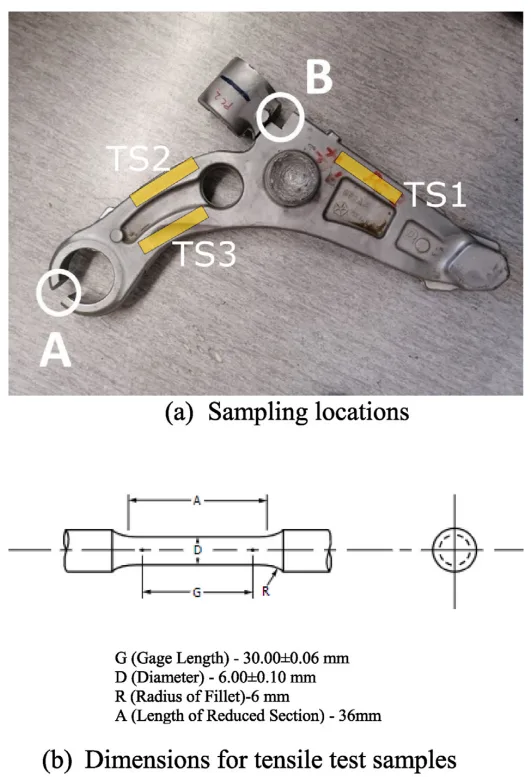
- 微細組織: 鋳造品の2つの箇所からサンプルを採取し、光学顕微鏡と線交差法を用いて二次デンドライトアーム間隔(SDAS)を評価しました。
- 機械的特性: 3つの箇所から引張試験片を機械加工し、ASTM B 557M規格に従って試験を行い、最大引張強さ(UTS)を測定しました。
- 計算モデリング: 有限要素法(FEM)ソフトウェアであるProCASTを用いてCPCプロセスをシミュレーションしました。モデルは以前に検証されたLPDCモデル(Ref. [17])を応用し、金型の温度推移と凝固順序を予測するために使用されました。
研究テーマと範囲:
本研究は、A356アルミニウム合金製自動車用コントロールアームを対象とした工業用CPCプロセスに焦点を当てています。研究範囲は、金型充填、凝固から鋳造後の分析まで、プロセス全体を網羅しています。調査された主要なテーマは、チャンバー背圧が以下の項目に与える影響です。
- 金型充填のダイナミクスと時間。
- 鋳造サイクル中の金型内の熱履歴。
- 結果として得られる鋳放し状態の微細組織(SDAS)と機械的特性(UTS)。
- 収縮に起因するポロシティの形成。
- CPCプロセスのシミュレーションに対するLPDCベースの計算モデルの適用可能性と精度。
6. 主な結果:
主な結果:
- 充填遅延: チャンバー背圧を適用した(CPC-SP条件)主な効果は、低背圧条件(CPC-LP)と比較して金型充填が約12秒大幅に遅延したことです。この遅延は、ベント効率の低下に起因すると考えられます。高圧により、金型キャビティから排出されるべき空気の粘性が増加するためです。
- 熱履歴: 充填遅延を考慮に入れると、金型内の温度推移は両プロセス条件で非常に類似していました。測定された温度差は一般的に10℃以内で、チャンバー背圧が熱履歴や金型/鋳物界面の熱伝達に大きな影響を与えないことを示しています。これは、CPCが冷却速度を向上させるという主張と矛盾します。
- 微細組織と機械的特性: 両条件間で、鋳放し状態の微細組織や機械的特性に有意な差は観察されませんでした。二次デンドライトアーム間隔(SDAS)と最大引張強さ(UTS)は統計的に同等であり、このケースでは背圧の適用によって鋳造品質が測定可能なほど向上しないことを示唆しています。
- 計算モデルの検証: 元々LPDC用に開発された計算モデルが、CPCプロセスに成功裏に適用されました。このモデルは、観察された充填遅延を考慮するために圧力曲線を単純に調整するだけで、実験的な温度データを正確に予測しました。これは、このモデリング手法が堅牢であり、永久鋳型鋳造プロセスに広く適用可能であることを示しています。
- ポロシティ: CPC-SP条件に関するモデル予測とCTスキャン結果の両方で、指向性凝固がほぼ達成されており、凝固末期に特有の微細で分散したポロシティが一つの領域で観察されただけでした。
図のタイトルリスト:
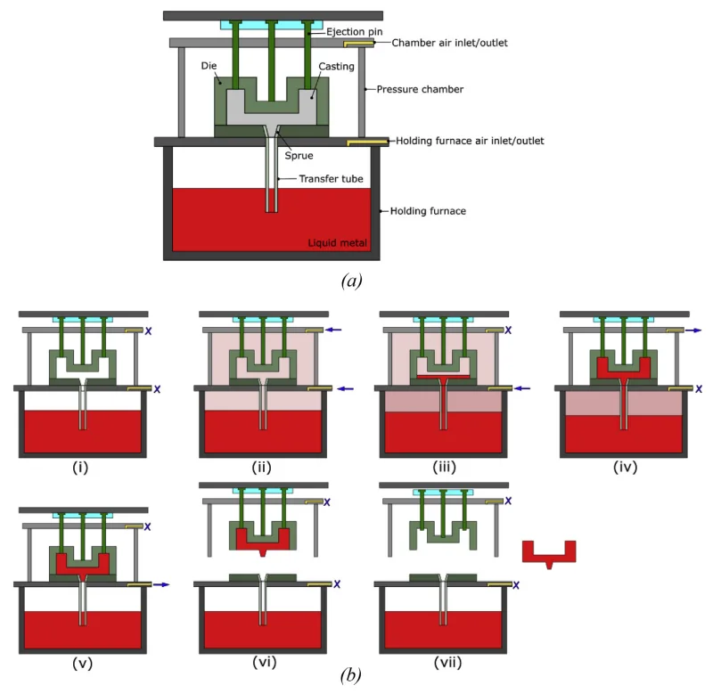
- Fig. 1 – Schematic of the CPC machine and process procedure (a) Structure of the CPC machine (b) Major steps of the CPC process: (i) pressure chamber closed; (ii) furnace and pressure chamber are pressurized; (iii) furnace pressure is further increased slowly; (iv) chamber pressure is quickly released; (v) furnace pressure is released; (vi) chamber and die are opened; and (vii) the cast part is ejected.
- Fig. 2 – Geometry of the die sections and the cast component (control arm) and the mesh used for analysis.
- Fig. 3 – Schematic showing locations of the cooling elements and TCs. Note: the distances between the TCs and die/casting interface are given in Table 2.
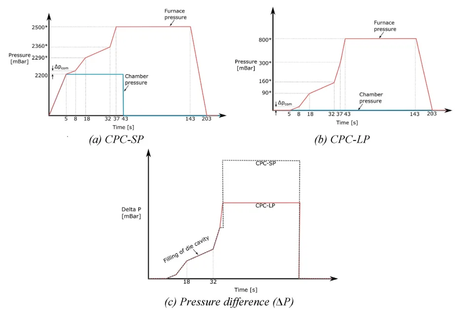
- Fig. 4 – Furnace pressure, chamber pressure and resulting pressure differential variation with time for the CPC-SP and CPC-LP process conditions.
- Fig. 5 – Cooling timings - refer to Fig. 3 (a) for the locations of cooling channels on the top die.
- Fig. 6 – Samples removed from the control arm for microstructural analysis and tensile tests.
- Fig. 7 – Schematic of spot or finger-type cooling element used in the CPC process.
- Fig. 8 – Temperatures measured from three sequential cycles.
- Fig. 9 – Temperatures measured by different TCs from a cyclic steady state cycle.
- Fig. 10 – Comparison of temperatures measured from different process conditions.
- Fig. 11 – Optical microscopy observation of the samples.
- Fig. 12 – SDAS measurements.
- Fig. 13 – Tensile test results.
- Fig. 14 – Temperature comparison between the model results and measured data.
- Fig. 15 – Solidification sequence - represented by contours of solid fraction limited to 0.7.
- Fig. 16 – Location of porosity detected by CT scanning.
7. 結論:
本研究は、工業的なCPCプロセスにおける適用チャンバー圧力の影響に関する初の包括的な調査を提供します。広範なプラント内データと鋳造後の特性評価の分析により、増加した背圧の主な効果は、ベント効率の低下に起因する大幅な充填遅延(約12秒)であることが明らかになりました。一部の業界の主張とは対照的に、本研究では、チャンバー圧力が金型内の熱履歴の推移に有意な影響を与えず、最終的な鋳物の微細組織(SDAS)や機械的特性(UTS)にも測定可能な改善をもたらさないことがわかりました。さらに、本研究は、元々LPDC用に開発された計算モデリング手法が、わずかな変更を加えるだけでCPCプロセスに広く適用可能であることを成功裏に実証し、さまざまな永久鋳型ダイカスト操作に対するその堅牢性を確認しました。
8. 参考文献:
- [1] Martin Kahl XB. Special report: vehicle lightweighting. 2016.
- [2] Isenstadt A, German J, Bubna P, Wiseman M, Venkatakrishnan U, Abbasov L, et al. Lightweighting technology development and trends in US passenger vehicles. Int. Counc. Clean Transp. Work. Pap. 2016;25.
- [3] Bonollo F, Urban J, Bonatto B, Botter M. Gravity and low pressure die casting of aluminium alloys: a technical and economical benchmark. La Metall Ital 2005:23–32.
- [4] Butler WA. High pressure die casting; encyclopedia of materials. Science and Technology; 2001.
- [5] Zhang B, Maijer DM, Cockcroft SL. Development of a 3-D thermal model of the low-pressure die-cast (LPDC) process of A356 aluminum alloy wheels. Mater Sci Eng, A 2007;464:295–305. https://doi.org/10.1016/j.msea.2007.02.018.
- [6] Collot J. Review OF new process technologies IN the aluminum die-casting industry. Mater Manuf Process 2001;16:595–617. https://doi.org/10.1081/AMP-100108624.
- [7] Hu H, Chen F, Chen X, Chu YL, Cheng P. Effect of cooling water flow rates on local temperatures and heat transfer of casting dies. J Mater Process Technol 2004;148:57–67. https://doi.org/10.1016/j.jmatprotec.2004.01.040.
- [8] Liu GW, Morsi YS, Clayton BR. Characterisation of the spray cooling heat transfer involved in a high pressure die casting process. Int J Therm Sci 2000;39:582–91. https://doi.org/10.1016/S1290-0729(00)00207-6.
- [9] Vijayaram TR. CounterPressure casting techniquefor aluminium foundries. 2012.
- [10] Katzarov IH, Arsov YB, Stoyanov P, Zeuner T, Buehrig-Polaczek A, Sahm PR. Porosity formation in axi-symmetric castings produced by counter-pressure casting method. Int J Heat Mass Tran 2001;44:111–9. https://doi.org/10.1016/S0017-9310(00)00085-5.
- [11] Ou J, Wei C, Maijer D, Cockcroft S, Zhang Y, Chen Z, et al. Modelling of an industrial die casting process for the production of aluminum automotive parts. In: Proceedings of the IOP conference series: materials science and engineering, vol. 861. Institute of Physics Publishing; 2020. p. 12030.
- [12] Zhu J, Cockcroft S, Maijer D. Modeling of microporosity formation in A356 aluminum alloy casting. Metall Mater Trans A 2006;37:1075–85. https://doi.org/10.1007/s11661-006-1027-5.
- [13] Reilly C, Duan J, Yao L, Maijer DM, Cockcroft SL. Process modeling of low-pressure die casting of aluminum alloy automotive wheels. JOM 2013;65:1111–21. https://doi.org/10.1007/s11837-013-0677-1.
- [14] Duan J, Maijer D, Cockcroft S, Reilly C. Development of a 3D filling model of low-pressure die-cast aluminum alloy wheels. Metall Mater Trans A 2013;44:5304–15. https://doi.org/10.1007/s11661-013-1654-6.
- [15] Yao L, Cockcroft S, Zhu J, Reilly C. Modeling of microporosity size distribution in aluminum alloy A356. Metall Mater Trans A 2011;42:4137–48. https://doi.org/10.1007/s11661-011-0811-z.
- [16] Ou J, Wei C, Cockcroft S, Maijer D, Zhu L, A L, et al. Advanced process simulation of low pressure die cast A356 aluminum automotive wheels — Part I, process characterization. Metals (Basel). 2020;10:563. https://doi.org/10.3390/met10050563.
- [17] Ou J, Wei C, Cockcroft S, Maijer D, Zhu L, A L, et al. Advanced process simulation of low pressure die cast A356 aluminum automotive wheels—Part II modeling methodology and validation. Metals (Basel). 2020;10:1418. https://doi.org/10.3390/met10111418.
- [18] Jahangiri A, Marashi SPH, Mohammadaliha M, Ashofte V. The effect of pressure and pouring temperature on the porosity, microstructure, hardness and yield stress of AA2024 aluminum alloy during the squeeze casting process. J Mater Process Technol 2017;245:1–6. https://doi.org/10.1016/j.jmatprotec.2017.02.005.
- [19] Georgiev GE, Stanev L, Georgiev M, Maneva A, Stanev S. Optimization OF the process OF casting formation BY CPC method using computer simulation. 2017.
- [20] Vandersluis E, Ravindran C. Comparison of measurement methods for secondary dendrite arm spacing. Metallogr. Microstruct. Anal. 2017;6:89–94. https://doi.org/10.1007/s13632-016-0331-8.
- [21] Wei C, Ou J, Fan P, Mehr F, Maijer D, Cockcroft S, et al. Toward the development of a thermal-stress model of an industrial counter pressure casting process. In: Proceedings of the IOP conference series: materials science and engineering, vol. 861. Institute of Physics Publishing; 2020. p. 12062.
9. 著作権:
- 本資料は、「Jun Ou, et al.」による論文です。「A study of an industrial counter pressure casting process for automotive parts」に基づいています。
- 論文の出典: https://doi.org/10.1016/j.jmrt.2021.11.124
本資料は上記論文に基づいて要約したものであり、商業目的での無断利用を禁じます。
Copyright © 2025 CASTMAN. All rights reserved.
論文の要約:
本研究は、工業用自動車部品に対するカウンタープレッシャー鋳造(CPC)プロセスにおけるチャンバー背圧の影響を包括的に調査したものです。その結果、背圧は鋳型の充填を約12秒遅延させるものの、鋳物の熱履歴、微細組織、または機械的特性には測定可能な影響を与えないことが示されました。また、LPDC用の計算モデリング手法が、わずかな調整でCPCプロセスに広く適用可能であることも実証しています。
研究に関する主な質問と回答:
Q1. CPCプロセスの金型充填段階でチャンバー背圧をかけることの最も大きな影響は何ですか?
A1. チャンバー背圧を適用すると、充填中のベント(ガス抜き)速度が著しく低下し、低背圧(LPDC様)条件と比較して充填時間が約12秒大幅に遅延します。(出典:「A study of an industrial counter pressure casting process for automotive parts」、抄録およびセクション6)
Q2. CPCプロセスの圧力上昇は、低圧プロセスと比較して鋳物の機械的特性を向上させたり、微細組織を微細化させたりしますか?
A2. いいえ、本研究では機械的特性や鋳放し状態の微細組織に有意な差は認められませんでした。最大引張強さ(UTS)は両プロセス条件で7%以内の差であり、二次デンドライトアーム間隔(SDAS)にも測定可能な差はありませんでした。(出典:「A study of an industrial counter pressure casting process for automotive parts」、抄録およびセクション5.2)
Q3. CPCは金型と鋳物間の熱伝達を向上させると主張されていますが、本研究はその主張を支持しますか?
A3. いいえ、本研究はその主張を支持しません。金型内温度データの分析では、高背圧条件と低背圧条件の間に有意な差は見られず、ほとんどの温度プロファイルは10℃未満の差であったことから、チャンバー圧力が熱履歴や界面熱伝達に大きな影響を与えないことが示されました。(出典:「A study of an industrial counter pressure casting process for automotive parts」、セクション5.1.1)
Q4. 標準的なCPCプロセス(CPC-SP)と低背圧プロセス(CPC-LP)とで、金型内の熱履歴はどのように比較されますか?
A4. 12秒の充填遅延を考慮すると、金型内のさまざまな場所での温度推移は、両プロセス条件で非常に類似しています。ほとんどの場所で0~10℃の範囲の温度差しか示さず、全体的な熱履歴はチャンバー圧力によって大きな影響を受けないことがわかります。(出典:「A study of an industrial counter pressure casting process for automotive parts」、セクション5.1.1およびFigure 10)
Q5. LPDCプロセス用に開発された計算モデルを、CPCプロセスのシミュレーションに使用することはできますか?
A5. はい、本研究は、元々LPDC用に開発された計算モデリング手法が、CPCプロセスのシミュレーションに成功裏に適用できることを実証しました。モデルは、高背圧によるベント速度の低下に起因する充填遅延を考慮するために、圧力曲線を調整するだけで済みました。(出典:「A study of an industrial counter pressure casting process for automotive parts」、抄録およびセクション6)
Q6. 高背圧CPCプロセスで観察された約12秒の充填遅延の原因は何ですか?
A6. 充填遅延は、ベントに対する抵抗が大きくなるためと推測されます。チャンバー内の圧力が上昇すると空気の粘性が増加し、その結果、同じ駆動圧力差であっても空気が金型のベントから抜けにくくなり、充填プロセスが遅くなります。(出典:「A study of an industrial counter pressure casting process for automotive parts」、セクション6)