この論文概要は、[IEEE TRANSACTIONS ON COMPONENTS AND PACKAGING TECHNOLOGY]で発表された論文「[Comparison of Micro-Pin-Fin and Microchannel Heat Sinks Considering Thermal-Hydraulic Performance and Manufacturability]」に基づいています。
1. 概要:
- タイトル:熱油圧性能と製造可能性を考慮したマイクロピンフィン型およびマイクロチャネル型ヒートシンクの比較 (Comparison of Micro-Pin-Fin and Microchannel Heat Sinks Considering Thermal-Hydraulic Performance and Manufacturability)
- 著者:Benjamin A. Jasperson, Yongho Jeon, Kevin T. Turner, Frank E. Pfefferkorn, and Weilin Qu
- 発行年:2010年3月
- 発行ジャーナル/学会:IEEE TRANSACTIONS ON COMPONENTS AND PACKAGING TECHNOLOGY
- キーワード:マイクロヒートシンク、マイクロマニュファクチャリング、マイクロマシニング、ピンフィンヒートシンク (Micro heat sink, micro-manufacturing, micro-machining, pin-fin heat sink)
2. 研究背景:
- 研究トピックの社会的/学術的背景:
- マイクロ電子デバイスにおける発熱量の増加に伴い、小面積から高熱流束を放散できる高効率な熱管理技術の需要が高まっています。
- 内部に熱伝達促進構造を備えた単相液体冷却式ミニチュアヒートシンクが解決策として浮上しています。平行平板フィンが広く研究されてきました。
- 近年のマイクロファブリケーション技術の進歩により、より複雑な3次元促進構造、例えば、千鳥状マイクロピンフィンアレイのような構造を製造することが可能になりました。
- 既存研究の限界:
- マイクロチャネルヒートシンクは熱油圧性能モデルが確立されていますが、マイクロピンフィンヒートシンクの信頼できるモデルは、複雑な流れと熱伝達特性のために不足しています。既存の研究はほとんどが経験的研究に基づいています。
- マイクロピンフィンヒートシンクがマイクロチャネルヒートシンクと比較して実行可能な選択肢となるためには、経済性と現実的なマイクロファブリケーションの選択肢が重要です。
- 研究の必要性:
- マイクロピンフィンヒートシンクとマイクロチャネルヒートシンクの熱油圧性能を比較するため。
- 金属製のマイクロヒートシンクの製造に適した製造方法を評価するため。
- マイクロエンドミル加工を使用して、マイクロピンフィン型とマイクロチャネル型ヒートシンクの設計間の製造コストの差を把握するため。
- 熱性能、油圧性能、製造コストを総合的に比較するため。
3. 研究目的と研究課題:
- 研究目的:
- 高熱流束を放散するための代替案として、マイクロピンフィン型とマイクロチャネル型ヒートシンクの熱油圧性能と製造可能性を同時に比較すること。
- 主要な研究課題:
- マイクロピンフィン設計は、熱油圧性能の点でマイクロチャネル設計よりも優れているか?
- 金属製のマイクロヒートシンクの製造に適した製造方法は何ですか?
- マイクロエンドミル加工を使用する場合、マイクロピンフィン型とマイクロチャネル型ヒートシンクの設計間の製造コストの差は何ですか?
- 研究仮説:
- マイクロピンフィンヒートシンクは、マイクロチャネルヒートシンクと比較して熱伝達性能が向上する可能性があるが、圧力損失と製造コストの点でトレードオフがあるだろう。
- マイクロエンドミル加工を使用する場合、加工時間は2つの設計間の製造コストの差を決定する主要な要因である。
4. 研究方法
- 研究デザイン:
- マイクロピンフィン型とマイクロチャネル型ヒートシンクの熱油圧性能に関する比較実験研究。
- 製造コストを比較するためのマイクロエンドミル加工のケーススタディ。
- マイクロヒートシンクのための様々な製造技術のレビュー。
- データ収集方法:
- 単相水冷を使用して、両方のヒートシンク設計の熱抵抗と圧力損失の実験的測定。
- 既存の文献に基づいたマイクロチャネルヒートシンクの性能に関する分析モデル。
- 工具経路長と製造パラメータに基づいた加工時間とコストの分析。
- 分析方法:
- さまざまな流量における両方の設計の実験的熱抵抗および圧力損失データの比較。
- 工具経路長と製造パラメータに基づいて加工時間とコストを計算。
- 大量生産の適合性、試作品製作の適合性、およびコストに基づいて、さまざまな製造方法の質的評価。
- 研究対象と範囲:
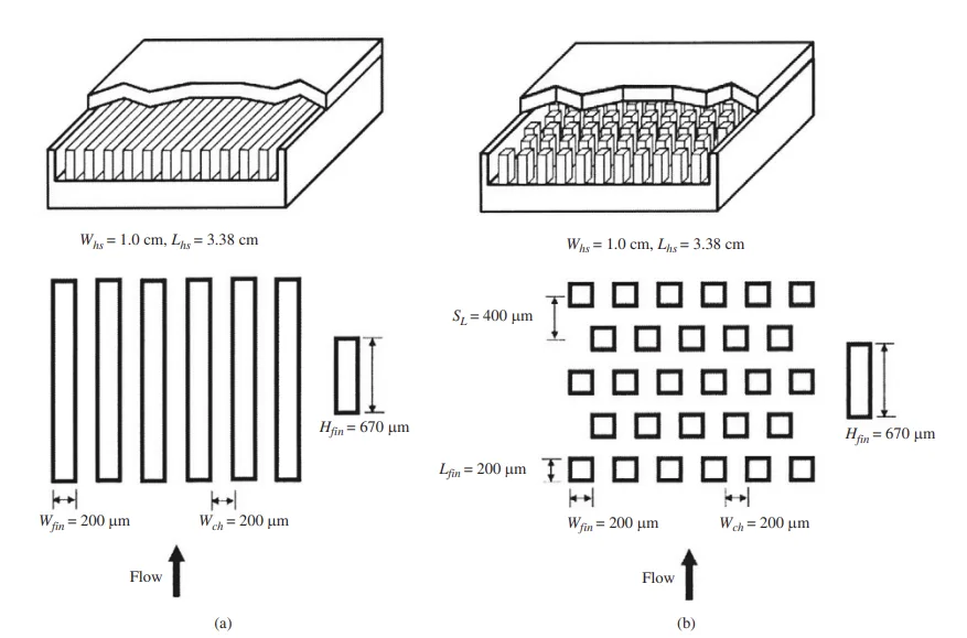
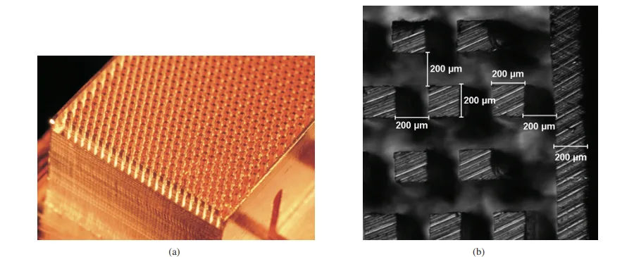
- チャネル/ピン幅200 µm、高さ670 µmの銅 (110) マイクロヒートシンク。
- マイクロピンフィンヒートシンク:1950本のマイクロピンが千鳥状に配列。
- マイクロチャネルヒートシンク:平行チャネル。
- 冷媒:単相水。
- 製造方法の焦点:マイクロエンドミル加工。
5. 主な研究結果:
- 主な研究結果:
- 熱性能: マイクロピンフィンヒートシンクは、約60g/min以上の液体流量で、マイクロチャネルヒートシンクと比較して低い対流熱抵抗を示します。60g/min未満では、マイクロチャネルヒートシンクの方が低い熱抵抗を示します。(図10. マイクロピンフィン型ヒートシンクとマイクロチャネル型ヒートシンクの平均対流熱抵抗の比較を参照)。
- 油圧性能: マイクロピンフィンヒートシンクは、試験したすべての流量範囲で、マイクロチャネルヒートシンクよりも著しく高い圧力損失を示します。(図11. マイクロピンフィン型ヒートシンクとマイクロチャネル型ヒートシンクの圧力損失の比較を参照)。
- 製造コスト: マイクロピンフィンヒートシンクは、マイクロエンドミル加工を使用して製造する場合、マイクロチャネルヒートシンクよりも約3倍高価であり、これは主に、より複雑なピンフィン形状に必要な加工時間が長いためです。加工時間が主要なコスト要因です。(図14. 1 cm x 3.38 cmの面積に対するピン/壁幅の関数としての総加工距離(工具経路)を参照)。
- 統計的/質的分析結果:
- マイクロチャネルヒートシンクの分析モデルは、予想される傾向とよく一致しています。
- 製造技術のレビュー(表I. マイクロヒートシンクの潜在的な製造方法)は、マイクロEDM、マイクロレーザー加工、およびマイクロ鋳造が大量生産に適していることを示しています。
- データ解釈:
- 高流量におけるマイクロピンフィンヒートシンクの向上した熱性能は、より曲がりくねった流れとより強い渦流による熱伝達の向上に起因すると解釈されます。
- マイクロピンフィン設計におけるより高い圧力損失は、ピンアレイからの抗力の増加によるものです。
- 加工時間の差は、工具経路の複雑さに直接関係しており、千鳥状ピンフィン形状の方が著しく長くなります。
- Figure Name List:
- Fig. 1. Structure and dimension of (a) microchannel heat sink and (b) micro-pin-fin heat sink.
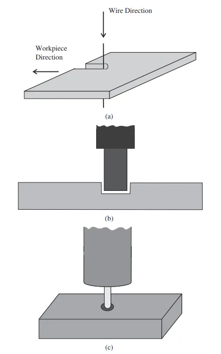
- Fig. 2. Illustrations of three electrodischarge machining techniques: (a) wire EDM, (b) die sinking, and (c) EDM milling.
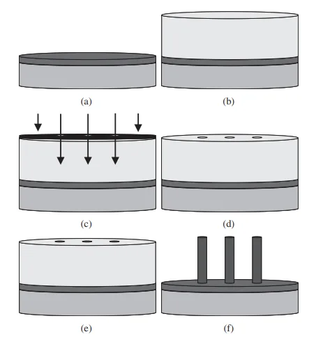
- Fig. 3. Schematic of LIGA process.
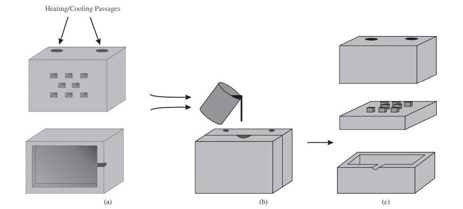
- Fig. 4. Schematic of die casting.
- Fig. 5. Schematic of extrusion process.
- Fig. 6. Schematic of micro powder injection molding.
- Fig. 7. Schematics of milling: (a) slot milling and (b) end milling.
- Fig. 8. Schematic of chip load.
- Fig. 9. Photographs of (a) copper heat sink and (b) pin fin geometry created by micro-end-milling.
- Fig. 10. Comparison of micro-pin-fin heat sink and microchannel heat sink average convection thermal resistance for (a) Tin = 30 °C and (b) Tin = 60 °C.
- Fig. 11. Comparison of micro-pin-fin heat sink and microchannel heat sink pressure drop for (a) Tin = 30 °C and (b) Tin = 60 °C.
- Fig. 12. Illustration of tool path for milling channel heat sink.
- Fig. 13. Illustration of tool path for milling staggered pin heat sink.
- Fig. 14. Total machining distance (tool path as a function of pin/wall width for a 1 cm x 3.38 cm area).
2. Research Background:
6. 結論と考察:
- 主な結果の要約:
- マイクロピンフィンヒートシンクは、高流量(>60g/min)でより優れた熱性能を提供しますが、マイクロチャネルヒートシンクと比較して圧力損失と製造コストが増加します。
- マイクロピンフィンヒートシンクのマイクロエンドミル加工コストは、加工時間が長いため、約3倍高くなります。
- 研究の学術的意義:
- マイクロピンフィン型とマイクロチャネル型ヒートシンクの熱油圧性能と製造可能性の直接的な比較を提供します。
- マイクロピンフィンアレイにおける流れの挙動と熱伝達メカニズムに関する洞察を提供します。
- マイクロエンドミル加工を使用したヒートシンクのマイクロ製造におけるコスト要因の理解に貢献します。
- 実用的な意味合い:
- 熱性能、圧力損失、およびコスト間のトレードオフを考慮して、アプリケーションの要件に基づいてヒートシンク設計を選択するための指針を提供します。
- マイクロ製造コストにおける加工時間の重要性と、プロセス改善(例:より高いスピンドル速度、高度な工具コーティング)によるコスト削減の可能性を強調します。
- マイクロピンフィンヒートシンクの大量生産のための潜在的な費用対効果の高い方法として鋳造を提案し、マイクロチャネル設計と比較した場合のコスト差を最小限に抑えます。
- 研究の限界:
- コスト分析はマイクロエンドミル加工に限定されており、他の製造方法では異なる場合があります。
- コスト比較のために一定の送り速度と工具寿命を仮定していますが、現実のシナリオでは完全に正確ではない可能性があります。
- 特定の形状に焦点を当てており、すべてのマイクロピンフィン型およびマイクロチャネル型設計に一般化できるとは限りません。
7. 今後のフォローアップ研究:
- 今後のフォローアップ研究の方向性:
- 熱性能と圧力損失を最適化するために、他のピンフィン設計(ダイヤモンド、円形、翼型)を検討します。
- 生産性の向上(より高い送り速度、スピンドル速度、高度な工具コーティング)が製造コストと設計間のコスト差の削減に及ぼす影響を調査します。
- マイクロピンフィンヒートシンクのユニットコストを削減するために、鋳造およびその他の大量生産方法に関するさらなる研究を行います。
- さらなる探求が必要な分野:
- 特定のアプリケーションおよび流れ条件に対するマイクロピンフィン形状の最適化。
- マイクロピンフィンヒートシンクの熱油圧性能を予測するための、より正確で包括的なモデルの開発。
- さまざまな製造方法と生産量を考慮した詳細なコスト分析。
8. 参考文献:
- [1] T. M. Harms, M. J. Kazmierczak, and F. M. Gerner, "Developing convective heat transfer in deep rectangular microchannels," Int. J. Heat Fluid Flow, vol. 20, no. 2, pp. 149-157, 1999.
- [2] K. Kawano, K. Minakami, H. Iwasaki, and M. Ishizuka, "Microchannel heat exchanger for cooling electrical equipment," presented at Proc. ASME Int. Mech. Eng. Congr. Expo., Fairfield, NJ, 1998.
- [3] P.-S. Lee, S. V. Garimella, and D. Liu, "Investigation of heat transfer in rectangular microchannels," Int. J. Heat Mass Transfer, vol. 48, no. 9, pp. 1688-1704, 2005.
- [4] W. Qu and I. Mudawar, "Experimental and numerical study of pressure drop and heat transfer in a single-phase microchannel heat sink," Int. J. Heat Mass Transfer, vol. 45, no. 12, pp. 2549-2565, Jun. 2002.
- [5] D. B. Tuckerman and R. F. W. Pease, "High-performance heat sinking for VLSI," IEEE Electron. Devices Lett., vol. 2, no. 5, pp. 126-129, May 1981.
- [6] A. Kosar, C.-J. Kuo, and Y. Peles, "Hydoroil-based micro-pin-fin heat sink," in Proc. 2006 ASME Int. Mech. Eng. Congr. Expo., (IMECE'06) Microelectromech. Syst., Chicago, pp. 563-570.
- [7] A. Kosar, C. Mishra, and Y. Peles, "Laminar flow across a bank of low aspect ratio micro-pin-fins," J. Fluids Eng., Trans. ASME, vol. 127, no. 3, pp. 419-430, 2005.
- [8] A. Kosar and Y. Peles, "Thermal-hydraulic performance of MEMS-based pin fin heat sink," J. Heat Transfer, vol. 128, no. 2, pp. 121-131, 2006.
- [9] Y. Peles and A. Kosar, "Convective flow of refrigerant (R-123) across a bank of micro-pin-fins," Int. J. Heat Mass Transfer, vol. 49, no. 17-18, pp. 3142-3155, 2006.
- [10] Y. Peles, A. Kosar, C. Mishra, C.-J. Kuo, and B. Schneider, "Forced convective heat transfer across a pin fin micro heat sink," Int. J. Heat Mass Transfer, vol. 48, no. 17, pp. 3615-3627, 2005.
- [11] R. S. Prasher, "Nusselt number and friction factor of staggered arrays of low aspect ratio micro-pin-fins under cross flow for water as fluid," J. Heat Transfer, vol. 129, no. 2, pp. 141-153, 2007.
- [12] A. Siu-Ho, W. Qu, and F. Pfefferkorn, "Experimental study of pressure drop and heat transfer in a single-phase micro-pin-fin heat sink," Trans. ASME. J. Electron. Packaging, vol. 129, no. 4, pp. 479-487, 2007.
- [13] W. Qu and A. Siu Ho, "Liquid single-phase flow in an array of micro-pin-fins. Part I. Heat transfer characteristics," J. Heat Transfer, vol. 130, no. 12, pp. 122402-1-122402-11, Dec. 2008.
- [14] W. Qu and A. Siu Ho, "Liquid single-phase flow in an array of micro-pin-fins. Part II: Pressure drop characteristics," J. Heat Transfer, vol. 130, no. 12, pp. 124501-1-124501-4, 2008.
- [15] J. Eugene, F. Xi, B. Tan, and B. A. Jubran, "An overview on micro-meso manufacturing techniques for micro heat exchangers for turbine blade cooling," Int. J. Manufacturing Res., vol. 3, no. 1, pp. 3-26, 2008.
- [16] K. H. Ho and S. T. Newman, "State of the art electrical discharge machining (EDM)," Int. J. Mach. Tools Manufacture, vol. 43, no. 13, pp. 1287-1300, 2003.
- [17] S. Kalpakjian and S. R. Schmid, “Advanced manufacturing processes," in Manufacturing Engineering and Technology, 5th ed. Upper Saddle River, NJ: Pearson Education, Inc., 2006, ch. 27, pp. 846-850.
- [18] C. S. Lin, Y. S. Liao, and S. T. Chen, "Development of a novel micro wire-EDM mechanism for the fabricating of micro parts," presented at Int. Conf. Advanced Manufacture, Taipei, Taiwan, 2005.
- [19] X. Cheng, "Development of ultraprecision machining system with unique wire EDM tool fabrication system for micro/nano-machining," CIRP Ann. Manufacturing Technol., vol. 57, no. 1, pp. 415-420, 2008.
- [20] D. T. Pham, S. S. Dimov, S. Bigot, A. Ivanov, and K. Popov, "Micro-EDM recent developments and research issues," presented at 14th Int. Symp. Electromach., Edinburgh, Scotland, 2004.
- [21] A. B. M. A. Asad, T. Masaki, M. Rahman, H. S. Lim, and Y. S. Wong, "Tool-based micro-machining," J. Materials Process. Tech., vol. 192-193, pp. 204-211, 2007.
- [22] M. M. Sundaram, S. Billa, and K. P. Rajurkar, "Generation of high aspect ratio micro holes by a hybrid micromachining process," presented at ASME Int. Conf. Manufacturing Sci. Eng., Atlanta, GA, 2007.
- [23] W. Ehrfeld, "Micro electro discharge machining as a technology in micromachining," in Proc. SPIE Int. Soc. Optical Eng., vol. 2879. Austin, TX, 1996, pp. 332-337.
- [24] M. Sundaram and K. Rajurkar, "Toward freeform machining by micro electro discharge machining process," Trans. North Amer. Manufacturing Res. Inst., vol. 36, pp. 381-388, 2008.
- [25] J. S. Coursey, J. Kim, and K. T. Kiger, "Spray cooling of high aspect ratio open microchannels,” J. Heat Transfer, vol. 129, no. 8, pp. 1052-1059, 2007.
- [26] M. J. Madou, "Lithography," in Fundamentals of Microfabrication, 2nd ed. Boca Raton, FL: CRC Press, 2002, ch. 1, pp. 1-10, 49-50.
- [27] R. Muwanga and I. Hassan, "Flow boiling oscillations in microchannel heat sinks," presented at 9th AIAA/ASME Joint Thermophysics Heat Transfer Conf., San Francisco, CA, 2006.
- [28] S. Stefanescu, M. Mehregany, J. Leland, and K. Yerkes, "Micro jet array heat sink for power electronics," presented at Proc. IEEE Micro Electro Mechn. Syst., Orlando, FL, 1999.
- [29] X. Wei, C. H. Lee, Z. Jiang, and K. Jiang, "Thick photoresists for electroforming metallic microcomponents," J. Mech. Eng. Sci., vol. 222, no. 1, pp. 37-42, 2008.
- [30] C. H. Ho, K. P. Chin, C. R. Yang, H. M. Wu, and S. L. Chen, "Ultrathick SU-8 mold formation and removal, and its application to the fabrication of LIGA-like micromotors with embedded roots," Sensors and Actuators A (Physical), vol. 102, no. 1-2, pp. 130–138, 2002.
- [31] H. Guckel, "High-aspect-ratio micromachining via deep X-ray lithography," Proc. IEEE, vol. 86, no. 8, pp. 1586-1593, Aug. 1998.
- [32] J. Li, D. Chen, J. Zhang, J. Liu, and J. Zhu, "Indirect removal of SU-8 photoresist using PDMS technique,” Sensors and Actuators A (Physical), vol. 125, no. 2, pp. 586-589, 2006.
- [33] L. T. Romankiw, "Path: From electroplating through lithographic masks in electronics to LIGA in MEMS," Electrochimica Acta, vol. 42, no. 20-22, pp. 2985-3005, 1997.
- [34] R. K. Kupka, F. Bouamrane, C. Cremers, and S. Megtert, "Microfabrication: LIGA-X and applications," Appl. Surface Sci., vol. 164, no. 1-4, pp. 97-110, 2000.
- [35] R. Engelke, "Complete 3-D UV microfabrication technology on strongly sloping topography substrates using epoxy photoresist SU-8," Microelectron. Eng., vol. 73-74, pp. 456-462, 2004.
- [36] A. J. Pang, "Design, manufacture and testing of a low-cost microchannel cooling device," presented at 6th Electron. Packaging Technol. Conf., Piscataway, NJ, 2004.
- [37] L. S. Stephens, K. W. Kelly, D. Kountouris, and J. McLean, "A pin fin microheat sink for cooling macroscale conformal surfaces under the influence of thrust and frictional forces," J. Microelectromech. Syst., vol. 10, no. 2, pp. 222-231, 2001.
- [38] G. Baumeister, R. Ruprecht, and J. Hausselt, "Microcasting of parts made of metal alloys," Microsyst. Technol., vol. 10, no. 3, pp. 261-264, 2004.
- [39] B. S. Li, M. X. Ren, C. Yang, and H. Z. Fu, "Microstructure of Zn-Al4 alloy microcastings by micro precision casting based on metal mold," Trans. Nonferrous Metals Soc. China, vol. 18, no. 2, pp. 327-332, 2008.
- [40] G. Baumeister, K. Mueller, R. Ruprecht, and J. Hausselt, "Production of metallic high aspect ratio microstructures by microcasting," Microsyst. Technol., vol. 8, no. 2-3, pp. 105-108, 2002.
- [41] G. Baumeister, R. Ruprecht, and J. Hausselt, "Replication of LIGA structures using microcasting," Microsyst. Technol., vol. 10, no. 6, pp. 484-488, 2004.
- [42] S. Chung, S. Park, H. Jeong, I. Lee, and D. Cho, "Replication techniques for a metal microcomponent having real 3-D shape by microcasting process," Microsyst. Technol., vol. 11, no. 6, pp. 424-437, 2005.
- [43] J. Cao and N. Krishnan, "Recent advances in microforming: Science, technology and applications," in Proc. Materials Sci. Technol. 2005, Pittsburgh, PA, pp. 225-234.
- [44] N. Krishnan, J. Cao, and K. Dohda, "Study of the size effects on friction conditions in microextrusion Part I: Microextrusion experiments and analysis," J. Manufacturing Sci. Eng., Trans. ASME, vol. 129, no. 4, pp. 669-676, 2007.
- [45] M. Geiger, M. Kleiner, R. Eckstein, N. Tiesler, and U. Engel, "Micro-forming," CIRP Ann. Manufacturing Technol., vol. 50, no. 2, pp. 445-462, 2001.
- [46] N. Krishnan, J. Cao, B. Kinsey, S. A. Paraslz, and M. Li, "Investigation of deformation characteristics of micro-pins fabricated using microextrusion," presented at ASME Int. Mech. Eng. Congr. Expo., Orlando, FL, 2005.
- [47] S. G. Li, "Dimensional variation in production of high-aspect-ratio micro-pillars array by micro powder injection molding," Appl. Physics A-Materials Sci. Process., vol. 89, no. 3, pp. 721-728, 2007.
- [48] G. Fu, "Injection molding, debinding and sintering of 316L stainless steel microstructures," Appl. Physics a-Materials Sci. Process., vol. 81, no. 3, pp. 495-500, 2005.
- [49] J. Chen, J. Yang, and T. Zuo, "Micro fabrication with selective laser micro sintering," presented at 1st IEEE Int. Conf. Nano Micro Eng. Molecular Syst., Zhuhai, China, 2006.
- [50] X. Li, H. Choi, and Y. Yang, "Micro rapid prototyping system for micro components," Thin Solid Films, vol. 420-421, pp. 515-523, 2002.
- [51] Y. Jeon, and F. Pfefferkorn, "Effect of laser preheating the workpiece on micro-end-milling of metals," presented at Proc. ASME Int. Mech. Eng. Congr. Expo., Orlando, FL, 2005.
- [52] E. Oberg, F. D. Jones, H. L. Horton, and H. H. Ryffel, "Aluminum alloys," in Machinery's Handbook, 28th ed. New York: Industrial Press, 2004, p. 1014.
- [53] S. Jahanmir, "Ultra-high-speed micro-milling spindle," Poster MSECICMP2008-72573 presented at ASME Int. Conf. Manufacturing Sci. Eng., Evanston, IL, Oct. 7-10, 2008.
- [54] T. Ozel and T. Altan, "Process simulation using finite element method prediction of cutting forces, tool stresses and temperatures in high-speed flat end milling," Int. J. Mach. Tools Manufacture, vol. 40, no. 5, pp. 713-738, 2000.
- [55] M. P. Vogler, R. E. DeVor, and S. G. Kapoor, "On the modeling and analysis of machining performance in micro-end-milling, Part I: Surface generation," Trans. ASME. J. Manufacturing Sci. Eng., vol. 126, no. 4, pp. 685-694, 2004.
- [56] R. D. Blevins, Applied Fluid Dynamics Handbook, 1st ed. New York: Van Nostrand Reinhold Company, 1984, ch. 6, pp. 38-123.
- [57] R. K. Shah and A. L. London, Laminar Flow Forced Convection in Ducts: A Source Book for Compact Heat Exchanger Analytical Data, Supl. 1, New York: Academic Press, 1978, ch. 7, pp. 196-222.
9. 著作権:
- この資料は、「Benjamin A. Jasperson, Yongho Jeon, Kevin T. Turner, Frank E. Pfefferkorn, and Weilin Qu」の論文:「Comparison of Micro-Pin-Fin and Microchannel Heat Sinks Considering Thermal-Hydraulic Performance and Manufacturability」に基づいて要約されています。
- 論文ソース:10.1109/TCAPT.2009.2023980
この資料は上記の論文に基づいて要約されており、商業目的での無断使用は禁止されています。
Copyright © 2025 CASTMAN. All rights reserved.