1.概要:
- タイトル: 三相75kWブラシレス直流電動機による電気自動車向け電力段設計、損失計算、冷却技術、および比較
- 著者: Ali Bahadir, Omer Aydogdu, Elif Bahadir
- 発行年: 2024年
- 発行誌/学会: Applied Sciences
- キーワード: ブラシレス直流電動機、電気自動車(EV)、電力段、冷却システム、損失
2. 研究背景:
気候変動によるCO2、SO2排出量の削減が喫緊の課題となっており、そのため電気自動車の効率向上は極めて重要です。ブラシレス直流(BLDC)モーターは高出力密度、高効率、高信頼性から電気自動車に広く採用されていますが、内部発熱が大きく、熱放散が非効率であるため、信頼性と寿命が制限されています。したがって、電気モーターの損失を低減し、効率を向上させる研究が不可欠です。従来の研究はバッテリーまたはモーターの冷却に焦点を当てており、冷却システム自体のエネルギー消費量を考慮していなかったという限界がありました。
3. 研究目的と研究課題:
- 研究目的: 75kW BLDCモーターのための電力段設計、損失計算、冷却システム設計を行い、それらを比較することで電気自動車の効率向上を目指します。
- 主要な研究課題: 3つの異なる電力段設計と冷却システム(空冷、ファンアシスト空冷、液冷)の性能をどのように比較できるか?各冷却システムの効率と損失をどのように定量化できるか?
- 研究仮説: 液冷システムは、空冷およびファンアシスト空冷システムよりも効率的である。

4. 研究方法:
- 研究設計: MATLAB/Simulinkを用いて電気自動車モデルを構築し、75kW BLDCモーターのための3つの異なる電力段設計を行いました。3つの異なる冷却システムを設計し、その性能を比較分析しました。
- データ収集方法: シミュレーションと実験によりデータを取得しました。損失計算にはIGBTのデータシートを使用しました。冷却システムの性能は温度測定によって評価しました。
- 分析方法: 損失計算は、スイッチング損失と導通損失を個別に計算し、それらを合計することで行いました。冷却システムの性能比較は、温度値と効率に基づいて行いました。
- 研究対象と範囲: 75kW BLDCモーターのための3つの電力段設計と3つの冷却システム(空冷、ファンアシスト空冷、液冷)が研究対象です。
5. 主要な研究結果:
- 主要な発見: 3つの冷却システムのうち、液冷システムが最も効率的で、空冷システムが最も効率が低いことがわかりました。IGBTモジュールの配置間隔が熱抵抗に影響を与えることを確認しました。
- 量的/質的分析結果: 3つの電力システムの総損失はそれぞれ約2.3kWと計算され、システム効率は約97%と計算されました。液冷システムは出力温度を20.5℃に維持し、システムから4.5℃の温度を除去しました。空冷システムではIGBT温度が96℃に上昇しましたが、20mmの間隔で配置した場合には90℃に低下しました。
- データ解釈: 液冷システムは効率的な熱除去によってシステム温度を低下させ、効率を向上させます。IGBTモジュールの配置間隔は熱伝達に影響を与えるため、最適化が必要です。サンドイッチバスバー設計は寄生インダクタンスを低減し、システムサイズを縮小する上で効果的です。
- 図表リストと説明: 本論文に示されている図表は、電気自動車モデル、電力段設計、冷却システム設計、損失計算、実験結果などを視覚的に示しています。
- Figure 1: Force components acting on the vehicle.
- Figure 2: Vehicle general model.
- Figure 3: Internal structure block of the general vehicle model.
- Figure 4: BLDC motor Simulink model.
- Figure 5: Load model.
- Figure 6: IGBT modules selected for BLDC motor driver.
- Figure 7: Thermal resistance of the system with cooler.
- Figure 8: Placement of IGBT modules in the heatsink.
- Figure 9: Sample IGBT (20 mm) thermal distribution.
- Figure 10: Sample IGBT (0 mm) thermal analysis.
- Figure 11: Liquid cooler module top and profile view.
- Figure 12: Liquid cooling module top view.
- Figure 13: Liquid cooling module with IGBTs in place.
- Figure 14: (a) Axial-flow fan; (b) Radial-flow fan; (c) Cross-flow fan.
- Figure 15: Sandwich busbar design.
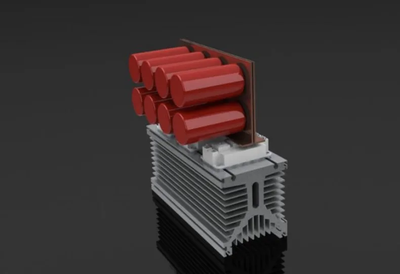
- Figure 16: DC-Bus IGBT heatsink and capacitance.
- Figure 17: IGBT module design on a fluid cooling system.
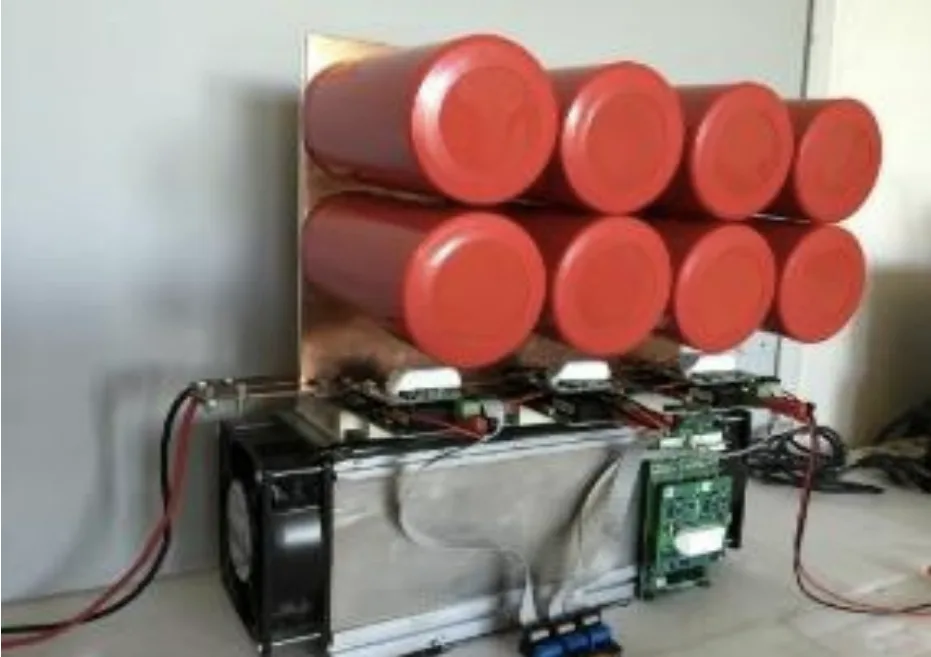
- Figure 18: Original 75 kW fan-assisted natural-air cooled three-phase inverter circuit.
- Figure 19: Original 75 kW liquid-cooled three-phase inverter circuit.
- Figure 20: Original three-phase 75 kW liquid cooled inverter circuit with six IGBT modules.
- Figure 21: Three-dimensional design visuals of the cooling module from the front, top and side.
- Figure 22: SKiM459GD12E4 IGBT module, adapter circuit, and IGBT driver assembly.
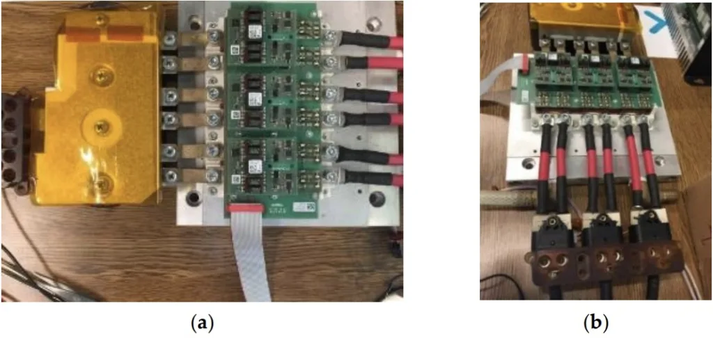
- Figure 23: (a) Original three-phase 75 kW liquid cooled inverter circuit with six IGBT modules; (b) Different angle view of Figure 23(a).
- Figure 24: The BLDC motor's rapid control prototyping block diagram with dSpace Micro-Auto Box.
- Figure 25: System engine-generator test platform with DS1401 dSpace Micro-Auto Box.
- Figure 26: BLDC motor phase currents and interphase voltages.
- Remember that this list is based on the extracted text and might not be entirely complete or perfectly accurate. Always refer to the original paper for definitive information.


6.結論と考察:
3つの異なる電力段設計と3つの冷却システムを比較分析した結果、液冷システムが最も効率的であることが示されました。本研究は、電気自動車の効率向上のための電力システムと冷却システム設計に対する重要な示唆を与えます。サンドイッチバスバー設計はシステムサイズと損失を低減する上で効果的です。IGBTモジュールの配置間隔の最適化により熱抵抗を低減できます。
研究の限界: 本研究はシミュレーションと実験室環境下で行われたものであり、実際の走行環境での性能は異なる可能性があります。
7. 今後の研究:
実際の走行環境での性能検証、様々な走行条件下での冷却システム性能の分析、さらに効率的な冷却システム設計と制御アルゴリズムの開発などが今後の研究課題です。
8. 参考文献要約:
- Tutelea, L.; Boldea, I. Optimal Design of Residential Brushless D.C. Permanent Magnet Motors with FEM Validation. In
Proceedings of the Aegean Conference on Electric Machines, Power Electronics and Electromotion (ACEMP ‘07), Bodrum, Turkey,
10–12 September 2007; pp. 435–439. - Zarko, D.; Ban, D.; Lipo, T.A. Analytical Solution for Cogging Torque in Surface Permanent-Magnet Motors Using Conformal
Mapping. IEEE Trans. Magn. 2007, 44, 52–64. [CrossRef] - Ustun, O.; Yilmaz, M.; Gokce, C.; Karakaya, U.; Tuncay, R.N. Energy Management Method for Solar Race Car Design and
Application. In Proceedings of the IEEE International Electric Machines and Drives Conference, Miami, FL, USA, 3–6 May 2009;
pp. 804–811. - Markovic, M.; Hodder, A.; Perriard, Y. An Analytical Determination of The Torque–Speed and Efficiency–Speed Characteristics
of a BLDC Motor. In Proceedings of the Energy Conversion Congress and Exposition (ECCE 2009), San Jose, CA, USA, 20–24
September 2009; pp. 168–172. - Zhao, L.; Ham, C.; Zheng, L.; Wu, T.; Sundaram, K.; Kapat, J.; Chow, L. A Highly Efficient 200,000 Rpm Permanent Magnet Motor
System. IEEE Trans. Magn. 2007, 43, 2528–2530. [CrossRef] - Tuncay, R.N.; Üstün, O.; Yılmaz, M.; Gokce, C.; Karakaya, U. Design and Implementation of An Electric Drive System for In-Wheel
Motor Electric Vehicle Applications. In Proceedings of the 7th IEEE Vehicle Power and Propulsion Conference (VPPC’11), Chicago,
IL, USA, 6–9 September 2011; pp. 1–6. - Bahadir, A.; Aydogdu, O. Modeling of a brushless dc motor driven electric vehicle and its pid-fuzzy control with dSPACE. Sigma
J. Eng. Nat. Sci. 2023, 41, 156–177. [CrossRef] - Wu, W.; Wang, S.; Wu, W.; Chen, K.; Hong, S.; Lai, Y. A critical review of battery thermal performance and liquid based battery
thermal management. Energy Convers. Manag. 2019, 182, 262–281. [CrossRef] - Arasu, M.; Ahmed, Q.; Rizzoni, G. Optimizing battery cooling system for a range extended electric truck. SAE Tech. Pap. 2019,
2019, 158. - Kong, D.; Peng, R.; Ping, P.; Du, J.; Chen, G.; Wen, J. A novel battery thermal management system coupling with PCM and
optimized controllable liquid cooling for different ambient temperatures. Energy Convers. Manag. 2020, 204, 112280. [CrossRef] - Davin, T.; Pellé, J.; Harmand, S.; Yu, R. Experimental study of oil cooling systems for electric motors. Appl. Therm. Eng. 2015,
75, 1–13. [CrossRef] - Fang, G.; Yuan, W.; Yan, Z.; Sun, Y.; Tang, Y. Thermal management integrated with three-dimensional heat pipes for air-cooled
permanent magnet synchronous motor. Appl. Therm. Eng. 2019, 152, 594–604. [CrossRef] - Huang, J.; Naini, S.S.; Miller, R.; Rizzo, D.; Sebeck, K.; Shurin, S.; Wagner, J. A Hybrid Electric Vehicle Motor Cooling System—
Design, Model, and Control. IEEE Trans. Veh. Technol. 2019, 68, 4467–4478. [CrossRef] - Lombardi, S.; Villani, M.; Chiappini, D.; Tribioli, L. Cooling System Energy Consumption Reduction through a Novel All-Electric
Powertrain Traction Module and Control Optimization. Energies 2021, 14, 33. [CrossRef] - Bhosale, P.; Hermwille, M. Connection of Gate Drivers to IGBT and Controller. Semikron Application Note AN-7002. 5 September
- Available online: www.Semikron.com/Application/DriverConnection (accessed on 18 January 2024).
- Daucher, C.; Wintrich, A.; Pluschke, N. SEMIKRON Application Manual—Power Modules; 4 April 2006 Rev1; SEMIKRON:
Nuremberg, Germany, 2006. - Wintrich, A.; Nicolai, U.; Tursky, W.; Reimann, T. SEMIKRON Application Manual—Power Semiconductors, 2nd ed.; ISLE Verlag,
SEMIKRON International: Nuremberg, Germany, 2015; pp. 299–302, ISBN 978-3-938843-83-3. - Pluschke, N. Application Manual Power Modules; SEMIKRON: Nuremberg, Germany, 2006.
著作権:
この要約は、Ali Bahadir、Omer Aydogdu、Elif Bahadirによる論文「Three-Phase 75 kW Brushless Direct Current Motor for Electric Vehicles: Different Power Stage Design, Calculation of Losses, Cooling Techniques, and Comparison」に基づいて作成されました。
DOI URL: https://doi.org/10.3390/app14041365
この資料は上記の論文に基づいて要約されており、商業目的での無断使用を禁じます。
Copyright © 2025 CASTMAN. All rights reserved.