本技術要約は、Randeep Singh氏がRMIT大学で発表した学術論文「Thermal Control of High-Powered Desktop and Laptop Microprocessors Using Two-Phase and Single-Phase Loop Cooling Systems」(2006年3月)に基づいています。この資料は、HPDCの専門家のために、CASTMANの専門家がGemini、ChatGPT、GrokなどのLLM AIの支援を受けて分析・要約したものです。
キーワード
- 主要キーワード: 二相ループ冷却システム
- 副次キーワード: 小型ループヒートパイプ (mLHP), マイクロプロセッサ熱制御, 単相液体冷却, マイクロチャネルヒートシンク, 焼結多孔質ヒートシンク, キャピラリーポンプドループ (CPL), 高熱流束冷却
エグゼクティブサマリー
- 課題: デスクトップ(80-130W)およびノートPC(25-50W)のマイクロプロセッサの電力密度が急激に増加し、ヒートパイプやベイパーチャンバーといった従来の冷却技術が限界に達しています。将来の電子システムには、より高度な熱管理ソリューションが不可欠です。
- 手法: 本研究では、受動的な二相熱伝達(小型ループヒートパイプ、mLHP)と能動的な単相液体冷却(マイクロチャネルおよび焼結多孔質ヒートシンクを使用)の両方に基づいたさまざまな熱設計を開発し、その特性を評価しました。
- 重要なブレークスルー: 二相冷却ユニットは、ノートPCのような小型デバイスにおける高熱流束(最大70 W/cm²)に対して非常に信頼性の高い受動的ソリューションであることが証明されました。一方、高性能デスクトップの極端な熱流束(最大400 W/cm²)に対しては、能動的な単相液体冷却システムがより効果的ですが、構造が複雑になります。
- 結論: 受動的な二相冷却と能動的な単相冷却の選択は画一的なものではなく、用途特有の熱流束、スペースの制約、信頼性要件に大きく依存します。
課題:なぜこの研究がHPDC専門家にとって重要なのか
電子機器の処理能力が飛躍的に向上するにつれて、発生する廃熱も増大しています。現在、デスクトップやサーバーのCPUは80〜130W、ノートPCは25〜50Wの熱を放出しており、これらの数値は今後も上昇の一途をたどります。この熱問題は、チップセット自体の設置面積が縮小することでさらに深刻化し、70 W/cm²を超える極端な熱流束につながる可能性があります。
エンジニアや設計者にとって、チップの表面温度を100°C未満に維持することは、信頼性のために譲れない要件です。標準的なヒートパイプやベイパーチャンバーを含む従来の冷却方法では、これらの高出力システムの将来の熱需要を満たすことができないと予想されています。これにより、小型の電子機器に統合できる、革新的で信頼性が高く、強力な熱制御技術が緊急に必要とされています。本研究は、次世代の受動的および能動的ループ冷却システムを探求することで、まさにこの問題に取り組んでいます。
アプローチ:研究方法論の解明
この喫緊の熱問題に対する解決策を見出すため、研究者は2つの異なる原理に基づいた複数の先進的な冷却プロトタイプを開発し、その特性を評価しました。
- 二相冷却システム(受動型): この研究では、受動的に作動する小型ループヒートパイプ(mLHP)の研究用プロトタイプの開発と試験に焦点を当てました。これらのデバイスは、ウィック構造内の毛細管力を利用して作動流体を循環させ、能動的なポンプなしで蒸発・凝縮サイクルを通じて熱を伝達します。プロトタイプには、平坦なディスク型蒸発器と革新的な薄型矩形蒸発器を備えたmLHPが含まれていました。
- 単相液体冷却システム(能動型): さらに高く、より集中した熱流束に対応するため、研究では能動的な液体冷却を探求しました。これには、マイクロチャネルや焼結多孔質媒体を含む革新的な微細構造を持つヒートシンクの開発が含まれます。これらのシステムは、ポンプを使用して能動的に液体冷却材を循環させ、はるかに高い熱除去能力の可能性を提供します。
これらの異なるシステムを構築、試験、比較することにより、本研究は、さまざまな高密度マイクロプロセッサ用途に対するそれぞれの性能、能力、および適合性に関する包括的な分析を提供します。
ブレークスルー:主要な発見とデータ
この広範な調査により、次世代冷却技術の性能と応用に関する重要な洞察が得られました。
- 発見1:二相mLHPは小型・高熱流束用途で卓越した性能を発揮。 開発された平坦なディスク型蒸発器を備えた小型ループヒートパイプ(mLHP)は、70 W/cm²もの高熱流束を除去し、その熱を150 mm以上伝達できることが証明され、ノートPCのマイクロプロセッサにとって非常に信頼性が高く、多目的なソリューションであることが示されました。
- 発見2:単相システムは極端な熱流束を克服。 極端な電力密度を持つデスクトップおよびサーバー用途では、単相液体冷却システムが優れた性能を発揮しました。微細構造(マイクロチャネルや焼結多孔質媒体など)を持つヒートシンクは、400 W/cm²もの集中した熱流束を処理できることが示されました。
- 発見3:明確な性能のトレードオフが存在。 比較研究(第9章)により、明確な区別が明らかになりました。二相の受動的システムは、低〜中程度の高熱流束に対して非常に信頼性が高く効率的です。しかし、極端な熱負荷では性能が低下し、その場合は複雑でポンプが必要な単相の能動的システムがより効果的です(Figure 9.12参照)。
- 発見4:蒸発器の設計が小型化の鍵。 この研究では、補償チャンバーを側面に再配置することで、厚さわずか5mmの平坦な矩形蒸発器を持つmLHPを成功裏に開発しました。これにより大幅な薄型化が達成されましたが、10mmのディスク型設計と比較してわずかな性能のトレードオフが伴い、小型化における重要な設計上の考慮事項を浮き彫りにしました(Figure 6.13)。
- 発見5:材料の適合性と純度が最も重要。 この研究では、非凝縮性ガス(NCG)の発生が性能を低下させ、起動時間を増加させる可能性があることを確認しました。適切な洗浄手順と作動流体の脱気は、長期的で信頼性の高い動作を保証するために不可欠です(Figure 5.37, Figure 5.41)。
貴社の製品開発への実践的示唆
この論文は電子機器の冷却に焦点を当てていますが、先進的な熱管理の原則は普遍的に適用可能です。ダイカスト製筐体に収められる可能性のある高性能コンポーネントを扱うエンジニアにとって、これらの知見は貴重な洞察を提供します。
- 部品およびシステム設計者へ: この研究は、適切な先進冷却技術を選択するためのデータ駆動型のフレームワークを提供します。第9章の比較研究は、 значительнаяが極端ではない熱負荷を持つ高信頼性アプリケーション(ノートPCやモバイルデバイスなど)には、受動的な二相mLHPが優れた選択肢であることを明確に示しています。最大熱除去が最優先されるシステム(高性能サーバーなど)には、能動的な単相液体冷却が優れています。
- 品質および信頼性エンジニアへ: 非凝縮性ガス(NCG)の発生に関する知見(第5.9章)は、あらゆる密閉型熱管理システムにおける材料の適合性と製造上の清浄度の重要性を強調しています。この研究は、微量の不純物でさえも時間とともに性能低下につながる可能性があることを示しており、長寿命製品にとって極めて重要な教訓です。
- 研究開発およびイノベーションチームへ: 厚さ5mmの平坦な矩形蒸発器の斬新な設計(第6章)は、強力な熱ソリューションを小型化するための実用的な道筋を示しています。主要コンポーネントを再配置して全体の厚さを減らすというこのコンセプトは、熱管理を小型製品アセンブリに直接統合する際のイノベーションにインスピレーションを与えることができます。
論文詳細
Thermal Control of High-Powered Desktop and Laptop Microprocessors Using Two-Phase and Single-Phase Loop Cooling Systems
1. 概要:
- タイトル: Thermal Control of High-Powered Desktop and Laptop Microprocessors Using Two-Phase and Single-Phase Loop Cooling Systems
- 著者: Randeep Singh
- 発行年: 2006年3月
- 発行機関: RMIT University (博士論文)
- キーワード: 二相冷却, 単相冷却, ループヒートパイプ, マイクロチャネルヒートシンク, 焼結多孔質ヒートシンク, 熱制御, マイクロプロセッサ
2. 要旨:
ハイエンドでコンパクトなコンピュータの開発は、そのマイクロプロセッサの放熱要件を著しく増大させました。現在、デスクトップおよびサーバーコンピュータのCPUによる廃熱は80〜130W、ノートPCは25〜50Wです。新しいシステムでは、デスクトップで最大200W、ノートPCで約70Wの熱出力を持つものがすでに構築されています。同時に、チップセットの発熱面積は1〜4cm²と小さくなっています。この問題は、利用可能なスペースが限られていることと、チップの表面温度を100℃未満に維持するという制約の両方によってさらに複雑化しています。ヒートパイプやベイパーチャンバーのような従来の二相技術や、現在の単相冷却システムの設計では、これらの将来のコンピュータシステムの熱需要を満たすことができないと予想されています。この問題の解決策を見出す目的で、二相および単相の熱伝達に基づいた異なる熱設計が開発され、高密度マイクロプロセッサの熱制御のために特性評価されました。二相技術の分野では、厚さが5mmまたは10mmと小さく、70W/cm²もの高熱流束を放散できる、毛細管駆動の受動的に動作するループヒートパイプの試作品が2つ設計・試験されました。これらのデバイスは、ノートPCのマイクロプロセッサの熱需要に非常によく応えました。単相冷却システムの熱特性は、400W/cm²もの集中した熱流束を処理する目的で強化されました。これは、マイクロチャネルや焼結多孔質媒体を含む革新的な微細構造を持つヒートシンクを開発することによって可能になりました。本研究の成果として、二相冷却ユニットは、高熱流束と熱デバイスを収容するための限られたスペースを持つノートPCのマイクロプロセッサの冷却に対して、非常に信頼性の高い熱ソリューションを提供すると結論付けられます。しかし、受動的デバイスの熱性能は、非常に高い熱流束では制限されます。したがって、将来の高出力電子システムの効果的な管理のためには、冷却技術をさらに探求する必要があります。液体冷却システムは非常に高い熱流束を効果的に処理できますが、構造的に複雑であり、システム内に能動的なコンポーネント(ポンプなど)が必要で、その動作にも電力を必要とするため、信頼性が低いという問題があります。
3. 緒言:
熱制御は電子機器の普遍的なニーズです。論文の第1章で詳述されているように、ノートPCとデスクトップの両方でマイクロプロセッサからの放熱が増加しているため、従来の冷却方法では不十分になっています。単純なデバイスは自然対流に依存しますが、高性能コンピュータには高度な熱ソリューションが必要です。ヒートパイプやベイパーチャンバーは効果的でしたが、将来の電力密度はより高性能なシステムを要求しています。これにより、本研究では次世代コンピュータの熱需要に対応するために、革新的な二相ループヒートパイプや微細構造を持つ強化された単相液体冷却システムの開発が進められました。
4. 研究概要:
研究トピックの背景:
本研究は、現代のコンピュータにおける熱管理という重要な課題に取り組んでいます。マイクロプロセッサの電力密度の増加とサイズの縮小により、従来の空冷、ヒートパイプ、ベイパーチャンバーを超えるソリューションが求められています。
従来の研究状況:
従来の研究では、主に航空宇宙分野向けにループヒートパイプ(LHP)やキャピラリーポンプドループ(CPL)が堅牢な二相システムとして、また高熱流束アプリケーション向けにマイクロチャネルを用いた単相液体冷却が確立されていました。しかし、商用電子機器向けの小型化・低コスト化されたバージョン、特に同様の制約下での性能比較については、さらなる調査が必要でした。
研究の目的:
主な目的は、ノートPCおよびデスクトップマイクロプロセッサの高熱流束を管理するために、二相冷却と単相冷却の両方に基づいたさまざまな熱ソリューションを調査、設計、開発することでした。これには、ノートPC向けの小型LHP(mLHP)プロトタイプの開発と、デスクトップ向けの微細構造ヒートシンクの開発、およびそれらの性能比較が含まれます。
中核研究:
研究の中核は、以下の2つの主要な冷却システムの設計、製造、および実験的試験を含んでいました。
- 異なる平坦な蒸発器設計(10mmディスク型および5mm矩形型)を持つ二相小型ループヒートパイプ(mLHP)。
- マイクロチャネルヒートシンクおよび焼結多孔質ヒートシンクを使用した単相液体冷却システム。
その後、単一および複数の熱源に対して、二相ヒートパイプモジュールと単相マイクロチャネルシステムの性能を比較するための研究が行われました。
5. 研究方法論
研究設計:
本研究は一連の実験的調査として設計されました。各冷却システム(ディスク型蒸発器mLHP、矩形型蒸発器mLHP、マイクロチャネルヒートシンク、焼結多孔質ヒートシンク)のプロトタイプが設計・製造されました。性能予測のためにLHPの理論モデルも開発されました。
データ収集および分析方法:
各プロトタイプのための実験用テストベッドが構築されました。データは、さまざまな地点に設置されたT型熱電対、圧力トランスデューサ、および熱負荷を制御・測定するためのデジタル電力計を使用して収集されました。データ収集システムは5〜10秒ごとに温度を記録しました。熱性能は、蒸発器温度、熱抵抗(蒸発器、全体)、および熱負荷と冷却材流量の関数としての熱伝達係数などの主要な指標を計算することによって分析されました。
研究トピックと範囲:
本研究は以下のいくつかの主要なトピックをカバーしています。
- ノートPC冷却用の二相mLHPの設計と特性評価(最大70W)。
- デスクトップ冷却用の単相液体冷却システムの設計と特性評価(最大200W、>400W/cm²)。
- mLHPにおける起動現象、作動流体量の影響、傾斜の影響、および非凝縮性ガス(NCG)の発生に関する分析。
- 単一および複数の熱源に対する二相冷却と単相冷却の直接的な性能比較。
6. 主要な結果:
主要な結果:
- 小型ループヒートパイプ(mLHP)は、ノートPCの高熱流束チップセット(最大70 W/cm²)を冷却するための効果的で信頼性の高い受動的技術である。
- 微細構造(マイクロチャネル、焼結多孔質ウィック)を用いた液体冷却は、高出力デスクトップシステムの極端な熱流束(最大408 W/cm²で試験)に対する実行可能なアプローチである。
- 二相毛細管駆動システムは、能動部品(ポンプ)がないため信頼性が高いが、単相システムは超高熱流束に対してより良い熱制御を提供する。
- 補償チャンバーの再配置など、斬新な設計コンセプトを用いることで、mLHP蒸発器の厚さを(10mmから5mmへ)スケールダウンすることが可能である。
- mLHPの動作特性は、ウィックの特性(材料、孔径、多孔性)と作動流体の充填量に大きく依存する。二峰性多孔質ウィックは、単峰性多孔質ウィックよりも優れた性能を示す。
- 熱抵抗と圧力損失の両面において、マイクロチャネルヒートシンクの熱性能は、焼結多孔質ヒートシンクのそれよりも優れていることがわかった。
図のリスト:
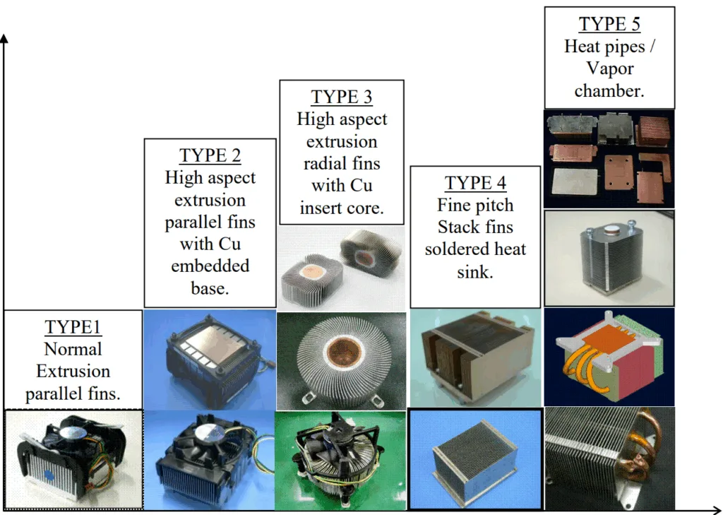
- Figure 1.1 Trends in Thermal Solutions for Laptop PCs
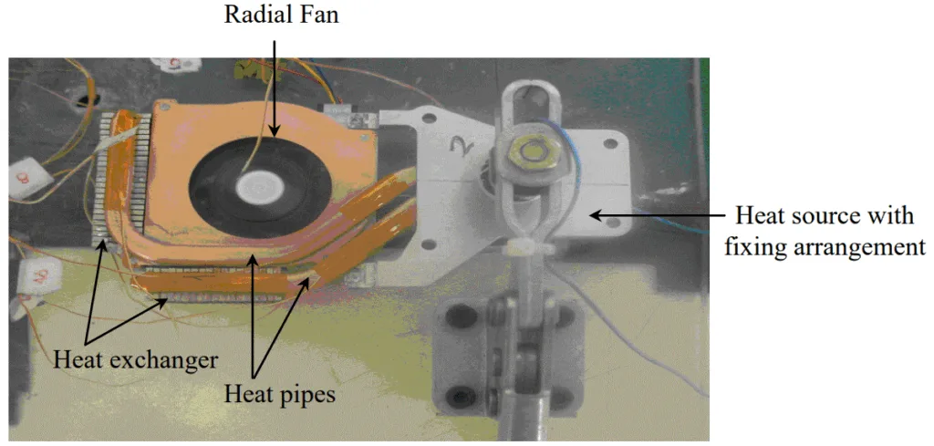
- Figure 1.2 Hybrid thermal control system for laptop microprocessors.
- Figure 1.3 Remote Heat Exchanger for cooling laptop microprocessors.
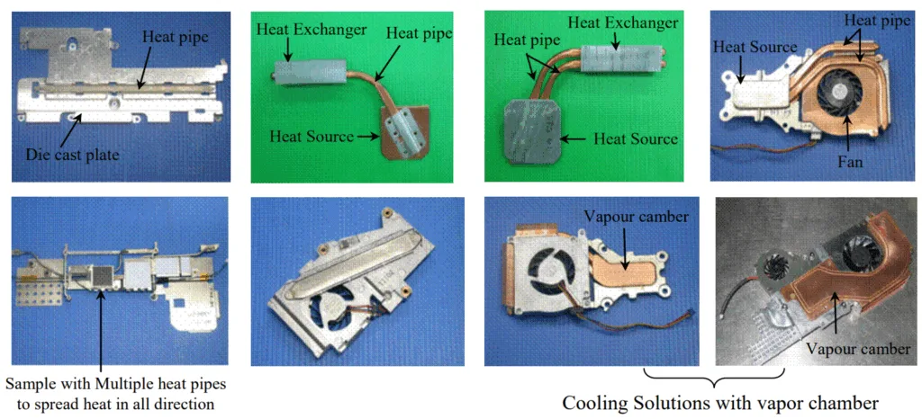
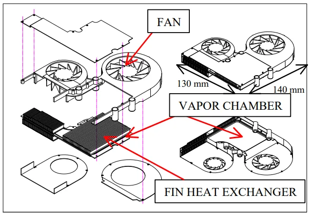
- Figure 1.4 Different designs of vapour chamber used for laptop cooling
- Figure 1.5 Thermal control system with vapour chamber for laptop cooling
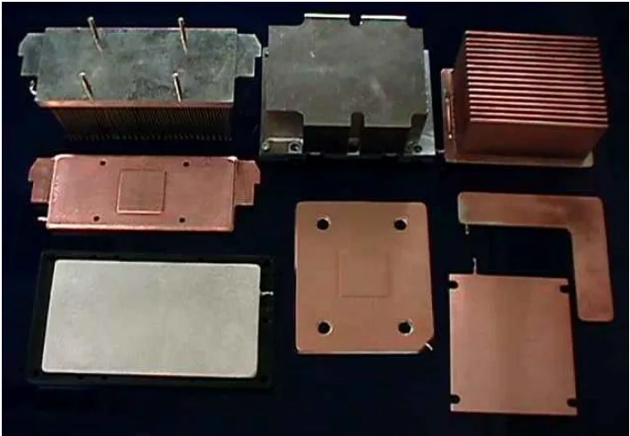
- Figure 1.6 Different Types of Thermal Solution for Desktop Computer Cooling
- Figure 1.7 Thermal Solution Trends
- Figure 2.1 Conventional Capillary Driven Heat Pipe
- Figure 2.2 Arterial Heat Pipes
- Figure 2.3 Separated lines heat pipe
- Figure 2.4 Loop Scheme
- Figure 2.5 Loop Heat Pipe (LHP)
- Figure 2.6 Capillary Pumped Loop (CPL)
- Figure 2.7 Schematic of Loop Heat Pipe
- Figure 2.8 Scheme of organisation of evaporation zone by the principle of an inverted meniscus
- Figure 2.9 Available cooling space inside the laptop computer
- Figure 2.10 Different variants of LHP condenser
- Figure 2.11 Schematic of a Microchannel Heat Sink
- Figure 2.12 Schematic of a Sintered Porous Heat Sink
- Figure 3.1 LHP schematic (Ref: Maydanik & Fershtater, 1997)
- Figure 3.2 P-T diagram of the LHP working cycle
- Figure 3.3 Schematic of the miniature LHP showing various control volumes for the energy balance
- Figure 3.4 Energy Balance inside Control Volume 1
- Figure 3.5 Energy Balance inside Control Volume 2
- Figure 3.6 Energy Balance inside Control Volume 3
- Figure 3.7 Schematics of the LHP condenser
- Figure 3.8 Thermal circuit diagram for the mLHP showing thermal resistances of different components
- Figure 4.1 Prototype of Miniature Loop Heat Pipe (mLHP) showing the different components
- Figure 4.2 Exploded view of the capillary evaporator showing the different parts
- Figure 4.3 mLHP Evaporator
- Figure 4.4 Details of Vapour removal channels
- Figure 4.5 Details of Fin-and-Tube Condenser
- Figure 4.6 Charging procedure for mLHP
- Figure 4.7 Schematic of the experimental prototype and test layout for the mLHP
- Figure 5.1 Start-up of the mLHP at 15W input power
- Figure 5.2 Heat load dependence of the evaporator surface temperature
- Figure 5.3 Heat transfer coefficient versus applied heat load
- Figure 5.4 Heat pipe thermal resistance versus applied heat load
- Figure 5.5 Total thermal resistance versus applied heat load
- Figure 5.6 Evaporator thermal resistance versus applied heat load
- Figure 5.7 Start-up failure due to leakage in external sealing
- Figure 5.8 Start-up failure due to internal leakage
- Figure 5.9 Start-up failure of the mLHP under 30% fluid charge
- Figure 5.10 Start-up failure of the mLHP under 40% fluid charge
- Figure 5.11 Start-up trend shown by the mLHP when the liquid-vapour interface is already present in the evaporator before heat load is applied
- Figure 5.12 Start-up trend shown by the mLHP when in the pre start state the vapour removal channels are completely flooded with liquid
- Figure 5.13 Start-up trend shown by the mLHP when in the pre start state insufficient fluid inventory is present in the compensation chamber
- Figure 5.14 Comparison of theoretically predicted and experimentally determined results for the mLHP design with sintered nickel capillary structure
- Figure 5.15 Comparison of predicted and experimental results for the mLHP design with sintered copper capillary structure
- Figure 5.16 Effect of the fluid charge on the evaporator wall temperature for the given range of applied heat loads
- Figure 5.17 Test setup to measure the thermal performance of the mLHP at different tilt angles
- Figure 5.18 Effect of the tilt angle on the thermal performance of the mLHP
- Figure 5.19 Change in the fluid distribution inside the compensation chamber with the increase in the tilt angle
- Figure 5.20 Start-up of the mLHP with uniform heating of the evaporator active face at input power of 20 W
- Figure 5.21 Start-up of the mLHP with non-uniformly heating of the evaporator active face at input power of 20 W
- Figure 5.22 Thermal performance (evaporator wall temperature versus applied heat load) of mLHP for uniform as well as non uniform heating modes
- Figure 5.23 Evaporator thermal resistance versus applied heat load for uniform and non uniform heating modes
- Figure 5.24 Heat pipe thermal resistance versus applied heat load for uniform and non-uniform heating modes
- Figure 5.25 Total thermal resistance versus applied heat load for uniform and non uniform heating modes
- Figure 5.26 Heat load dependence of the evaporator wall temperature with nickel and copper wicks
- Figure 5.27 Heat load dependence of the evaporator wall temperature for mLHP with nickel and copper wicks
- Figure 5.28 Evaporator thermal resistance versus applied heat load for mLHP with nickel and copper wicks
- Figure 5.29 Heat load dependence of the evaporator wall temperature for monoporous copper wicks with different physical properties
- Figure 5.30 Structure of biporous wick
- Figure 5.31 Combined Copper wick showing monoporous and biporous layers
- Figure 5.32 Heat load dependence of the evaporator wall temperature for mLHP with monoporous and combined wick
- Figure 5.33 Evaporator temperature trend with respect to the applied heat load for the number of trial runs made on the mLHP over a period of time
- Figure 5.34 Change in the absolute pressure inside the loop due to the generation of NCG over a period of time.
- Figure 5.35 Oxidation of the container and wick material due to the reaction and absorption of the NCG gas accumulated inside the compensation chamber
- Figure 5.36 Temperature profile on the surface of the compensation chamber taken with the help of five K-Type thermocouples
- Figure 5.37 Start-up trend shown by the mLHP with and without NCG
- Figure 5.38 Design arrangement for purging the NCG from the mLHP system
- Figure 5.39 Experimental Set-up for purging the NCG from the mLHP
- Figure 5.40 Operational Characteristics of the mLHP before and after purging procedure
- Figure 5.41 Operational Characteristics of the mLHP before and after degassing procedure
- Figure 6.1 Schematic of Flat Rectangular Evaporator mLHP showing the components
- Figure 6.2 Exploded view of the capillary evaporator showing the parts
- Figure 6.3 mLHP Evaporator
- Figure 6.4 Plan view of the evaporator body
- Figure 6.5 Details of vapour removal channels
- Figure 6.6 Details of Fin-and-Tube Condenser
- Figure 6.7 Experimental set up for testing the flat rectangular evaporator mLHP
- Figure 6.8 Start-up of rectangular evaporator mLHP at 20 W input power
- Figure 6.9 Heat load dependence of the rectangular evaporator mLHP evaporator temperature
- Figure 6.10 Evaporator thermal resistance versus applied heat load for the rectangular evaporator mLHP
- Figure 6.11 Total thermal resistance versus applied heat load for the rectangular evaporator mLHP
- Figure 6.12 Comparison of the heater interface temperature for the disk shaped evaporator mLHP and rectangular evaporator mLHP at the same range of input heat loads.
- Figure 6.13 Comparison of the evaporator temperature for the disk shaped evaporator mLHP and rectangular evaporator mLHP at the same range of input heat loads.
- Figure 6.14 Cross section of the disk shaped evaporator showing internal structures and directions of the liquid and heat flows relative to each other
- Figure 6.15 Cross section of the rectangular shaped evaporator showing internal structures and directions of the liquid and heat flows relative to each other
- Figure 6.16 Evaporator thermal resistance for the disk shaped evaporator mLHP and rectangular evaporator mLHP at the same range of input heat loads.
- Figure 6.17 Total thermal resistance for the mLHP with disk shaped evaporator and rectangular evaporator at the same range of input heat loads.
- Figure 7.1 Layout of the Microchannel heat sink assembly
- Figure 7.2 Schematic of the Microchannels
- Figure 7.3 Internal details and liquid flow path inside the microchannel heat sink
- Figure 7.4 Experimental Setup to test microchannel heat sink
- Figure 7.5 Cross sectional view of the microchannel heat sink and distributed finned heat exchanger showing the fluid flow pattern inside the cooling unit.
- Figure 7.6 Test bed for the Microchannel heat sink
- Figure 7.7 Experimental setup for open loop system
- Figure 7.8 Experimental setup for closed loop system
- Figure 7.9 Test facility for the heat sink showing the location of the thermocouples on the microchannel heat sink
- Figure 7.10 Test facility for the heat sink showing the location of the thermocouples on the Finned Heat Exchanger
- Figure 7.11 Heat load dependence of the Interface temperature of the microchannel heat sink with the 11mm x 13mm heat source
- Figure 7.12 Cold plate thermal resistance and total thermal resistance of the microchannel heat sink with respect to the applied heat load using 11mmx13mm heat source
- Figure 7.13 Heat load dependence of the Interface temperature of the microchannel heat sink with different heater sizes (7 x7 mm², 11 x13 mm²)
- Figure 7.14 Variation of the cold plate thermal resistance of the microchannel heat sink with the applied heat load with different heater sizes (7 x7 mm², 11 x13 mm²)
- Figure 7.15 Variation of the total thermal resistance of the microchannel heat sink with the applied heat load for different heater sizes (7 x7 mm², 11 x13 mm²)
- Figure 7.16 Heat load dependence of the interface temperature for the microchannel heat sink for different flow rates
- Figure 7.17 Cold plate thermal resistance of the microchannel heat sink with respect to the applied heat load for different flow rates
- Figure 7.18 Heat transfer coefficient of the microchannel heat sink with respect to the applied heat load for different flow rates
- Figure 7.19 Variation of the heat transfer coefficient with applied heat load: Comparison of the experimental and the predicted results by using different entry length conditions and flow regimes
- Figure 7.20 Variation of the Nusselt number with Reynolds number: Comparison of the experimental and the predicted results by using different entry length conditions and flow regimes
- Figure 8.1 Layout of Sintered Porous Heat Sink
- Figure 8.2 Internal structure of the Sintered Porous Heat Sink
- Figure 8.3 Picture of the cooling section showing the Porous Insert inside the machined rectangular channel
- Figure 8.4 Exploded View of the Sintered Porous Heat Sink
- Figure 8.5 Sample of the sintered porous material at different magnifications showing rounded irregular copper granular particles fused together as the result of the sintering process
- Figure 8.6 Cross Sectional view of the sintered porous heat sink showing the liquid flow pattern inside the cooling section
- Figure 8.7 Experimental Setup of the Sintered Porous Heat Sink
- Figure 8.8 Test Facility for the Sintered Porous Heat Sink showing the location of the thermocouple points
- Figure 8.9 Pressure drop versus flow rate for the Sintered Porous Heat Sink
- Figure 8.10 Interface temperature versus flow rate for applied heat load of 100 W
- Figure 8.11 Relationship between the interface temperature and the applied heat load for different flow rates
- Figure 8.12 Heat transfer coefficient versus applied heat load for different flow rates
- Figure 8.13 Cold plate thermal resistance versus applied heat load for different flow rates
- Figure 8.14 Cold plate thermal resistance versus flow rate for applied heat load of 100 W
- Figure 8.15 Comparison of the cold plate thermal resistance for Microchannel and Sintered Porous Heat Sinks
- Figure 8.16 Comparison of the overall heat transfer coefficient (based on the heater active face area) for Microchannel and Sintered Porous Heat Sink
- Figure 8.17 Comparison of the pressure drop across the heat sink versus flow rate for Microchannel and Sintered Porous Heat Sink
- Figure 9.1 Heat Pipe Cooling Unit
- Figure 9.2 Heat Pipe Module
- Figure 9.3 Cross Section of the Heat Pipe showing internal configuration
- Figure 9. 4 Bottom perspective view of the Heat Pipe cooling unit showing the evaporator sections and related components.
- Figure 9.5 Side View of the Heat Pipe Cooling Unit showing the heater locations
- Figure 9.6 Liquid Cooling Unit
- Figure 9.7 Microchannel for CPU size heater
- Figure 9.8 Microchannel for MPU/GPU size heater
- Figure 9.9 Bottom perspective view of the liquid cooling unit showing the evaporator sections and related components.
- Figure 9.10 Side View of the liquid cooling unit showing the heater locations
- Figure 9.11 Perspective view of the liquid cooling unit showing the fluid flow pattern inside the loop and location of each microchannel section.
- Figure 9.12 Heat load dependence of the interface temperature for the heat pipe and liquid cooling unit
- Figure 9.13 Total thermal resistance versus applied heat load for the heat pipe and liquid cooling unit
- Figure 9.14 CPU Interface temperature versus CPU applied heat load for different power inputs to the GPU and MPU units (Heat pipe cooling unit)
- Figure 9.15 CPU Interface temperature versus CPU applied heat load for different power inputs to the GPU and MPU units (Liquid cooling unit)
- Figure 9.16 CPU Interface temperature versus CPU applied heat load for different power inputs to the GPU and MPU units : Comparison between heat pipe cooling unit and liquid cooling unit
- Figure B.1 Schematic of CPL
- Figure B.2 Layout of the Capillary Pumped Loop Experimental Model
- Figure B.3 Design and detail of the axially grooved evaporator tube
- Figure B.4 Exploded view of the Capillary Evaporator
- Figure B.5 Schematic of CPL Evaporator
- Figure B.6 Heat and Fluid flow inside the capillary evaporator
- Figure B.7 CPL Experimental Setup
- Figure B.8 CPL Test Bed
- Figure B.9 Start up of CPL at 50 W heat load
- Figure B.10 Start-up of CPL at 100 W heat load
- Figure B.11 Evaporator temperature versus applied heat load for low heat inputs
- Figure B.12 Evaporator temperature versus applied heat load for high heat inputs
- Figure B.13 Variation of the evaporator thermal resistance with the applied heat load
- Figure B.14 Variation of the total thermal resistance with the applied heat load
- Figure C.1 Apparatus to measure permeability using a constant pressure reservoir
- Figure C.2 Apparatus to measure permeability using pressure tuning arrangement
- Figure C.3 Variation of specific permeability and mass flow rate with applied pressure across the porous structure
- Figure C.4 U-Tube bubble point testing system
- Figure C.5 Mechanism of bubble formation
- Figure C.6 Modified form of bubble point testing system to measure the largest pore size in the fine pored wicks
- Figure C.7 Method to determine mean pore size of the wick sample
- Figure C.8 Comparison of porosity of the UHMW Polyethylene wick as determine by different methods
- Figure C.9 Test sample showing the location of the heater and the finned heat exchanger
- Figure C.10 Experimental setup for measuring the effective thermal conductivity of the copper wick saturated with water
- Figure C.11 Effective thermal conductivity versus applied heat load for the copper wick saturated with water
7. 結論:
(第10章:結論と提言に基づく)
本研究は、高性能マイクロプロセッサ向けの先進的な冷却システムに関する包括的な調査を提供します。結論は以下の通りです。
- 二相システム(mLHP)は、ノートPCのようなデバイスの熱管理に非常に効果的で信頼性が高く、受動的でコンパクトなフォームファクタで高熱流束(最大70 W/cm²)を処理できます。
- 単相液体冷却システムは、微細構造を利用することで、より複雑ではありますが、極端な熱流束(400 W/cm²に迫る)に直面する次世代の高出力デスクトップマイクロプロセッサの熱制御のための実行可能なアプローチです。
- 毛細管駆動の二相システムは能動的なポンプがないため高い信頼性を提供しますが、単相システムはより高い質量流量を達成できるため、超高熱流束に対してより優れたソリューションを提供します。最終的に、二相システムの信頼性と受動性、そして単相システムの極限性能との間にはトレードオフが存在します。
8. 参考文献:
(原文のガイドラインに従い、参考文献は翻訳しません。)
- Adams, TM, Abdel-Khalik, SI, Jeter, SM & Qureshi, ZH 1998, ‘An Experimental Investigation of Single-Phase Forced Convection in Microchannels’, International Journal of Heat Mass Transfer, Vol. 41, pp. 851-857.
- Adkins, DR & Moss, T 1990, ‘Measuring Flow Properties of Wicks for Heat Pipe Solar Receivers’, in Proceedings of the ASME International Solar Energy Conference, Miami, Florida, April 1-4, 1990.
- … (参考文献の全リストは、原文の220-227ページにあります) …
- Zhmud, BV, Tiberg, F & Hallstensson, K 2000, ‘Dynamics of Capillary Rise, Journal of Colloid and Interface Science, Vol. 228, pp. 263-269.
専門家Q&A:あなたの疑問にお答えします
Q1: 高性能エレクトロニクスの冷却には、二相システムと単相システムのどちらが優れていますか?
A1: この研究では、単一の「より良い」システムはなく、用途によると結論付けています。mLHPのような二相システムは信頼性が高く、受動的(ポンプ不要)で、ノートPCのような小型デバイスの高熱流束に優れています。単相液体冷却は能動的(ポンプが必要)ですが、高出力デスクトップやサーバーの極端な熱流束を処理するのにより効果的です。(出典:第10章、結論)
Q2: 小型ループヒートパイプ(mLHP)とは何ですか?なぜ重要な技術なのですか?
A2: mLHPは、ウィック内の毛細管力を利用して流体を循環させ、熱を伝達する受動的な二相熱伝達デバイスです。これは従来のヒートパイプを進化させたもので、より高い熱負荷をより長い距離、重力に逆らって伝達するように設計されています。従来の方法では不十分な非常にコンパクトなスペースで、強力な電子機器に信頼性の高い冷却ソリューションを提供するため、重要です。(出典:第2章、緒言と文献調査)
Q3: これらの先進的なシステムは、実際にどれくらいの熱を除去できるのですか?
A3: 二相mLHPプロトタイプは、最大70 W/cm²の高熱流束を放散することができました。微細構造を持つ単相冷却システムは、最大400 W/cm²の集中した熱流束を処理する目的で開発され、将来の高出力システムへの適合性を示しました。(出典:要旨)
Q4: これらの冷却システムを小型化するために試験された主要な設計革新は何でしたか?
A4: 主要な革新の1つは、厚さわずか5mmの平坦な矩形mLHP蒸発器の開発でした。これは、補償チャンバーを蒸発器の厚みから側面に再配置するという斬新なコンセプトによって達成され、強力な受動冷却を小型化する上で重要な一歩となりました。(出典:第6章、第10.2.2章)
Q5: 論文では非凝縮性ガス(NCG)が潜在的な問題として言及されていますが、どのように対処されましたか?
A5: この研究では、不純物から発生する可能性のあるNCGが性能を低下させ、起動時間を増加させることを確認しました。NCGは補償チャンバーに蓄積する傾向があることがわかりました。実験的に、ループに作動流体を導入する前に脱気することで、NCGの発生を大幅に減少させ、長期的な信頼性を向上させることが確立されました。(出典:第5.9.5章、Figure 5.41)
Q6: 高出力マイクロプロセッサを搭載した製品を設計するエンジニアにとって、この論文からの実用的な教訓は何ですか?
A6: 中核となる教訓は、電力密度が従来の空冷の限界を超えるにつれて、先進的なループ冷却システムが実行可能なソリューションを提供するということです。受動的な二相システム(高信頼性と中〜高熱流束向け)と能動的な単相システム(極端な熱流束向け)の選択は、製品の特定の熱負荷、スペース、および信頼性要件に基づいて行われるべき重要な設計上の決定です。(出典:「Thermal Control of High-Powered Desktop and Laptop Microprocessors Using Two-Phase and Single-Phase Loop Cooling Systems」論文、結論)
結論と次のステップ
この研究は、高性能エレクトロニクスの熱管理を強化するための貴重なロードマップを提供します。その知見は、品質を向上させ、信頼性を確保し、現代のマイクロプロセッサの増え続ける熱負荷に対応するために、適切な冷却アーキテクチャ(受動的であれ能動的であれ)を選択・設計するための明確でデータに基づいた道筋を示しています。
CASTMANでは、最新の業界研究を応用して、お客様の最も困難なダイカスト問題を解決することに専念しています。この論文で議論された熱管理と部品の信頼性に関する問題が、貴社の事業目標と共鳴するものであれば、弊社の精密部品が貴社の先進的な熱ソリューションの基盤としてどのように役立つか、ぜひ弊社のエンジニアリングチームにご相談ください。
著作権
- 本資料は、Randeep Singh氏の論文「Thermal Control of High-Powered Desktop and Laptop Microprocessors Using Two-Phase and Single-Phase Loop Cooling Systems」に基づいています。
- 論文の出典:本論文は2006年3月にRMIT大学に提出されました。公開されているDOIはありません。
本資料は情報提供のみを目的としています。無断での商業利用は禁じられています。Copyright © 2025 CASTMAN. All rights reserved.