本紹介資料の内容は、「Proc IMechE Part B: J Engineering Manufacture / Institution of Mechanical Engineers」によって発行された論文「Automated identification of complex undercut features for side-core design for die-casting parts」に基づいています。
1. 概要:
- タイトル: ダイカスト部品のサイドコア設計のための複雑なアンダーカット形状の自動識別 (Automated identification of complex undercut features for side-core design for die-casting parts)
- 著者: Ranjit Singh¹,², Jatinder Madan¹,³ and Rajesh Kumar¹
- 発行年: 2014
- 発行学術誌/学会: Proc IMechE Part B: J Engineering Manufacture / Institution of Mechanical Engineers
- キーワード: ダイカスト, 複雑アンダーカット形状, 形状認識, サイドコア設計, 離型方向 (Die casting, complex undercut features, feature recognition, side-core design, release direction)
2. 要旨:
本稿では、ダイカスト部品の複雑なundercut featuresの自動識別、分類、分割、およびrelease directionの決定について説明します。提案システムは、ダイカスト部品のB-repモデルからundercut featuresを識別するために、visibilityとaccessibilityの概念を使用します。次に、undercut featuresはルールベースアルゴリズムを用いて分類されます。その後、識別された複雑なundercut featuresは単純なものに分割されます。最後に、各単純なundercut featureのrelease directionが決定され、共通のrelease directionを持つものがグループ化されます。提案システムは、ケーススタディのダイカスト部品に実装され、その結果が検証されています。本稿は、ダイカストプロセスにおける設計と製造の統合ギャップを埋めるのに役立つでしょう。
3. 序論:
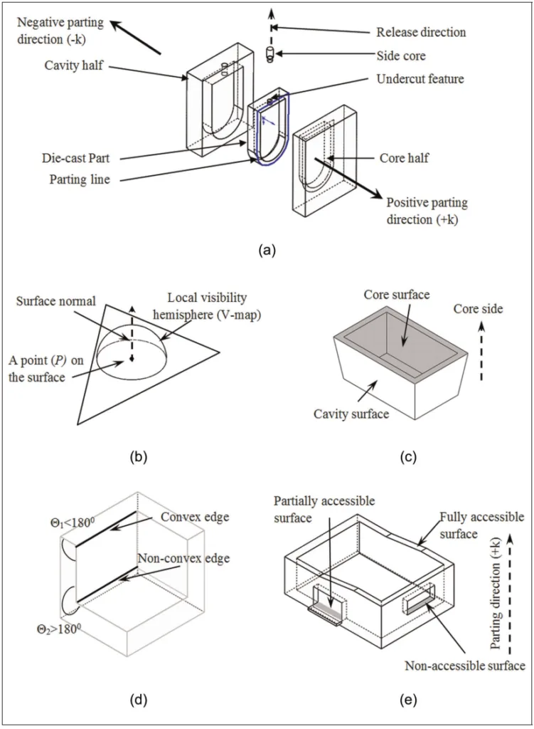
ダイカストは、溶融金属を永久金型(ダイとも呼ばれる)に圧力下で射出する製造プロセスです。ダイは一般的に、可動なコア(core)半型と固定されたキャビティ(cavity)半型の2つの部分で構成されます。金属の凝固後、コア半型が離れ、固体のダイカスト部品がダイから取り出されます。ダイカストプロセスで得られた製品は、二次加工がほとんどまたは全く不要で、すぐに使用できます¹。いくつかの重要なダイカスト用語を以下に簡単に説明し、Figure 1に図示します。
- Parting direction: ダイのコア半型とキャビティ半型が離れる方向。コアの移動方向は正のparting direction(+k)とされ、反対方向(-k)は負のparting direction(Figure 1(a))と呼ばれます²。
- Parting line: ダイのコア半型とキャビティ半型の接合部に対応するダイカスト製品上の継ぎ目または線(Figure 1(a))²。
- Feature: 何らかの際立った属性または側面。本稿の文脈では、featureは部品の識別可能な領域です。Featureは、設計feature、検査feature、機械加工feature、またはダイカストfeatureなど、ドメイン固有のものです。
- Undercut feature: 正のparting directionからも負のparting directionからもアクセスできないダイカスト部品の幾何学的領域(Figure 1(a))³。
- Side-core: undercut featureを成形するために使用される特殊な工具(Figure 1(a))²。
- Side-core release direction: side-coreがダイから離れる際の移動方向(Figure 1(a))²。
- Local visibility: 表面上の点における法線は、その点が局所的に見える方向を示します。同じ点は、半球であるそのvisibility map(V-map)からも局所的に見えます(Figure 1(b))⁴,⁵。
- Core/Cavity surfaces: それぞれダイのコア/キャビティ半型によって成形されるダイカスト部品の表面(Figure 1(c))²。
- Convex/Non-convex edges: 隣接する面がなす角度(材料側から測定)がそれぞれ180°未満/180°超であるエッジ(Figure 1(d))²。
ダイ設計には、リードタイムとダイカスト部品の製造コストに影響を与えるいくつかの活動が含まれ、多くの時間を要することが報告されています⁶。重要な活動の1つであるundercut featuresの識別は、parting lineの決定とコア-キャビティ設計に影響を与えます。さらに、undercut featuresを成形するための特殊な工具であるside-coreは、undercut featuresが識別された後に設計されます。通常、undercut featuresの識別は、ダイ設計の専門家がコンピュータ支援設計(CAD)ソフトウェアを使用して手動で行います。したがって、undercut feature recognitionは、ダイカストプロセスの設計-製造統合におけるギャップであると言えます。本研究は、このギャップを埋めるための取り組みであり、複雑なundercut featuresの自動識別と、それらをside-core設計を容易にするために単純なundercut featuresに分割する方法論を提案します。
4. 研究の概要:
研究トピックの背景:
ダイカスト金型の設計は、undercut featuresの識別が重要なステップとなる複雑なプロセスです。これらの形状は特殊な工具(side-cores)を必要とし、parting lineの配置やコア/キャビティ形状のような基本的な設計決定に影響を与えます。この識別プロセスを自動化することは、ダイカストにおける効率と統合を改善するために不可欠です。
先行研究の状況:
CADモデルからのfeature identification、特にダイカストおよび金型設計に関する先行研究では、visibility maps、spherical maps、グラフベース手法、block factor、grid line/column insertion test、3D ray detection、freedom cones、non-directional blocking graphs、グラフィックスハードウェアアクセラレーション、polyhedron face adjacency graph、幾何学的/位相的解析など、様々な技術が用いられてきました。研究者(例:Dhaliwal et al.⁷, Surti and Reddy⁸, Liu and Ramani⁹, Chen¹⁰, Hui and Tan¹¹, Wong et al.¹², Fu et al.¹³, Lu and Lee¹⁴, Yin et al.¹⁵, Ye et al.¹⁶,¹⁷, Khardekar et al.¹⁸, Banerjee and Gupta¹⁹, Kumar et al.²⁰, Madan et al.²¹, Fu²², Madan et al.²³, Huang²⁴, Bidkar and McAdams²⁵, Bassi et al.²⁶, Kumar et al.³, Ran and Fu²⁷)は、アンダーカットの検出、release directionsの決定、parting lines/surfacesの生成、金型形状の認識に焦点を当ててきました。しかし、文献レビュー(Table 1に一部要約)は、重要な研究ギャップが存在することを示しています。
研究の目的:
本研究は、複雑なundercut featuresに関する先行研究で特定されたギャップに対処することを目的としています。具体的な目的は以下の通りです:
- ダイカスト部品の複雑なundercut featuresを識別する。
- 複雑なundercut featuresを分類する。
- 識別された複雑なundercut featuresを単純なfeaturesに分割する。
- 単純なundercut featuresのrelease directionを決定する。
中核研究:
本研究の中核は、B-repモデルで表現されたダイカスト部品における複雑なundercut featuresの自動識別、分類、分割、およびrelease direction決定のためのシステムの開発と実装です。まず、visibilityとaccessibilityの概念を利用してundercut surfacesを識別します。次に、ルールベースアルゴリズムがこれらのfeaturesを分類します。複雑なアンダーカット(具体的には、unbounded、他のアンダーカットと交差するもの、および成形可能領域と交差するもの、平面サーフェスを仮定)をより単純なfeaturesに分割する方法論が提案されます。最後に、システムは各単純なundercut featureに対する適切なrelease directionを決定し、共通の方向を共有するものをグループ化して、後続のside-core設計を容易にします。
5. 研究方法論
研究設計:
本研究は、ダイカスト部品の境界表現(B-rep)モデルの幾何学的および位相的解析に基づくアルゴリズム的アプローチを採用しています。方法論は、以下の構造化された順序に従います:
- Parting directionに対する局所的なvisibilityに基づく表面分類。
- 接続されたNon-Convex Surfaces (NCSs)およびNon-Convex Edges (NCEs)によって形成されるNon-Convex Regions (NCRs)の識別。
- Singh and Madan [2]から適用されたアルゴリズムを用いた、parting directionにおける表面のaccessibility(fully accessible, non-accessible, partially accessible)の決定。
- Figure 5に詳述されたアルゴリズムを用いた、undercut surfaces(non-accessible patchesおよび特定のタイプのpartially accessible patches)の識別。
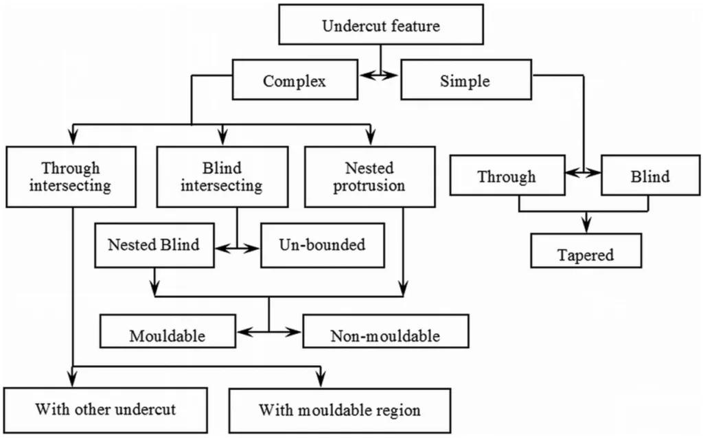
- 幾何学的特性(Figure 6, Figure 7)に基づいて、識別されたundercut featuresを単純および複雑なタイプ(例:blind depression, through depression, unbounded, nested)に分類。
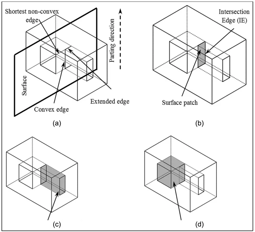
- 表面パッチ作成技術(Figure 8, Figure 9, Figure 10)を用いた、平面を持つ特定の複雑なundercut features(unbounded, intersecting)の単純なfeaturesへの分割。
- 候補となるrelease directionsに対するaccessibilityをチェックすることによる、各単純なundercut featureのrelease directionの決定(Figure 11, Figure 12)。
- 共通のrelease directionを共有する単純なundercut featuresのグループ化。
データ収集と分析方法:
入力データは、ダイカスト部品のB-repファイルとユーザー指定の正のparting direction(+k)で構成されます。幾何学的分析は主に以下に依存します:
- 内積 (Dot Product, DP): 表面法線(ni)とparting direction(k)(DP = ni · k)に基づいて表面(up, down, neutral)を分類し、候補となるrelease direction(RDi)におけるaccessibility(DP = ni · RDi)を確認するために使用されます。
- Accessibility Algorithm: 同じNCR内の他の表面による障害物をチェックして、表面がparting directionにおいてfully accessible、non-accessible、またはpartially accessibleであるかを決定するアルゴリズム(Singh and Madan [2]に基づく)。
- 幾何学的形状認識: NCEs, NCSs, NCRs, convex edge loops, および表面間の共通エッジの識別。
- 表面パッチ作成: 複雑なfeaturesを分割するために、エッジの延長またはループ境界に基づいて新しい表面(パッチ)を生成します(Figure 8, 9, 10参照)。
- ルールベース分類: エッジループタイプ(convex, NCE)および交差に基づいてルールを適用し、undercut featuresを分類します(Figure 6, Figure 7)。
この方法論は、ケーススタディのダイカスト部品(Figure 13, Figure 14)を用いて実装および検証されました。
研究トピックと範囲:
本研究は、side-core設計を支援することを目的とした、ダイカスト部品における複雑な undercut featuresの自動識別、分類、分割、およびrelease direction決定に特に焦点を当てています。範囲は以下の仮定と制限によって定義されます:
- ダイカスト部品は成形可能であると仮定します。
- 主たるparting direction(+k)は入力として提供されます。
- 複雑なundercut featuresを分割する方法論は、主に平面サーフェスのみを含むfeaturesに対して開発および実証されます。
- 本研究は、特定のタイプの複雑なfeatures(unbounded、他のundercut featuresと交差するもの、および成形可能領域と交差するもの)を扱います。
6. 主要な結果:
主要な結果:
本研究は、以下の能力を持つシステムを成功裏に開発し、実証しました:
- 自動識別: Parting directionに対するaccessibility analysisを用いて、B-repモデルから複雑なundercut featuresを識別。
- 分類: 定義された類型論(Figure 6)に基づいて識別されたundercut featuresを分類し、単純タイプと様々な複雑タイプ(例:unbounded, intersecting, nested - Figure 7)を区別。
- 分割: 幾何学的操作(表面パッチ作成など)を用いて、複雑なundercut features(平面を持つunbounded, intersecting)を複数の単純なundercut featuresに分割(Figures 8, 9, 10)。結果として得られる各単純なfeatureは、固有の抜き勾配方向を持ちます。
- Release Direction決定: 表面のaccessibilityに基づいて候補方向を評価することにより、各単純なundercut featureに対する適切なrelease direction (RD)を決定(Figures 11, 12)。
- グループ化: 共通のrelease directionを共有する単純なundercut featuresをグループ化し、共通のside-coresを設計するための重要な情報を提供。
例となる部品(Figure 13, Figure 14)への実装は、複雑なfeatureの識別から、割り当てられたrelease directions(RD1, RD2など)を持つ単純なfeaturesへの分割までのプロセスを示し、方法論を検証しました。このシステムは、手動の方法と比較して大幅な時間短縮を提供します(報告によると1~2分対30~40分)。結果は、ダイ設計の自動化を促進し、設計-製造統合を強化します。特定の平面ジオメトリで実証されましたが、基礎となるアルゴリズムは汎用的であり、わずかな変更で他の形状にも適用可能であると考えられます。
図リスト:
- Figure 1. ダイカスト金型用語の図解表現:(a) 代表的なダイカスト金型の分解図、(b) 表面の局所的可視性、(c) コアおよびキャビティ表面、(d) エッジの分類、(e) 表面の分類。
- Figure 2. ダイカスト部品の表面分類。
- Figure 3. 非凸領域の概略図:(a) 非凸エッジ(NCE)および非凸表面(NCS)、(b) 非凸領域。
- Figure 4. 部分的にアクセス可能な表面の成形可能性。(a) アクセス不可能なパッチの境界内部にあるアクセス可能なパッチ、(b) アクセス不可能なパッチの境界外部にあるアクセス可能な表面パッチ、(c) 表面パッチの成形可能性の決定。
- Figure 5. undercut features識別のための情報フロー図。
- Figure 6. ダイカストundercut featuresの分類ツリー。
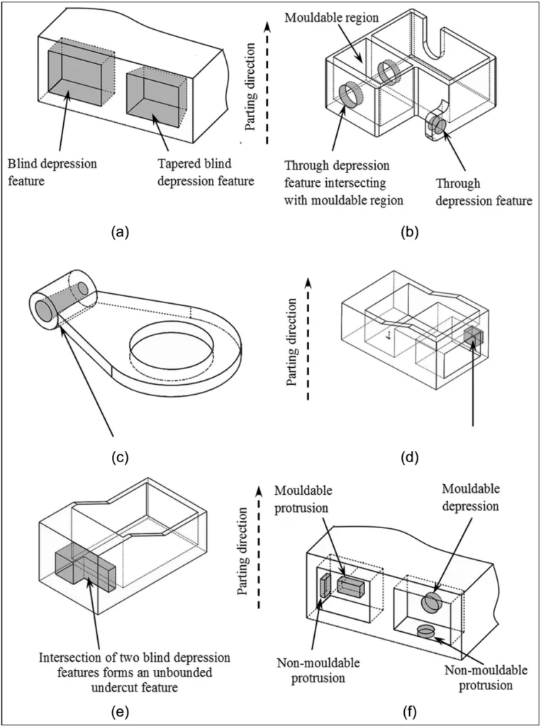
- Figure 7. undercut featuresの例:(a) 袋状undercut features、(b) 貫通undercut features、(c) テーパー付き貫通凹部形状、(d) undercut領域と交差する貫通凹部形状、(e) 非有界undercut feature、(f) ネストされた凹部および凸部形状。
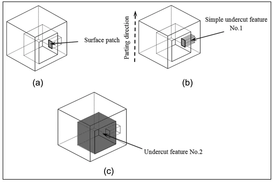
- Figure 8. 非有界undercut featureの分割:(a) 最短の非凸エッジの延長、(b) 表面パッチの作成、(c) 単純undercut feature No. 1、(d) 単純undercut feature No. 2。
- Figure 9. 複雑な交差undercut featureの分割:(a) 凸エッジループで囲まれた表面パッチの作成、(b) 複雑undercut feature分割の例、(c) 別のundercut featureと交差するundercut featureの分割。
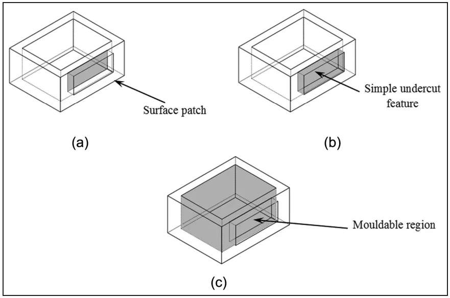
- Figure 10. undercut featureと成形可能領域の交差部分の分割:(a) 凸エッジループで囲まれた表面パッチの作成、(b) 成形可能領域と交差する単純undercut featureの識別、(c) undercut featureと交差する成形可能領域の識別。
- Figure 11. 単純undercut featureのrelease direction決定のための情報フロー図。RD: release direction; DP: 内積。
- Figure 12. release directionの決定。
- Figure 13. 例題部品No. 1の結果:(a) 複雑undercut featuresを持つ部品モデル、(b) 複雑undercut featuresの分割、(c) release directionを持つside-core。RD: release direction。
- Figure 14. 例題部品No. 2の結果:(a) 複雑undercut featuresを持つ部品モデル、(b) 複雑undercut featuresの分割、(c) release directionを持つside-cores。RD: release direction。
7. 結論:
ダイカスト部品のside-core設計のための複雑なundercut featuresの自動認識システムが開発されました。このシステムは、主たるparting directionに対して単一の抜き方向を持たないfeaturesに対応します。これは、複雑なundercut featuresを識別、分類し、そして決定的に複数の単純なundercut featuresに分離する新しい方法を提供します。結果として得られる各単純なfeatureには、固有の抜き(release)方向が割り当てられます。さらに、システムは共通の抜き方向を共有する単純なfeaturesをグループ化し、これは効率的な共通side-coresを設計するための不可欠な入力となります。
提案されたシステムは、平面サーフェスを持つ複雑なundercut featuresを示すダイカスト部品に実装およびテストされ、その結果は業界の慣行と比較して検証されました。特定のジオメトリで実証されましたが、中核となるアルゴリズムは汎用的であり、他の形状にもわずかな変更で適用可能です。重要な利点は、これらのタスクに必要な時間が手動の専門家による方法と比較して劇的に短縮されることです(1~2分対30~40分)。このシステムは、リードタイムを短縮し、コア、キャビティ、side-core設計などの後工程活動のための重要な情報を生成し、最終的にダイカスト産業におけるより良い設計-製造統合に貢献することにより、ダイ設計プロセスの自動化を促進します。
8. 参考文献:
- [1] Kalpakjian S and Schmid SR. Manufacturing engineering and technology. 4th ed. New Delhi: Pearson Education, 2011.
- [2] Singh R and Madan J. Systematic approach for automated determination of parting line for die-cast parts. Robot Cim: Int Manuf 2013; 29: 346–366.
- [3] Kumar V, Madan J and Gupta P. A system for design of multicavity die casting dies from part product model. Int J Adv Manuf Tech 2013; 67: 2083–2107.
- [4] Gan GH, Woo TC and Tang K. Spherical maps: their construction, properties and approximation. J Mech Des: T ASME 1994; 116: 357–363.
- [5] Elber G and Cohen E. Arbitrarily precise computation of Gauss maps and visibility sets for freeform surface. In: Proceedings of the third ACM symposium on solid modeling and applications (SMA ‘95), Salt Lake City, UT, 17–19 May 1995, pp.271–279. New York: ACM.
- [6] Fuh JYH, Wu SH and Lee KS. Development of a semi-automated die casting die design system. Proc IMechE, Part B: J Engineering Manufacture 2002; 216: 1575–1588.
- [7] Dhaliwal S, Gupta SK, Huang J, et al. Algorithms for computing global accessibility cones. J Comput Inf Sci Eng 2003; 3(3): 200–209.
- [8] Surti A and Reddy NV. Non-discretized approach to visibility analysis for automatic mold feature recognition using step part model. J Adv Manuf Syst 2012; 12(1): 1–16.
- [9] Liu M and Ramani K. Computing an exact spherical visibility map for meshed polyhedral. In: Proceedings of the 2007 ACM symposium on solid and physical modelling, Beijing, China, 4–6 June 2007, pp.367–372. New York: ACM.
- [10] Chen YH. Determination of parting direction based on minimum bonding box and fuzzy logic. Int J Mach Tool Manu 1997; 37(9): 1189–1199.
- [11] Hui KC and Tan ST. Mould design with sweep operations – a heuristic search approach. Comput Aided Design 1992; 24(2): 81–92.
- [12] Wong T, Tan ST and Sze WS. Parting line formation by slicing a 3D CAD model. Eng Comput 1998; 14: 330–343.
- [13] Fu MW, Fuh JYH and Nee AYC. Generation of optimal parting direction based on undercut features in injection moulded parts. IIE Trans 1999; 31: 947–955.
- [14] Lu HY and Lee WB. Detection of interference elements and release directions in die-cast and injection-moulded components. Proc IMechE, Part B: J Engineering Manufacture 2000; 214(6): 431–441.
- [15] Yin Z, Ding H and Xiong Y. Virtual prototyping of mould design: geometric mouldability analysis for near net shape manufactured parts by feature recognition and geometric reasoning. Comput Aided Design 2001; 33: 137–157.
- [16] Ye XG, Fuh JYH and Lee KS. A hybrid method for recognition of undercut features from moulded parts. Comput Aided Design 2001; 33: 1023–1034.
- [17] Ye XG, Fuh JYH and Lee KS. Automatic undercut feature recognition for side core design of injection molds. J Mech Design 2004; 126(3): 519–526.
- [18] Khardekar R, Burton G and McMains S. Finding feasible mold parting directions using graphics hardware. Comput Aided Design 2006; 38: 327–341.
- [19] Banerjee AG and Gupta SK. Geometrical algorithms for automated design of side actions in injection moulding of complex parts. Comput Aided Design 2007; 39: 882–897.
- [20] Kumar N, Ranjan R and Tiwari MK. Recognition of undercut features and parting surface of moulded parts using polyhedron face adjacency graph. Int J Adv Manuf Tech 2007; 34(1–2): 47–55.
- [21] Madan J, Rao PVM and Kundra TK. Die-casting feature recognition for automated parting direction and parting line determination. J Comput Inf Sci Eng 2007; 7(3): 236–248.
- [22] Fu MW. The application of surface demoldability and moldability to side-core designing die and mold CAD. Comput Aided Design 2008; 40: 567–575.
- [23] Madan J, Singh A and Kumar S. Recognition of intersecting features and identification of separable regions for design-manufacturing integration. In: Proceedings of the international conference on digital factory (ICDF), Trichy, India, 11–13 August 2008, pp.60–67.
- [24] Huang TS. Algorithms for recognizing undercut feature. J Technol 2008; 23(1): 61–69.
- [25] Bidkar RA and McAdams DA. Methods for automated manufacturability analysis of injection-molded and die-cast parts. Res Eng Des 2010; 21: 1–24.
- [26] Bassi R, Reddy NV and Bedi S. Automatic recognition of intersecting features for side-core design in two piece permanent molds. Int J Adv Manuf Tech 2010; 50: 421–439.
- [27] Ran JQ and Fu MW. Design of internal pins in injection mold CAD via the automatic recognition of undercut features. Comput Aided Design 2010; 42(7): 582–597.
- [28] Sunil VB and Pande SS. Automatic recognition of features from freeform surface CAD models. Comput Aided Design 2008; 40: 502–517.
- [29] Tan ST, Yuen MF, Sze WS, et al. Parting lines and parting surfaces of injection moulded parts. Proc IMechE, Part B: J Engineering Manufacture 1990; 204: 211–221.
9. 著作権:
- This material is a paper by "Ranjit Singh, Jatinder Madan and Rajesh Kumar". Based on "Automated identification of complex undercut features for side-core design for die-casting parts".
- Source of the paper: https://doi.org/10.1177/0954405413514744
本資料は上記の論文に基づいて要約されており、商業目的での無断使用は禁じられています。
Copyright © 2025 CASTMAN. All rights reserved.