本稿は、「[3D Printing and Additive Manufacturing]」誌に掲載された論文「[Parameter Optimization and Precision Control of Water-Soluble Support Cores for Hollow Composite Castings Fabricated by Slurry Microextrusion Direct Forming Method]」に基づいています。
1. 概要:
- 論文名: Parameter Optimization and Precision Control of Water-Soluble Support Cores for Hollow Composite Castings Fabricated by Slurry Microextrusion Direct Forming Method
- 著者: Jiefei Huang, Fuchu Liu, Yingpeng Mu, Chi Zhang, Xin Liu, Guangchao Han, and Zitian Fan
- 発行年: 2023
- 掲載学術誌/学会: 3D Printing and Additive Manufacturing
- キーワード: hollow composite castings, slurry microextrusion direct forming method, magnesium sulfate support core, parameter optimization, precision control
2. アブストラクト:
スラリーの含有量と成形プロセスパラメータの最適化は、スラリーマイクロ押出直接成形法において重要な効果をもたらします。本稿では、硫酸マグネシウム一水和物(MgSO4)とポリビニルピロリドン(PVP)を原料としてスラリーを調製し、スラリーの成分比と成形プロセスの最適化について議論しました。最適なスラリー含有量は、硫酸マグネシウム一水和物64 wt.%とPVP-EtOHからなるバインダー36 wt.%です。プリンティング速度、押出圧力、および押出径に対するプリンティング層高さの比率を含むプロセスパラメータが影響因子として選択されました。直交実験の結果、プリンティング速度850 mm/min、押出圧力250 kPa、押出径に対する層高さ510 μmが最適化されたプロセスパラメータであることが示されました。最適化されたプリンティングパラメータ下では、調製されたサンプルの表面粗さは23.764 μmであり、X、Y、Z方向の寸法偏差はそれぞれ0.71%、0.77%、2.56%でした。
3. 緒言:
航空宇宙、自動車、電気通信産業の急速な発展に伴い、複雑な内部空洞を持つ中空複合鋳造品がますます広く使用されるようになり、その構造は複雑化と精密化の方向に進んでいます。これらの鋳造品は複雑な内部オーバーハング中空構造を有しており、成形プロセス中に支持を提供し、鋳造後に除去される可溶性コアを必要とします。その結果、可溶性サポートコアの材料組成精度に対する要求が高まっています。
水溶性塩コアは、その良好な機械的強度と水溶性により注目を集めており、鋳造後のサポートコア除去率が高い複雑な中空複合鋳造品の製造に適しています。しかし、従来のサポートコア作製法には、複雑な金型設計、高エネルギーコスト、長いサイクルタイムといった欠点があり、複雑な構造の内部中空複合鋳造品の開発を著しく制約しています。したがって、金型なしで新しい水溶性塩サポートコア成形プロセスを探求することは非常に重要です。
近年、3Dプリンティングとも呼ばれる積層造形技術は、そのユニークな成形上の利点から注目を集めています。スラリーマイクロ押出直接成形法は、金型に頼らずに部品を自由に成形できる積層造形技術の一種です。低コスト、小型装置、高速成形、短いイタレーション期間という利点から、水溶性塩サポートコアの作製において幅広い応用が期待されています。
4. 研究の概要:
研究トピックの背景:
航空宇宙、自動車、電気通信産業における中空複合鋳造品の需要増加に伴い、複雑な内部構造を形成するための効率的で精密なサポートコア技術が求められています。水溶性塩コアは有望な解決策ですが、従来の製造方法には限界があります。スラリーマイクロ押出直接成形法は、この課題に対応できる新しいアプローチを提供します。
従来の研究状況:
従来の研究では、KNO3ベースやアルカリ金属炭酸塩・塩化物ベースの塩コアが溶融鋳造法などで作製されてきました。これらの方法は一定の成果を上げていますが、金型設計の複雑さやコスト面での課題がありました。スラリーベースの積層造形に関する研究も行われていますが、特にMgSO4とPVPを用いた水溶性コアの精密制御を目的としたスラリー組成とプロセスパラメータの系統的な最適化は十分に行われていませんでした。本論文では、「magnesium sulfate monohydrate (MgSO4) and polyvinylpyrrolidone (PVP) as raw materials」を用いたアルコールベースのDIW技術におけるパラメータ最適化と精度制御に関する報告は少ないと指摘しています。
研究の目的:
本研究の主な目的は、「slurry microextrusion direct forming methodを用いて、良好な表面品質を持つ水溶性塩サポートコアを製造するための最適化されたスラリー組成比と成形プロセスパラメータを提案すること」でした。固体含有量とバインダー含有量が水溶性塩サポートコアグリーン体の成形性に及ぼす影響を調査し、単一因子実験と直交実験によってプロセスパラメータをさらに調査・最適化し、高精度でより優れたコアを作製することを目指しました。
研究の核心:
本研究は、硫酸マグネシウム一水和物(MgSO4)とポリビニルピロリドン(PVP)を原料とし、スラリーマイクロ押出直接成形法を用いて水溶性サポートコアを作製する際の、スラリー含有量と成形プロセスパラメータの最適化に焦点を当てています。
- スラリー組成の最適化: MgSO4·H2Oを基材、PVP-K60を無水エタノールに溶解させたもの(PVP-EtOH)をバインダー兼可塑剤として使用しました。固体含有量(MgSO4·H2O)とバインダー(PVP-EtOH)濃度がスラリーの粘度と自己支持特性に及ぼす影響を調査しました。最適なスラリー組成は、MgSO4·H2O 64 wt.%、バインダー(エタノール中PVP-K60 25 wt.%)36 wt.%と決定されました。
- プロセスパラメータの最適化: 単一因子実験を実施し、プリンティング速度、押出圧力、層高さが、プリンティング精度(寸法偏差)とサンプルの表面粗さに及ぼす影響を調査しました。
- 直交実験: 単一因子実験の結果に基づき、プリンティングパラメータ(プリンティング速度、押出圧力、層高さ)を組み合わせ、それらの値を精密化することで、より高いプリンティング品質と精度を達成するために直交実験を設計・実施しました。回帰分析も行われました。
5. 研究方法論
研究デザイン:
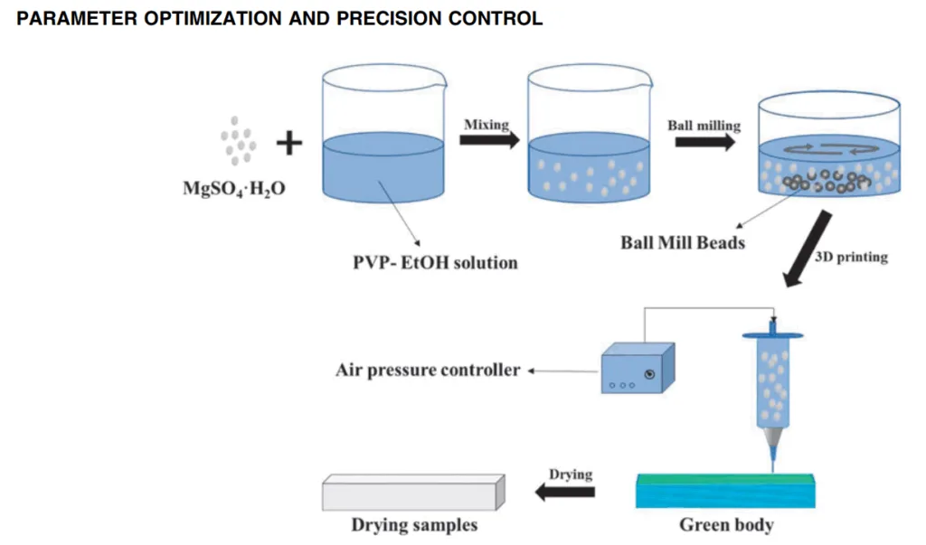
本研究では、MgSO4·H2Oを固体粉末、PVP-EtOH溶液をバインダーとしてスラリーを調製しました。
- スラリー調製: PVP-K60を無水エタノールに溶解させました。MgSO4·H2O粉末を添加し、手動で撹拌した後、9時間ボールミル処理を行い、安定した硫酸マグネシウムスラリーを得ました。
- スラリー特性評価: 固体含有量(MgSO4·H2O 61 wt.%~64 wt.%)とバインダー含有量(エタノール中のPVP)がスラリー粘度と自己支持特性(相対沈降高さ、プリンティング特性)に及ぼす影響を調査しました。
- プリンティングプロセス: 機械的動作モジュール、駆動インク押出装置、ソフトウェア制御システムを備えた自作のプリンティング装置を使用しました。内径600 μmのニードルを使用しました。プリンティングされたサンプルは60°Cで12時間乾燥させました。
- パラメータ最適化:
- 単一因子実験: プリンティング速度(600-1200 mm/min)、押出圧力(200-500 kPa)、層高さ(420-600 μm)が寸法偏差と表面粗さに及ぼす個々の影響を調査しました。
- 直交実験: L9直交表を用い、3つの因子(プリンティング速度: 750, 800, 850 mm/min; 押出圧力: 250, 300, 350 kPa; 層高さ: 450, 480, 510 μm)をそれぞれ3水準で設定し、寸法偏差と表面粗さを最小化する最適な組み合わせを見つけました。直交実験の結果について回帰分析を行いました。
データ収集と分析方法:
- 粘度測定: デジタル粘度計(NDJ-8S; Bonsey Instrument Shanghai Technology Co., Ltd., China)を使用しました。
- 表面粗さとプロファイル: 接触式粗さ計(JB-6C roughness profiler)を使用しました。
- 微細構造と形態: 超深度視野顕微鏡を用いてサンプルの表面形態を観察しました。
- 寸法偏差: S = (L2 - L1) / L1 の式を用いて計算しました。ここで、Sはプリントサイズ偏差率、L2は実際のプリンティングサイズ、L1は設計サイズです。
- 自己支持特性: 様々な固体含有量のスラリーの相対沈降高さと、異なる固体含有量のサンプルのプリンティング特性を観察することで評価しました。
- 統計分析: 直交実験の結果に対して極差分析と回帰分析を適用しました。
研究トピックと範囲:
- スラリー組成の最適化: 良好なレオロジー特性と成形性のためのMgSO4·H2O固体含有量とPVP-EtOHバインダー含有量の最適比率の決定。
- 成形プロセスパラメータの最適化:
- プリンティング速度がサンプル品質(寸法偏差、表面粗さ、形態)に及ぼす影響。
- 押出圧力がサンプル品質に及ぼす影響。
- 層高さがサンプル品質に及ぼす影響。
- 精密制御: 最適化されたスラリーとプロセスパラメータを通じて、作製されたサポートコアの寸法精度向上と表面粗さ低減。
- 研究範囲は、スラリーマイクロ押出直接成形法により作製されたMgSO4ベースの水溶性サポートコアに限定されました。
6. 主要な結果:
主要な結果:
- 最適スラリー組成: 最適なスラリー含有量は、硫酸マグネシウム一水和物64 wt.%と、PVP-EtOH(バインダー溶液中のPVP含有量25 wt.%)からなるバインダー36 wt.%であることが見出されました。この組成は、押出中の安定した構造を維持するための十分な強度と、優れた自己支持特性を提供しました。
- 単一因子実験の知見:
- プリンティング速度: 800 mm/minが最適であり、Z軸方向の寸法偏差と表面粗さが最も低くなりました。
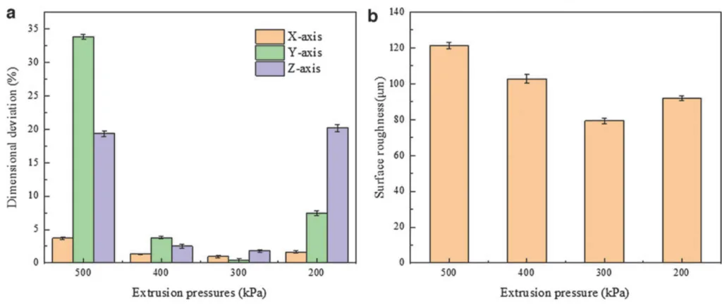
- 押出圧力: 300 kPaが最適であり、3方向すべての寸法偏差が最も低く、表面粗さも最も低くなりました。
- 層高さ: 480 μmが最適であり、寸法偏差と表面粗さが最も低くなりました。
- 直交実験による最適化:
- プリンティング品質に影響を与える最も重要な因子が特定されました。X軸、Y軸、Z軸の寸法偏差率および表面粗さに対する影響の大きさの順序は、概して押出圧力(B)> プリンティング速度(A)> 層高さ(C)でした。
- 最適化されたプリンティングプロセスパラメータは、プリンティング速度850 mm/min、押出圧力250 kPa、層高さ510 μm(全体的な最良性能、特にX軸偏差と表面粗さに対する回帰分析からのA1B3C1の組み合わせ。ただし、Y軸およびZ軸偏差については個別に他の組み合わせが最適でした)と決定されました。
- 最終的に達成された精度: 最適化されたプリンティングパラメータ(速度850 mm/min、圧力250 kPa、層高さ510 μm)下で作製されたサンプルは、以下を示しました:
- 表面粗さ: 23.764 μm。
- 寸法偏差: 0.71% (X軸), 0.77% (Y軸), 2.56% (Z軸)。
- プロセスパラメータと寸法偏差/表面粗さの関係を記述するために、以下の回帰式が開発されました:
- δχ = -6.79 – 0.001A + 0.012B + 0.009C (2)
- δy = 13.589 – 0.064A – 0.235B – 0.047C (3)
- δz = -9.267 – 0.032A + 0.213B – 0.027C (4)
- Ra = 56.267 – 0.102A + 0.373B – 0.042C (5)
図のリスト:
- FIG. 1. Flow chart of slurry preparation.
- FIG. 2. Partial slurry printing characteristics with different solid contents: (a) 54 wt.%, (b) 56 wt.%, (c) 58 wt.%, (d) 60 wt.%.
- FIG. 3. Viscosity of slurries at different solid loading and binder contents.
- FIG. 4. Relative settling heights of slurries with different solid contents.
- FIG. 5. Effect of solid contents on the self-supporting properties of the slurry: (a) 61 wt.%, (b) 62 wt.%, (c) 63 wt.%, (d) 64 wt.%.
- FIG. 6. Schematic representation of the effect of solid content on stack forming.
- FIG. 7. Sample photos at different printing speeds: (a) 1200 mm/min, (b) 1000 mm/min, (c) 800 mm/min, (d) 600 mm/min.
- FIG. 8. Surface profile of the samples at different printing speeds: (a) 1200 mm/min, (b) 1000 mm/min, (c) 800 mm/min, (d) 600 mm/min.
- FIG. 9. Microscopic morphology of the samples at different printing speeds: (a) 1200 mm/min, (b) 1000 mm/min, (c) 800 mm/min, (d) 600 mm/min.
- FIG. 10. Effect of different printing speeds on the quality of the formed samples: (a) dimensional deviation rate, (b) surface roughness.
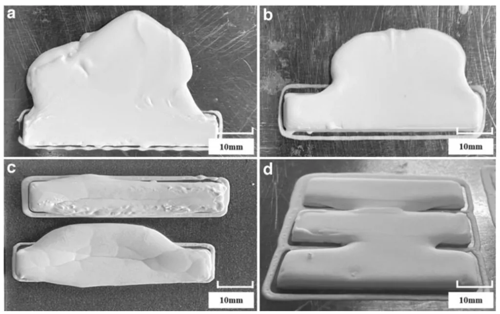
- FIG. 11. Sample photos at different extrusion pressures: (a) 500 kPa, (b) 400 kPa, (c) 300 kPa, (d) 200 kPa.
- FIG. 12. Surface profile of the samples at different extrusion pressures: (a) 500 kPa, (b) 400 kPa, (c) 300 kPa, (d) 200 kPa.
- FIG. 13. Microscopic morphology of the samples at different extrusion pressures: (a) 500 kPa, (b) 400 kPa, (c) 300 kPa, (d) 200 kPa.
- FIG. 14. Effect of different extrusion pressures on the forming quality of the samples: (a) dimensional deviation rate, (b) surface roughness.
- FIG. 15. Effect of different layer heights on printed samples.
- FIG. 16. Samples at different layer heights: (a) 600 μm, (b) 540 μm, (c) 480 μm, (d) 420 μm.
- FIG. 17. Surface profile of the samples at different layer heights: (a) 600 μm, (b) 540 μm, (c) 480 μm, (d) 420 μm.
- FIG. 18. Microscopic morphology of the samples at different layer height: (a) 600 μm, (b) 540 μm, (c) 480 μm, (d) 420 μm.
- FIG. 19. Effect of different layer heights on the forming quality of the samples: (a) dimensional deviation rate, (b) surface roughness.
- FIG. 20. Sample printing after process optimization: (a) sample view, (b) microscopic view of surface laminations, (c) 3D pseudo-color view of surface, (d) surface roughness view.
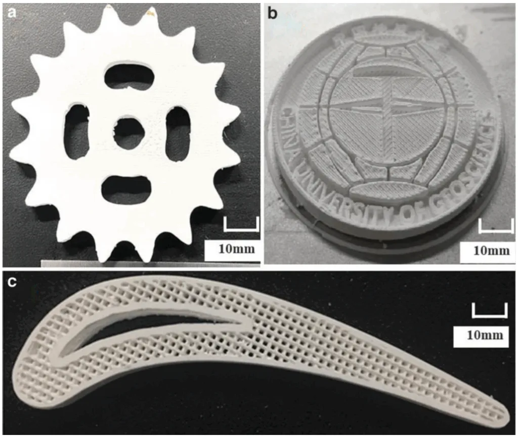
- FIG. 21. Different samples prepared by the optimized printing parameter obtained by the orthogonal experimental method: (a) Gear shape, (b) CUG badge, (c) Porous structure.
7. 結論:
本稿では、水溶性無機塩スラリーを用いたアルコールベースのDIW法により、中空複合鋳造品の成形に適したサンプルを作製する新しい方法を提案しました。スラリーは、MgSO4·H2Oを骨材、無水エタノール中のPVPをバインダーおよび溶媒として調製されました。本研究では、スラリーの配合とマイクロ押出直接成形プロセスパラメータの最適化を行いました。
主な結果は以下の通りです。
(1) スラリーの固体含有量64 wt.%、バインダー中のPVP含有量25 wt.%(総バインダー溶液36 wt.%)は、押出中の安定した構造と優れた自己支持特性を維持するのに十分な強度を有します。
(2) 単一因子実験の結果、プリンティング速度が速く、押出圧力が低く、層高さが高いほど、アンダーロード成形欠陥が生じやすく、逆に、プリンティング速度が遅く、押出圧力が高く、層高さが低いほど、オーバーロード成形欠陥が生じやすいことが示されました。
(3) 直交実験と分析により、プリンティングプロセスパラメータの主な影響順序は、押出圧力、プリンティング速度、層高さであることが確認されました。最適化されたパラメータ(プリンティング速度850 mm/min、押出圧力250 kPa、層高さ510 μm)を用いることで、良好な成形精度と表面品質を持つサンプルが得られました。寸法偏差はそれぞれ0.71% (X)、0.77% (Y)、2.56% (Z)であり、表面粗さは23.764 μmでした。
最適化されたプロセスは、硫酸マグネシウムベースの水溶性サポート塩コアを用いた高品質なプリンティング部品の製造に有効です。
8. 参考文献:
- [1. Dong X, Yang H, Zhu X, et al. High strength and ductility aluminium alloy processed by high pressure die casting. J Alloys Compounds 2019;773:86–96.]
- [2. Liu F, Jiang P, Huang Y, et al. A water-soluble magnesium sulfate bonded sand core material for manufacturing hollow composite castings. Comp Struct 2018;201:553–560.]
- [3. Liu F, Fan Z, Liu X, et al. Aqueous gel casting of water-soluble calcia-based ceramic core for investment casting using epoxy resin as a binder. Int J Adv Manufact Technol 2016;86(5–8):1235–1242.]
- [4. Xiao Z, Harper LT, Kennedy AR, et al. A water-soluble core material for manufacturing hollow composite sections. Comp Struct 2017;182:380–390.]
- [5. Liu F, Tu S, Gong X, et al. Comparative study on performance and microstructure of composite water-soluble salt core material for manufacturing hollow zinc alloy castings. Mater Chem Phys 2020;252:123257.]
- [6. Gong X, Jiang W, Liu F, et al. Effects of glass fiber size and content on microstructures and properties of KNO3-based water-soluble salt core for high pressure die casting. Int J Metalcast 2021;15(2):520–529.]
- [7. Tu S, Liu F, Li G, et al. Fabrication and characterization of high-strength water-soluble composite salt core for zinc alloy die castings. Int J Adv Manufact Technol 2018;95(1–4):505–512.]
- [8. Yaokawa J, Miura D, Anzai K, et al. Strength of salt core composed of alkali carbonate and alkali chloride mixtures made by casting technique. Mater Transact 2007;48(5):1034–1041.]
- [9. Qu P, Xiong D, Zhu Z, et al. Inkjet printing additively manufactured multilayer SOFCs using high quality ceramic inks for performance enhancement. Addit Manufact 2021;48:102394.]
- [10. Wei X, Pan Y, Chen Z. 3D printing of NiZn ferrite architectures with high magnetic performance for efficient magnetic separation. J Eur Ceram Soc 2022;42(4):1522–1529.]
- [11. Liu Z, Miao K, Lian W, et al. Effect of mould baffle technology on stray grain formation in single crystal blades by integral fabrication based on 3D printing. China Foundry 2021;18(5):433–441.]
- [12. Miao K, Zhou H, Gao Y, et al. Laser powder-bed-fusion of Si3N4 reinforced AlSi10Mg composites: Processing, mechanical properties and strengthening mechanisms. Mater Sci Eng A 2021;825:141874.]
- [13. Hirt L, Reiser A, Spolenak R, et al. Additive manufacturing of metal structures at the micrometer scale. Adv Mater 2017;29(17):1604211.]
- [14. Li Z, Li H, Yin J, et al. A review of spatter in laser powder bed fusion additive manufacturing: In situ detection, generation, effects, and countermeasures. Micromachines (Basel) 2022;13(8):1366.]
- [15. Chen Q, Jing Y, Yin J, et al. High reflectivity and thermal conductivity Ag-Cu multi-material structures fabricated via laser powder bed fusion: Formation mechanisms, interfacial characteristics, and molten pool behavior. Micromachines (Basel) 2023;14(2):362.]
- [16. Yin J, Zhang W, Ke L, et al. Vaporization of alloying elements and explosion behavior during laser powder bed fusion of Cu–10Zn alloy. Int J Machine Tools Manufact 2021;161:103686.]
- [17. Webbe Kerekes T, Lim H, Joe W Y, et al. Characterization of process-deformation/damage property relationship of fused deposition modeling (FDM) 3D-printed specimens. Addit Manufact 2019;25:532–544.]
- [18. Romero-Ocaña I, Molina SI. Cork photocurable resin composite for stereolithography (SLA): Influence of cork particle size on mechanical and thermal properties. Addit Manufact 2022;51:102586.]
- [19. Beloshenko V, Chishko V, Plavan V, et al. Production of filter material from polypropylene/copolyamide blend by material extrusion-based additive manufacturing: Role of production conditions and ZrO2 nanoparticles. 3D Print Addit Manufact 2021;8(4):253–262.]
- [20. Gao G, Du Z, Zhang W, et al. Investigation and improvement of pushing dislocation in ceramsite sand three-dimensional printing. 3D Print Addit Manufact 2023;10(2):289–297.]
- [21. Shi Y, Zhang J, Wen S, et al. Additive manufacturing and foundry innovation. China Foundry 2021;18(4):286–295.]
- [22. Tang S, Yang L, Fan Z, et al. A review of additive manufacturing technology and its application to foundry in China. China Foundry 2021;18(4):249–264.]
- [23. Tian X, Wu L, Gu D, et al. Roadmap for additive manufacturing: Toward intellectualization and industrialization. Chin J Mech Eng 2022;1(1):100014.]
- [24. Hao L, Tang D, Sun T, et al. Direct ink writing of mineral materials: A review. Int J Precis Eng Manufact Green Technol 2021;2:8.]
- [25. Fang Y, Guo Y, Liu T, et al. Advances in 3D bioprinting. Chin J Mech Eng 2022;1(1):100011.]
- [26. Chu X, Tang X, Chen W, et al. Direct-ink-write printing performance of zeolite catalysts with porous structures. Ceram Int 2023;49(9):13531–13541.]
- [27. Roth CC, Tancogne-Dejean T, Mohr D. Plasticity and fracture of cast and SLM AlSi10Mg: High-throughput testing and modeling. Addit Manufact 2021;43:101998.]
- [28. Jang S, Boddorff A, Jang DJ, et al. Effect of material extrusion process parameters on filament geometry and inter-filament voids in as-fabricated high solids loaded polymer composites. Additive Manufact 2021;47:102313.]
- [29. Plocher J, Panesar A. Review on design and structural optimisation in additive manufacturing: Towards next-generation lightweight structures. Mater Design 2019;183:108164.]
- [30. Truby RL, Lewis JA. Printing soft matter in three dimensions. Nature 2016;540(7633):371–378.]
- [31. Wang R, Zhu P, Yang W, et al. Direct-writing of 3D periodic TiO2 bio-ceramic scaffolds with a sol-gel ink for in vitro cell growth. Mater Design 2018;144:304–309.]
- [32. Peng E, Zhang D, Ding J. Ceramic robocasting: Recent achievements, potential, and future developments. Adv Mater 2018;30(47):e1802404.]
- [33. Tang S, Yang L, Li G, et al. 3D printing of highly-loaded slurries via layered extrusion forming: Parameters optimization and control. Addit Manufact 2019;28:546–553.]
- [34. Li G, Tang S, Yang L, et al. Fabrication of soluble salt-based support for suspended ceramic structure by layered extrusion forming method. Mater Design 2019;183:108173.]
- [35. Gong X, Liu X, Chen Z, et al. 3D printing of high-strength water-soluble salt cores via material extrusion. Int J Adv Manufact Technol 2022;118(9–10):2993–3003.]
- [36. Duoss EB, Twardowski M, Lewis JA. Sol-gel inks for direct-write assembly of functional oxides. Adv Mater (Weinheim) 2007;19(21):3485–3489.]
- [37. Lewis JA. Direct-write assembly of ceramics from colloidal inks. Curr Opin Solid State Mater Sci 2002;6(3):245–250.]
- [38. Smay JE, Cesarano J, Lewis JA. Colloidal inks for directed assembly of 3-D periodic structures. Langmuir 2002;18(14):5429–5437.]
- [39. Sun Y, Peng C, Wang X, et al. Rheological behavior of Al2O3 suspensions containing polyelectrolyte complexes for direct ink writing. Powder Technol 2017;320:223–229.]
- [40. Xia Y, Lu Z, Cao J, et al. Microstructure and mechanical property of Cf/SiC core/shell composite fabricated by direct ink writing. Script Mater 2019;165:84–88.]
9. 著作権:
- 本資料は、「Jiefei Huang, Fuchu Liu, Yingpeng Mu, Chi Zhang, Xin Liu, Guangchao Han, and Zitian Fan」による論文です。「Parameter Optimization and Precision Control of Water-Soluble Support Cores for Hollow Composite Castings Fabricated by Slurry Microextrusion Direct Forming Method」に基づいています。
- 論文の出典: [https://doi.org/10.1089/3dp.2023.0136]
本資料は上記の論文に基づいて要約したものであり、商業目的での無断使用を禁じます。
Copyright © 2025 CASTMAN. All rights reserved.