本稿は、「クイーンズランド大学」より発行された論文「Mechanisms of Leaker Formation in Aluminium High Pressure Die Casting」に基づいています。

1. 概要:
- 論文名: Mechanisms of Leaker Formation in Aluminium High Pressure Die Casting (アルミニウム高圧ダイカストにおけるリーカー欠陥の形成メカニズム)
- 著者: Stephen Thompson
- 発行年: 1998年
- 発行学術誌/学会: University of Queensland (Thesis for Masters of Engineering Science by Research)
- キーワード: 論文中に明記なし
2. 抄録:
本報告書では、一般的および特定のアルミニウム高圧ダイカストにおけるリーカー形成メカニズムの理解を深めます。この理解はいくつかの段階を経て展開されます。
既発表の研究のレビューにより、高圧ダイカストにおけるリーカー形成に寄与する可能性のある鋳造欠陥を特定します。さらに、これらの各欠陥とそれらが鋳物の耐圧性に与える影響を理解するために、文献のレビューに焦点を当てます。レビューされた欠陥は、コールドフレーク、コールドシャット、ドラッグマーク、ガス気孔、酸化膜、介在物、表面層を除去または損傷させる二次作業、収縮気孔、焼付き、および表面割れです。この情報は、特定の鋳物におけるリーカーの「根本原因」の特定を支援する「フォールトツリー」を形成するために編集されます。
次に、自動車用ウォーターインレット鋳物の観察を用いて、特定の例におけるリーカーの可能性のある根本原因を特定します。リーカーの根本原因となる可能性のある欠陥として、コールドシャット、ガス気孔、収縮気孔、揮発性流体による表面気孔、ドラッグマーク、および表面割れが見つかりました。鋳物の重要領域の機械加工も、リーカー形成の可能性を高めるように見えました。
これらの欠陥の中で、コールドシャットがリーカーの最も重要な根本原因であるように見えました。コールドシャットおよびリーカーの発生に対するプロセスパラメータの影響を分析するために、金型および溶湯温度を操作してリーカーの発生を増加させる構造化された試験が実施されました。結果は、コールドシャットの発生および程度とリーカーの発生との間に強い関連性があることを示しています。さらに、結果は金型温度とリーカーの発生との間の関連性を示しています。
最後に、自動車用ウォーターインレット鋳物におけるリーカーの発生を低減するための多くの戦略が提案され、可能性のあるさらなる調査についての提案がなされています。
3. はじめに:
本文書は、Stephen Thompson氏の1998年の修士論文「アルミニウム高圧ダイカストにおけるリーカー欠陥の形成メカニズム」で提示された主要な調査結果と方法論を要約したものです。原著は、自動車用ウォーターインレット鋳物を特定のケーススタディとして、アルミニウム高圧ダイカストで「リーカー」欠陥が発生する理由について包括的な調査を提供しています。この要約は、ダイカスト技術の業界専門家および研究者向けに、ハンドブックスタイルの形式で、中核となる概念、研究の進展、および結論を提示することを目的としています。
4. 研究の要約:
研究トピックの背景:
高圧ダイカストは、鋳物あたりのコストが低く、生産率が高いため、複雑な部品の一般的な製造プロセスです。薄肉で寸法精度の高い部品を製造できます。しかし、特に流体を収容または送液することを目的とした鋳物は、「リーカー」と呼ばれる、圧力下で流体が鋳物壁を通過することを可能にする欠陥に悩まされる可能性があります。このような欠陥は、不良品となるか、封孔剤による含浸処理が必要になります。本研究は、リーカー欠陥が発生しやすいアルミニウム合金CA313製の自動車用ウォーターインレット鋳物に焦点を当てています。リーカーの形成は、多くの場合、他の鋳造欠陥の組み合わせの結果です。
先行研究の状況:
本論文の第2章では、高圧ダイカストにおけるリーカー形成に寄与する可能性のある鋳造欠陥を特定するために、既発表の文献をレビューしています。文献によると、リークが発生するためには、鋳物の表面層と中心部を貫通する経路が存在しなければなりません。潜在的な原因として特定された欠陥は次のとおりです。
- Cold Flakes (コールドフレーク)
- Cold Shuts (コールドシャット)
- Drag Marks (ドラッグマーク)
- Gas Porosity (ガス気孔)
- Oxide Films (酸化膜)
- Particulate Inclusions (介在物)
- Secondary Operations that Remove or Damage the Surface Layer (表面層を除去または損傷させる二次作業)
- Shrinkage Porosity (収縮気孔)
- Soldering (焼付き)
- Surface Cracks (表面割れ)
レビューでは、この情報を「フォールトツリー」(Figure 2.18)にまとめ、リーカーの根本原因を特定するのに役立てています。各潜在的な原因について、文献では次の点が調査されました。
- リーカーを引き起こす可能性のある条件。
- その形成を支配するメカニズム。
- その発生を低減するための戦略。
本論文では、ガス気孔のような一部の欠陥は、リーカーの主な原因としてはしばしば軽視されるものの(分離した気泡を形成する傾向があるため)、他の欠陥との相互作用や特定の形成メカニズム(例:揮発性の離型剤によるもの)がリーク経路を引き起こす可能性があると指摘しています。収縮気孔、特に凝固範囲の長い亜共晶合金におけるデンドライト間気孔は、特に表面層が損なわれた場合にリーク経路を形成する可能性のある一般的な特徴として特定されています。
研究の目的:
本研究は以下の目的を持っていました(6ページに記載):
I. リーカー形成の一般的なメカニズムを特定するために、既存の発表された研究をまとめる。
II. ウォーターインレット鋳物のプロセスと鋳物の観察を用いて、リーカー形成の可能性のあるメカニズムを特定する。
III. 発表された文献に基づいて、ウォーターインレット鋳物のリーカー形成に重要な影響を与える可能性のあるパラメータを提案する。
IV. ステップIIで特定されたメカニズムとステップIIIで提案された重要なパラメータの重要性を、制御された実験を用いて確認する。
V. 発表された知識と収集された経験を用いて、ウォーターインレット鋳物におけるリーカーの発生を低減するために使用できる可能性のある戦略を提案する。
中核研究:
研究の中核はいくつかの段階で構成されていました。
- 文献レビュー(第2章): 既存の研究からリーカーの潜在的な原因とその形成メカニズムを特定し、フォールトツリーを作成。
- 観察研究(第3章): 自動車用ウォーターインレット鋳物を検査し、一般的なリーカー発生箇所と関連する欠陥を特定。これには、リークが発生した鋳物と健全な鋳物の目視検査および断面観察が含まれた。コールドシャット、露出したガス/収縮気孔(特に機械加工後)、揮発性流体による表面気孔、ドラッグマーク、微小な亀裂などの欠陥が観察された。コールドシャットとリーカーの間には強い相関関係が認められた。
- 実験的調査(第4章): 特定のプロセスパラメータ(金型温度と溶湯温度)がウォーターインレット鋳物におけるコールドシャットとリーカーの発生に与える影響を分析するために、構造化された試験を実施。金型冷却レベル(オイルと非冷却キャビティを使用)と溶湯温度を体系的に変更。ショットエンドパラメータ、金型温度、リーカー発生率に関するデータを収集し分析。
- 予測関係の構築: カイ二乗検定や線形/重回帰分析などの統計的手法を用いて、制御変数(オイル冷却レベル、設定溶湯温度)、測定変数(金型キャビティ温度、プランジャー変位)、および鋳造結果(リーカー発生)の間の関係を確立。
- 戦略の提案(第5章): 調査結果に基づいて、特定のウォーターインレット鋳物におけるリーカー発生を低減するための戦略が提案され、将来の研究のための提案も行われた。
5. 研究方法論
研究デザイン:
研究は多段階アプローチで設計されました。
- 文献レビュー: 高圧ダイカストにおけるリーカー形成に関連する鋳造欠陥に関する既発表の研究の包括的なレビュー。
- 観察研究: 特定の工業用鋳物(自動車用ウォーターインレット)の詳細な検査により、一般的なリーカー発生箇所と関連する欠陥を特定。これには、リークが発生した鋳物と健全な鋳物の両方の分析が含まれた。
- 制御実験: 主要なプロセスパラメータ(金型温度と溶湯温度)がリーカー形成に与える影響を調査するために、構造化された試験を設計。これらのパラメータを操作し、鋳造品質への影響を観察。実験では2キャビティ金型を使用し、異なる冷却条件を同時に適用できるようにした。
- 統計分析: 実験から収集されたデータを統計的手法を用いて分析し、相関関係を特定し、リーカー発生の予測モデルを開発。
データ収集と分析方法:
データ収集:
- 文献: 学術論文、会議議事録、業界報告書から入手。
- 鋳物検査(第3章): リークが発生したウォーターインレット鋳物と健全なウォーターインレット鋳物の目視検査。内部欠陥と微細構造を調査するために、断面観察と顕微鏡検査を使用。コールドシャットは0から4のスケールで定量化。
- プロセスパラメータ(第4章試験):
- Machine Shot End Parameters (機械ショットエンドパラメータ): プランジャー変位と油圧システム圧力用のトランスデューサーを使用して測定。パラメータには、サイクルタイム、異なる段階でのプランジャー速度と変位、油圧、遅延時間が含まれた (Table 4.1)。
- Die Cavity Temperatures (金型キャビティ温度): 金型開放直後に、各キャビティの4つの代表的な場所で携帯型表面プローブを使用して測定 (Figure 4.3)。すべてのショットについて温度を内挿。
- Molten Metal Temperature (溶湯温度): 10ショットごとに測定し、各鋳物について内挿。
- Leaker Testing (リーカー試験): 鋳物を水に浸し、300 Kpaの圧力で試験し、気泡の発生を観察。これは合否判定試験であった (Appendix A.4)。
- Alloy Composition (合金組成): 試験中に採取したサンプルについて分析 (Appendix A.1, Appendix F.2)。
分析方法:
- Fault Tree Analysis (フォールトツリー分析): 文献からリーカーの潜在的な原因を要約するために使用 (Figure 2.18)。
- Correlation Analysis (相関分析) (第3章): コールドシャットのレベルとリーカーの発生との間の相関の有意性を確認するために、χ² (カイ二乗) 検定を使用 (Table 3.1, Appendix E)。
- Statistical Analysis of Trial Data (試験データの統計分析) (第4章):
- χ² (カイ二乗) 検定: オイル冷却レベルと溶湯温度がリーカー確率に与える影響の有意性を判断するために使用 (Tables 4.5, 4.7)。
- Linear Regression (線形回帰): 鋳造結果 (リーカー発生、y) と制御入力変数 (オイル冷却レベル x1、設定溶湯温度 x2) の間の関係を適合させるために使用 (Equations 4.2, 4.3, 4.4)。
- Coefficient of Determination (R²) (決定係数): 測定された入力パラメータ (例:金型温度、ショットエンドパラメータ) との回帰によって説明されるリーカー発生の変動の割合を評価するために使用 (Equation 4.5, Table 4.10)。
- Multiple Linear Regression (重回帰分析): 測定された入力パラメータの組み合わせ (例:4つのキャビティ内温度と射出終了時のプランジャー変位) に基づいてリーカー発生を予測するために使用 (Figure 4.9, Figure 4.10)。
- t-test (t検定): 溶湯温度が平均金型温度に与える影響の有意性を評価するために使用 (Equation 4.6, 4.7)。
研究トピックと範囲:
- 主要研究トピック: アルミニウム高圧ダイカストにおけるリーカー欠陥の形成メカニズム。
- 特定の焦点: CA313アルミニウム合金製の自動車用ウォーターインレット鋳物。
- 調査された主要欠陥: コールドシャット、ガス気孔、収縮気孔、およびそれらとプロセスパラメータとの関係。
- 調査されたプロセスパラメータ:
- 金型温度(オイル冷却チャネルを介して制御)。
- 溶湯温度。
- その他のショットエンドパラメータ(プランジャー速度、変位、圧力)。
- 範囲: 研究には、文献レビュー、工業用鋳物の観察分析、および工業用ダイカスト機での制御実験が含まれた。調査結果は主に調査された特定の鋳物に適用可能であるが、リーカー形成の一般原則に関する洞察を提供する。この研究では、測定可能なプロセスパラメータに基づいてリーカー発生を予測する可能性も調査した。
6. 主な結果:
主な結果:
- 文献の編集: HPDCにおけるリーカーの原因となる可能性のある欠陥の包括的なリストが編集された。これには、コールドフレーク、コールドシャット、ドラッグマーク、ガス気孔、酸化膜、介在物、二次作業の影響、収縮気孔、焼付き、表面割れが含まれる。リーカーをその根本原因まで追跡するためのフォールトツリー(Figure 2.18)が開発された。
- ウォーターインレット鋳物の観察結果(第3章):
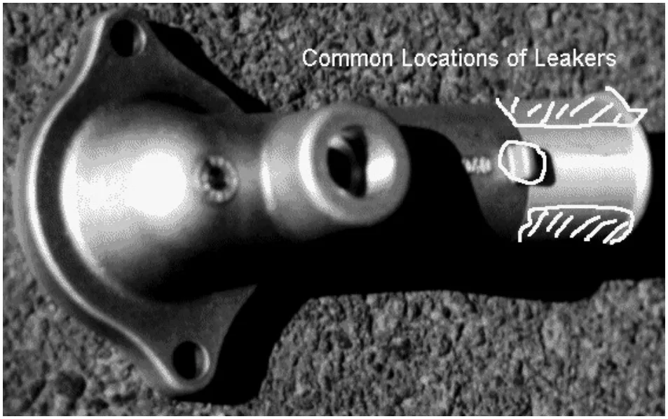
- リーカーは主にチューブの機械加工された端部またはその近くで発生し、しばしばパーティングラインの近くで見られた。一部のリーカーはラグの基部近くで見られた。
- 機械加工は内部気孔を露出させる重要な要因として特定された。
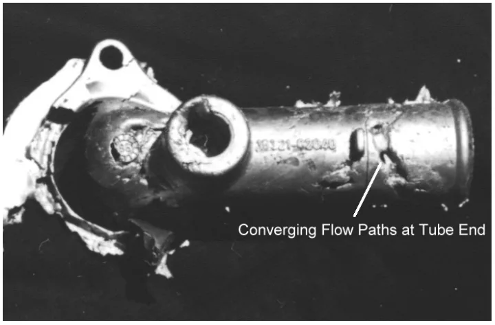
- チューブ内面のコールドシャットはリーカーの発生と強く相関していた(Table 3.1)。これらのコールドシャットは、内面から多孔質の鋳物中心部への経路を提供する。
- 機械加工された表面の露出したガス/収縮気孔は一般的であったが、リーカーとの直接的な関連性はコールドシャットほど明確ではなかった。ガス混入は、早期のショット切り替えと分岐するランナー設計に起因するとされた(Figures 3.9, 3.10, 3.11)。
- シリンダー内面の表面気孔(揮発性の離型剤によるものと思われる)は、リーカーとともに観察されることがあり、通常はコールドシャットと同時に発生していた。
- ラグ周辺の微小な亀裂(凝固応力やその他の欠陥に関連)は、時折リーカーと関連していた。
- 実験結果(第4章):
- 金型/溶湯温度の影響: 金型温度(オイル冷却レベルによって制御)はリーカー形成に大きな影響を与えた。金型冷却が高い(金型温度が低い)ほど、リーカーの発生確率が高くなった(Table 4.4, Table 4.5)。溶湯温度が低いほどリーカーが多くなる傾向が見られたが、この試験内では統計的に有意ではなかった(Table 4.6, Table 4.7)。
- リーカー発生率の予測:
- オイル冷却レベルとリーカー発生率の間には非線形の関係が見られ、これは回帰分析を用いてモデル化できた(Equations 4.3, 4.4; Figures 4.4, 4.5)。
- 測定された金型キャビティ温度(ゲート、固定キャビティ、可動キャビティ、スライドコア)はリーカーの発生と相関を示し、決定係数(R²)は約0.04から約0.09の範囲であった(Table 4.10)。
- 4つのキャビティ内温度と射出終了時のプランジャー変位を用いた重回帰モデルは、リーカー発生率を合理的に予測した(Figures 4.9, 4.10)。
- 金型の熱的状態: この研究は、金型温度測定がリーカーの予測因子として使用できるほど、金型の熱的状態に関する十分な情報を提供することを示した。スライドコア温度はオイル冷却レベルに強く影響された(Figure 4.11)。平均金型温度は溶湯温度によって測定可能なほど影響された(Figure 4.12)。
- その他のパラメータ: 射出中の総プランジャー変位(注入された溶湯量を示す)も、リーカー形成と顕著な関係を示した。通常よりも長い変位(溶湯量が少ない)は、より多くのリーカーと相関していた。
図のリスト (Figure Name List):
![Figure 2.10 Short Shots in Zinc and Aluminium Alloys Showing How Gas
Entrapment Can Occur in the Cavity. Shots A, B, and C Differ in the Amount of
Metal Ladled. [12]](https://castman.co.kr/wp-content/uploads/image-2366.webp)


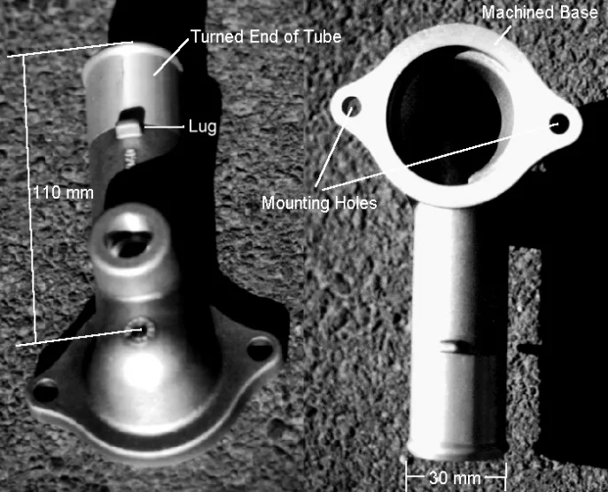
- Figure 1.1 Automotive Water Inlet Casting.
- Figure 1.2 Flow Chart of Part Manufacture.
- Figure 2.1 Fracture Along the Face of a Cold Flake.
- Figure 2.2 Mechanism of Cold Flake Formation.
- Figure 2.3 Heat Losses From Alloy During Casting Cycle.
- Figure 2.4 Flow Lines on Flat Plate Castings Showing Difference Between Casting Filled by Full Width of Fan Gate (a) and Casting Filled by Partially Blocked Gate (b).
- Figure 2.5 "Large Gate Pores … Exposed by Machining to Create a Leaker."
- Figure 2.6 Air Entrapment at too Low and too High a First Stage Velocity.
- Figure 2.7 Wave Formed at Critical First Stage Plunger Speed.
- Figure 2.8 Optimum Acceleration Profiles For Different Shot Fill Ratios.
- Figure 2.9 Air Entrapment in a Poorly Designed Runner.
- Figure 2.10 Short Shots Showing How Gas Entrapment Can Occur in the Cavity.
- Figure 2.11 Typical Inclusions in Die Cast Aluminium Alloys.
- Figure 2.12 Tendency for Sludge Formation as a Function of Temperature and Sludge Factor.
- Figure 2.13 Interdendritic Shrinkage in Sand Cast Gun Metal Casting.
- Figure 2.14 Solidification Shrinkage in Aluminium Silicon Alloys.
- Figure 2.15 Shrinkage Porosity Distributions at Different Alloy Compositions.
- Figure 2.16 Shrinkage Feeding Using Directional Solidification.
- Figure 2.17 Surface Cracking in a Zinc Casting.
- Figure 2.18 Fault Tree Summarising the Major Causes of Leakers.
- Figure 3.1 Photograph of Water Inlet Casting Showing Common Sites of Leakers.
- Figure 3.2 Likely Porosity Distribution at Tube End, Showing Effect of Overflows and Machining.
- Figure 3.3 Water Inlet Die Cavity Showing Location of Overflows.
- Figure 3.4 Short Shot Showing Last Areas to Fill.
- Figure 3.5 Restrained Sections Near Tube End.
- Figure 3.6 Cold Shut at Surface of Leaking Casting Leading to Porous Inner Region.
- Figure 3.7 Large Cold Shut Leaving Void Through Casting Centre.
- Figure 3.8 Extensive Gas Porosity Found Through Section of Tube End.
- Figure 3.9 Diverging Runner Section of Water Inlet Casting.
- Figure 3.10 Shot Timing for Water Inlet Casting.
- Figure 3.11 Short Shot Showing Flow Through Runner.
- Figure 3.12 Surface Porosity on Internal Face of Tube.
- Figure 3.13 Section Through Surface Porosity on Internal Face of Tube Leading to Interconnected Pores Within the Casting.
- Figure 3.14 Section Through Surface Porosity on Internal Face of Tube that Appears to be Isolated from Porosity Within the Casting.
- Figure 3.15 Drag Marks on Internal Wall of Tube.
- Figure 3.16 Small Crack Running Through Casting Near Base of Lug.
- Figure 3.17 Cracks Associated With Large Gas Pores Near Base of Lug.
- Figure 4.1 Diagram of Cooling Line Set-up During Trial.
- Figure 4.2 Summary of Experimental Design and Expected Effects.
- Figure 4.3 Locations of Temperature Measurements in Cavity.
- Figure 4.4 Plot of Predicted Leaker Rate, Using Equation 4.3, Versus Shot Number.
- Figure 4.5 Plot of Predicted Leaker Rate, Using Equation 4.4, Versus Shot Number.
- Figure 4.6 Plot of the Value of Linear Regression Based on Measured Metal Temperature Versus Trial Shot Number.
- Figure 4.7 Plot of the Value of Linear Regression Based on Sliding Core Temperature Versus Trial Shot Number
- Figure 4.8 Plot of the Value of Linear Regression Based on Moving Cavity Temperature Versus Trial Shot Number
- Figure 4.9 Prediction of Leakers Using Multiple Linear Regression.
- Figure 4.10 Average Values of Multiple Linear Regression.
- Figure 4.11 Relationship Between Casting Cavity Core Temperature and Oil Cooling Level.
- Figure 4.12 Effect of Metal Temperature on Average Die Temperature.
- Figure 5.1 Cross Section Through Tube Wall Showing Cold Shuts, Internal Porosity, and Material Removal Combining to Provide a Path for Leakage.
- Figure A.1 Full Shot Trace for Water Inlet Casting.
- Figure A.2 Close Ups of Cavity Filling Period of Three Shot Traces.
- Figure A.3 Water Inlet Casting With Runners and Overflows.
- Figure A.4 Area of Casting Obscured by Support During Pressure Testing.
- Figure B.1 Enlarged Shot Trace for Water Inlet Casting.
- Figure C.1 Optimum Shot Profile for Water Inlet Casting.
- Figure C.2 Actual Shot Profile for Water Inlet Casting.
- Figure D.1 Level 0 (No Cold Shuts)
- Figure D.2 Level 1 (Small Cold Shuts)
- Figure D.3 Level 2 (Moderate Cold Shuts)
- Figure D.4 Level 3 (Extensive Cold Shuts)
- Figure D.5 Level 4 (Severe Cold Shuts)
7. 結論:
本研究で提示された情報から、いくつかの重要な結論を導き出すことができます。
- リーカーの発生を分析する際、鋳物は表面領域と鋳物中心部に分けることができます。これらのすべてがリーカー発生のためのリーク経路を含んでいなければなりません。その後、リーク欠陥の診断と低減のための論理的な手順が存在します。
- 鋳造合金から金型への熱伝達率は、ウォーターインレット鋳物におけるコールドシャットの発生に決定的な影響を与えます。
- 鋳物表面のコールドシャットは、ウォーターインレット鋳物におけるリーカーの発生と強い関連性があります。
- 重要な鋳造入力の状態分析によって、主要な鋳造結果を予測する能力が実証されました。これは、高圧ダイカストプロセスの監視を通じて、そのような主要な鋳造結果の発生を生産において予測し制御できることを示しています。
8. 参考文献:
- [1] LaVelle, ‘Aluminium Die Casting and Factors Affecting Pressure Tightness’, Transactions of the American Foundrymen's Society, Volume 70, 1962.
- [2] Walkington, ‘Short Course on Analysis of Die Casting Defects’, Cooperative Research Centre for Alloy and Solidification Technology, 1995.
- [3] Holz, ‘Trouble-Shooting Aluminium Die Casting Quality Problems’, 7th International Die Casting Congress, 1972.
- [4] Murray, ‘Defects in Pressure Die Castings as Pertaining to Low Gas Pressure Applications’, CSIRO Consultation Report 90/M/101, Commonwealth Scientific and Industrial Research Organisation, 1990.
- [5] Harding, Bennet, and Robinson, ‘Production of Aluminium Die Castings Using a Fan Gate [3] Some Factors Affecting Conditions at the Orifice’, 8th SDCE International Die Casting Exposition and Congress, 1975.
- [6] Iwahori, Nakamura, Tozawa, and Yamamoto, ‘Metal Flowing Behavior in Die Castings and Defects in Aluminium Die Castings’, 13th SDCE International Die Casting Congress and Exposition, 1985.
- [7] Murray, Chadwick, and Ghomashchi, ‘Aluminium Alloy Solidification in High Pressure Die Castings’, Materials Australasia, June 1990.
- [8] Murray, ‘Shot Sleeves, a Quality Control’, Die Casting Bulletin, April 1996.
- [9] Herman, ‘Die Casting Technology - Calculations’, Die Casting Education Project RMIT University, 1995.
- [10] Davis and Robinson, ‘Production of Aluminium Die Castings Using a Fan Gate [2] The Effect of Casting Conditions at the Gate on Casting Quality’, 8th SDCE International Die Casting Exposition and Congress, 1975.
- [11] Editor of the Die Casting Engineer, ‘Eliminating Surface Defects on Zinc Die Castings’, Die Casting Engineer, January/February 1977.
- [12] Stuhrke and Wallace, ‘Gating of Die Castings’, Transactions of the American Foundrymen’s Society, Volume 73, 1966.
- [13] Neff, ‘Principles of Molten Metal Processing for Improving Die Cast Quality’, 16th NADCA Congress and Exposition, 1991.
- [14] Titone, ‘Important Considerations in the Trimming of Die Castings’, 5th SDCE National Die Casting Congress, 1968.
- [15] Johnson, Bishop, and Pellini, ‘Application of Chills to Improving Pressure Tightness of Gun Metal (88-8-4)’, Transactions of the American Foundrymen's Society, Volume 62, 1954.
- [16] Veinik, ‘Thermodynamic Factors in Metal Injection: Effect of Friction on Gas Content and Quality’, 4th SDCE National Die Casting Exposition and Congress, 1966.
- [17] Garber, ‘Theoretical Analysis and Experimental Observation of Air Entrapment during Cold Chamber Filling’, Die Casting Engineer, May/June 1982.
- [18] Thome and Brevick, ‘Optimal Slow Shot Velocity Profiles For Cold Chamber Die Casting’, 18th NADCA Congress, 1995.
- [19] Luis-Martin and Robla, ‘Evaluation of Gas Porosity in Zinc Die Castings’, 12th SDCE International Die Casting Congress and Exposition, 1983.
- [20] Miller, ‘Inclusion Control of Die Casting Alloys’, Die Casting Engineer, September/October 1984.
- [21] Shivkumar, Apelian, and Brucher, ‘Melt Cleanliness in Die Cast Aluminium Alloys’, 16th NADCA Congress and Exposition, 1991.
- [22] Anderson, ‘Shot Peening to Reduce Porosity in Die Castings’, Modern Metals, Volume 9 Number 1, 1953.
- [23] DePue and Pennington, ‘Influence of Silicon on Gun Metal Alloys’, Transactions of the American Foundrymen's Society, Volume 70, 1962.
- [24] Gordon, Meszaros, Naizer, and Mobley, ‘Equations for Predicting the Percent Porosity in Die Castings’, 17th NADCA Congress, 1993.
- [25] Garber and Draper, ‘Shrinkage in #380A Aluminium Alloy’, Die Casting Engineer, November/December 1979.
- [26] Otte, ‘Castability of Aluminium Alloy 380’, Report for the Cooperative Research Centre for Alloy and Solidification Technology, 1997.
- [27] Taylor, ‘The Role of Iron and Other Elements in the Formation of Porosity in Al-Si-Cu Alloy Castings’, Department of Mining, Minerals, and Materials Engineering, University of Queensland, 1997.
- [28] Kalghatgi, ‘Effect of Silicon Content on Porosity in Aluminium Die Castings with More than 1/4-in. Wall Thickness’, 14th SDCE International Die Casting Congress and Exposition, 1987.
- [29] Herman, ‘Die Casting Technology - Die Casting Process and Die Design Level II’, Die Casting Education Project RMIT University, 1997.
- [30] Kulunk, Shabestari, Gruzleski, and Zuliani, ‘Beneficial Effects of Strontium on A380 Alloy’, Transactions of the American Foundrymen's Society, 1996.
- [31] Sugiyama, Yonekura, and Ookouchi, ‘Transferred Pressure and Casting Qualities of Aluminium Diecasting’, Diecasting World, September 1996.
- [32] Arnberg, Dahle, Paradies, and Syvertsen, ‘Factors Affecting the Castability of Aluminium Foundry Alloys’, International Conference on Casting and Solidification of Light Alloys, August 1995.
- [33] Garber and Draper, ‘The Effects of Process Variables on the Internal Quality of Aluminium Die Castings’, 10th SDCE International Die Casting Exposition and Congress, 1979.
- [34] Micks and Zabek, ‘Identifying Some Common Problems With Aluminium Castings’, Transactions of the American Foundrymen’s Society, Volume 81, 1973.
- [35] Chu, Cheng, and Shivpuri, ‘Soldering Phenomenon in Aluminum Die Casting: Possible Causes and Cures’, 17th NADCA Congress, 1993.
- [36] ‘Engineering Design, (12.7 Fault Tree Analysis)’, Text, GET DETAILS FROM NICK
- [37] ASM International, ‘Metals Handbook - Volume 2, Properties and Selection: Nonferrous Alloys and Special-Purpose Materials’, 10th Edition, ASM International, 1990.
- [38] ASM International, ‘Metals Handbook - Volume 9, Metallography and Microstructure’, 9th Edition, ASM International, 1985.
- [39] Walpole and Myers, ‘Probability and Statistics for Engineers and Scientists’, Fifth Edition, Macmillan Publishing Company, 1993.
- [40] Ball and Buckwell, ‘Work out Statistics “A” Level’, Macmillan Education Ltd., 1986.
- [41] Moroney, ‘Facts from Figures’, Second Edition, Penguin Books Ltd., 1957.
- [A1] Buhler, ‘Operating Manual for Buhler H250B-P Horizontal Cold Chamber Die Casting Machine’, Buhler. (Referenced in Appendix A)
- [B1] Herman, ‘Die Casting Technology - Calculations’, Die Casting Education Project RMIT University, 1995. (Referenced in Appendix B)
- [B2] Iwahori, Nakamura, Tozawa, Yamamoto, ‘Metal Flowing Behavior in Die Castings and Defects in Aluminium Die Castings’, 13th SDCE International Die Casting Congress and Exposition, 1985. (Referenced in Appendix B)
- [B3] ASM International, ‘Metals Handbook - Volume 2, Properties and Selection: Nonferrous Alloys and Special-Purpose Materials, 10th Edition’, ASM International, 1990. (Referenced in Appendix B)
- [C1] ASM International, ‘Metals Handbook - Volume 2, Properties and Selection: Nonferrous Alloys and Special-Purpose Materials, 10th Edition’, ASM International, 1990. (Referenced in Appendix C)
- [C2] Herman, ‘Die Casting Technology - Calculations’, Die Casting Education Project RMIT University, 1995. (Referenced in Appendix C)
- [E1] Walpole and Myers, ‘Probability and Statistics for Engineers and Scientists’, Fifth Edition, Macmillan Publishing Company, 1993. (Referenced in Appendix E)
- [E2] Moroney, ‘Facts from Figures’, Second Edition, Penguin Books Ltd., 1957. (Referenced in Appendix E)
9. 著作権:
- 本資料は、「Stephen Thompson」氏の論文です。「Mechanisms of Leaker Formation in Aluminium High Pressure Die Casting」に基づいています。
- 論文の出典:10.13140/RG.2.2.25896.08963
本資料は上記論文に基づいて要約されており、商業目的での無断使用を禁じます。
Copyright © 2025 CASTMAN. All rights reserved.