この論文の紹介は、['Rheinisch-Westfälischen Technischen Hochschule Aachen'] によって発行された ['An Automatic CAE Tool for autonomous feasibility assessment of aluminum gravity die castings – development and calibration'] に基づいて作成されました。
1. 概要:
- タイトル: アルミニウム重力ダイカストの自律的な実現可能性評価のための自動CAEツール – 開発とキャリブレーション (An Automatic CAE Tool for autonomous feasibility assessment of aluminum gravity die castings – development and calibration)
- 著者: Marcus Schopen, M.Sc.
- 出版年: 2022年
- 発行ジャーナル/学会: Rheinisch-Westfälischen Technischen Hochschule Aachen
- キーワード: 提供された文書の抜粋には明示的にリストされていませんが、内容に基づくと、キーワードには以下が含まれます:自動CAEツール (Automatic CAE Tool)、実現可能性評価 (Feasibility Assessment)、アルミニウム重力ダイカスト (Aluminum Gravity Die Castings)、開発 (Development)、キャリブレーション (Calibration)、鋳造シミュレーション (Casting Simulation)、凝固 (Solidification)、気孔率 (Porosity)、SDAS、効率向上手法 (Efficiency-enhancing methods)。
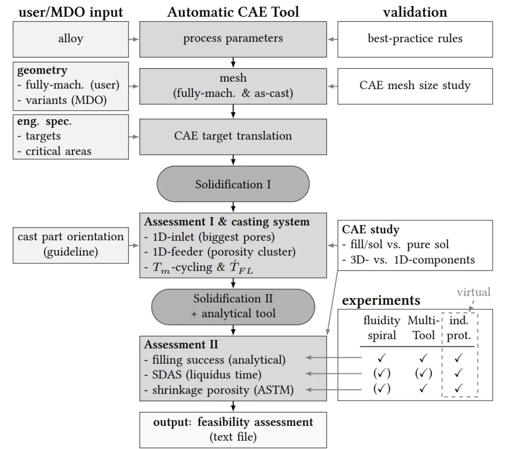
length-dependent cooling rate 𝑇̇𝐹𝐿, engineering specification (eng. spec.), industrial prototypes (ind.
prot.)
2. 抄録または序論
本論文では、次世代の開発プロセスにおける、学際的な設計最適化 (MDO) を可能にし、設計エンジニアが設計コンセプトの初期段階で鋳造部品の形状バリアントの実現可能性と品質を定量的かつ効率的に評価できるようにするために、完全に自動化された CAE ツールの必要性が高まっていることを述べています。主な研究課題は次のとおりです。
I) 最高の初期条件下で迅速かつ効率的な方法でシミュレーションをセットアップ、実行、評価し、定量的実現可能性評価のために鋳造専門家の手動によるユーザー介入を必要としない、完全に自動化された CAE ツールを開発することは可能か?
II) 開発された自動 CAE ツールとその効率向上手法をキャリブレーションおよび検証するために、どのレベルの試験データ品質が必要か – CAE 手法全体が同様の部品に新たな課題で転用可能になるほど正確かつ信頼性が高いか?
本研究では、主要な実現可能性効果であるため、「充填成功 (filling success)、微細構造の品質指標としての二次デンドライトアーム間隔 (SDAS)、および引け巣気孔率 (shrinkage porosity)」を調査対象の指標としています。開発された CAE ツールは、「鋳造欠陥の低減に関して可能な限り最高の初期鋳造プロセス条件(上限) 」を前提としており、「トポロジー最適化と製品設計の間の初期設計段階」での適用を目的として設計されています。解決策は「ベストプラクティスルール(上限)」に基づいており、「最終的なプロセス設計、例えば、フィーダーとインレットの数/位置に関する推奨事項」を提供することを目的としています。ツールのキャリブレーションと検証、およびその「感度とケース非依存性」の研究が重要です。
3. 研究背景:
研究トピックの背景:
鋳造部品の稼働性能は、「部品設計」だけでなく、「鋳型内の鋳造部品の向き、ゲートおよびフィーダー(サイズ、位置)、およびプロセスパラメータ(充填速度、注湯温度、鋳型温度)」などの製造効果にも左右されます。「鋳造プロセスの制約と要件は、属性要件(強度、耐久性、騒音振動ハーシュネス NVH、衝突)と同様に、設計最適化において等しく重要です。」従来の CAE アプローチは、「鋳造専門家のスキルと専門家主導の分析ループ」に依存しており、設計反復の回数が制限され、CAE の適用が製品開発の後期段階に限定されています。
既存研究の状況:
鋳造評価のための既存の CAE アプローチは、多くの場合、「手動のコンピュータ支援エンジニアリング (CAE) アプローチ」であり、専門家の介入が必要です。文献レビューでは、「充填成功、微細構造 (SDAS)、および引け巣気孔率」が主要な品質指標として重要であることが強調されています。先行研究では、シャーシ部品用合金、永久鋳型鋳造、品質指標、鋳造欠陥、および鋳造の最適化戦略が調査されています。しかし、設計初期段階での実現可能性評価のための完全自動化された CAE ツールが必要です。
研究の必要性:
「次世代の開発プロセスでは、学際的な設計最適化 (MDO) ツールだけでなく、設計エンジニアが設計コンセプトの初期段階で鋳造部品の形状バリアントの実現可能性と品質を定量的かつ効率的に評価できるようにするために、完全に自動化された CAE ツールとエキスパートシステムが必要です。」設計の初期段階で鋳造の実現可能性を効率的かつ自律的に評価し、手動による専門家の介入への依存を減らし、設計反復を迅速化できる「自動 CAE ツール」が明らかに必要です。
4. 研究目的と研究課題:
研究目的:
主な研究目的は、「アルミニウム重力ダイカストの自律的な実現可能性評価」のための「自動 CAE ツール」を開発および検証することです。このツールは、「最適化ループへの統合または鋳造専門家主導の手動 CAE アプローチのスタンドアロンツールとして、オープンインターフェースを備えた自動 CAE ツールを代替する」ことを目的としています。
主な研究:
主な研究は以下に焦点を当てています。
- 「シミュレーションを迅速かつ効率的な方法で、最高の初期条件下でセットアップ、実行、評価し、手動によるユーザー介入を必要としない自動 CAE ツール」の開発。
- ツールとその「効率向上手法」をキャリブレーションおよび検証し、正確性、信頼性、および類似部品への新たな課題への転用可能性を確保すること。
- 主要な指標として「充填成功、微細構造の品質指標としての二次デンドライトアーム間隔 (SDAS)、および引け巣気孔率」を調査すること。
研究仮説:
本論文では、従来の形式の研究仮説は明示的に述べられていません。ただし、暗黙の仮説は、研究課題と目的から推測できます。
- 完全自動化された CAE ツールは、アルミニウム重力ダイカストの自律的な実現可能性評価のために開発できると仮説を立てています。
- 効率向上手法は、方向性のある実現可能性評価の精度を損なうことなく、計算時間を大幅に短縮するために CAE ツールに実装できると仮説を立てています。
- 実験データは、自動 CAE ツールとその効率向上手法をキャリブレーションおよび検証するために使用できると仮説を立てています。
5. 研究方法
研究デザイン:
この研究では、開発と検証のアプローチを採用しています。「自動 CAE ツール」の開発、流動性スパイラル試験からの実験データを使用したキャリブレーション、マルチツール実験による検証、および産業用プロトタイプでの妥当性と感度の評価が含まれます。
データ収集方法:
実験データは、以下の鋳造実験から収集されました。
- 冷却と充填度を調査するための流動性スパイラル鋳型。
- 冷却、充填挙動、および気孔率を評価するためのマルチツールデモンストレーター。
- 鋳造中の温度曲線を測定するための熱電対 (TC)。
- 気孔率を分析するための X 線および CT スキャン。
- 微細構造と気孔率タイプを特性評価するための金属組織学および SEM。
- 気孔率定量化のためのアルキメデス密度測定およびブリスター試験。
分析方法:
この研究では、以下を組み合わせて利用しています。
- ベストプラクティスと設計ルールを確立するための文献レビュー。
- ツール開発と検証のための Inspire Cast® を使用した CAE シミュレーション。
- 充填成功評価のための分析手法。
- CAE ツールをキャリブレーションおよび検証し、実験データを分析するための統計分析 (相関行列、回帰分析)。
- 検証と妥当性評価のための実験結果とシミュレーション結果の定量的および定性的な比較。
研究対象と範囲:
研究は以下に焦点を当てています。
- アルミニウム重力ダイカスト、特に A356 合金を使用。
- 2 つのデモンストレーター形状: 流動性スパイラルとマルチツール。
- 適用と感度調査のための産業用プロトタイプシャーシ部品 (FLCA および RLCA)。
- 主要な品質指標: 充填成功、SDAS、および引け巣気孔率。
- プロセスパラメータ: 注湯温度、鋳型温度、および冷却条件。
6. 主な研究結果:
主な研究結果:
- アルミニウム重力ダイカストの自律的な実現可能性評価のための完全な「自動 CAE ツール」の開発。
- 「効率向上手法」の実装: 充填シミュレーションから純粋凝固および分析的充填成功評価への代替、および 3D コンポーネントの代わりに 1D コンポーネントの実装。
- 流動性スパイラル実験を使用した CAE ツールのキャリブレーションと、マルチツール実験を使用した検証。
- 実験による分析的充填基準と 1D フィーダーコンポーネントの検証。
- 産業用プロトタイプ (FLCA および RLCA) でのツールの感度と妥当性の実証。
- デフォルトの HTC データセットを使用することの限界と、異なる鋳造部品設計に対する HTC コンポーネントクラスの必要性の特定。
提示されたデータの分析:
論文では、広範なデータ分析を示しています。
- 実験とシミュレーション間の温度曲線の比較。キャリブレーション後、良好な一致を示す。
- 幾何学的流路長とスパイラル長の比較。ほぼ完全な一致を示す。
- 実験とシミュレーション間の充填度比較。 =0.3 で良好な一致を示す。
- CT スキャンによる気孔率推定の比較。不均一な HTC と Inspire Cast® における気孔率シミュレーションの限界により、気孔位置のずれを示す。
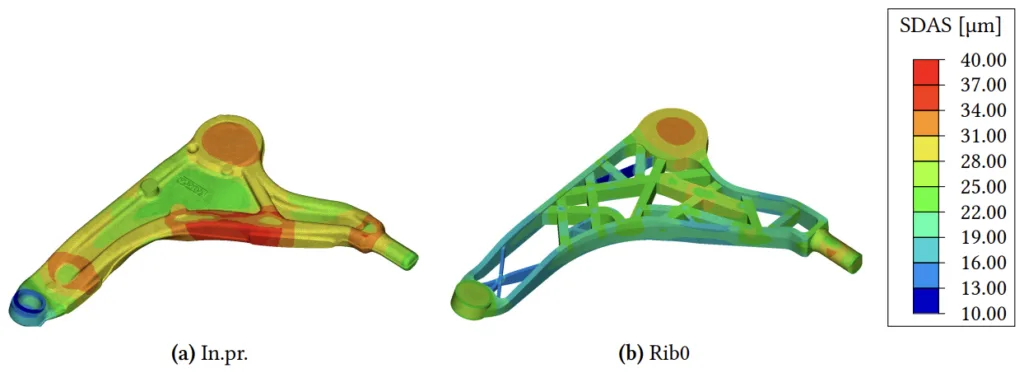
- FLCA 設計バリアントの感度調査。充填成功、SDAS、および気孔率の関連する違いを特定するツールの能力を実証する。
図の名前リスト:
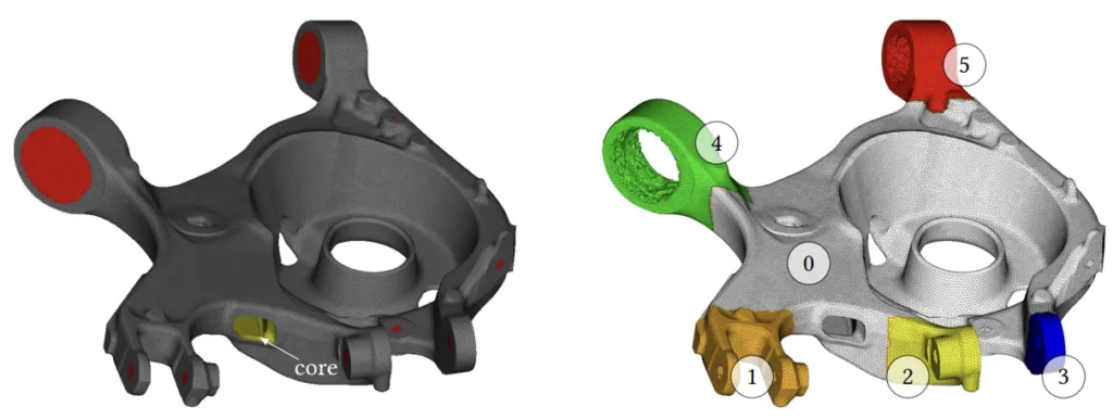
(b) mesh, critical area IDs CAID 0–5, only fullymachined (=evaluation) nodes visible
Fig. 0.2: Exemplary feature detection and critical areas of a rear lower control arm (RLCA)
- 図 0.1: 自動 CAE ツールの概要 (Automatic CAE Tool overview)
- 図 0.2: リアロアコントロールアーム (RLCA) の模範的なフィーチャ検出と重要領域 (Exemplary feature detection and critical areas of a rear lower control arm (RLCA))
- 図 0.3: Solidification II のフィーダーおよびインレット配置における Solidification I 結果の模範的な引け巣気孔率 ℎ 評価 (Exemplary shrinkage porosity ℎ assessment of Solidification I results in feeder and inlet placement for Solidification II)
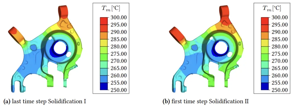
- 図 0.4: 鋳型温度 場の比較 (Comparison of mold temperature fields)
- 図 0.5: Solidification II の最終評価 (Final assessment of Solidification II)
- 図 0.6: Assessment II の模範的な出力テキストファイル (Exemplary output text file of Assessment II)
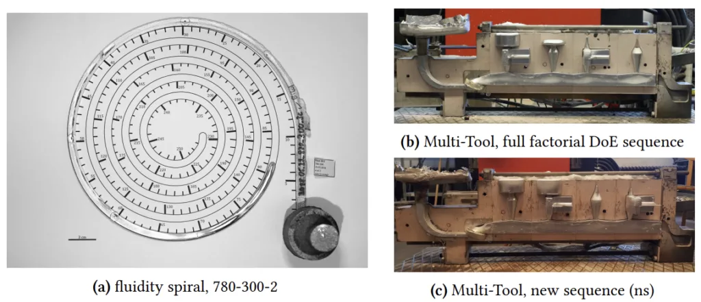
- 図 0.7: 注湯された形状、流動性スパイラル、および新しく開発されたマルチツールと 2 つの異なるシーケンス (The poured geometries, fluidity spiral and, the newly developed Multi-Tool with two different sequences)
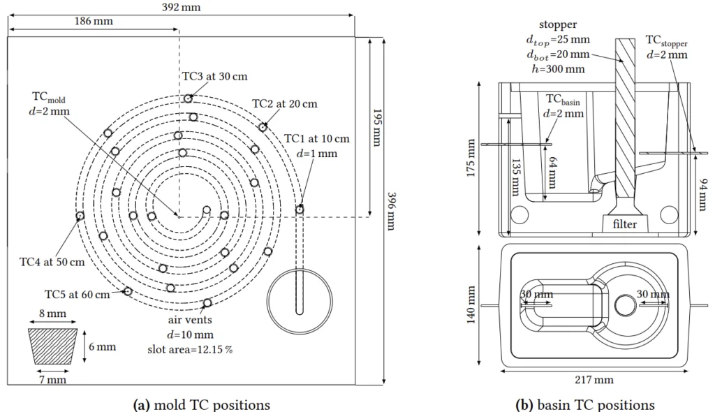
- 図 0.8: 流動性スパイラル鋳型の寸法と計測 (Fluidity spiral mold dimensions & instrumentation)
- 図 0.9: クロスおよびスピンドル寸法の概要 (Overview of cross and spindle dimensions)
- 図 0.10: 計測器を備えたマルチツールの設計 (Multi-Tool design with instrumentation)
- 図 0.11: マルチツールのサンプルと熱電対 TC ラベル定義 (Sample and thermocouples TC labeling definition for the Multi-Tool)
- 図 0.12: 温度キャリブレーション、実験値と計算値の温度 (Temperature calibration, experimental and calculated temperatures)
- 図 0.13: 計算された幾何学的流路長 ∗ とスパイラル長 の比較 (Comparison of calculated geometrical flow length ∗ and spiral length)
- 図 0.14: 実験とシミュレーションのスパイラル長比較 (Spiral length comparison of the experiments with the simulation)
- 図 0.15: 実験とシミュレーション間の Cf および Cp の充填度比較 (Filling degree comparison of Cf and Cp between experiment and simulation)
- 図 0.16: 異なる温度設定、水素指数 HI、欠陥体積 def のスピンドルとエアパイプ CT スキャン結果 (Spindle and cross with air pipe CT Scan results for different temperature setups)
- 図 0.17: フルファクトリアル DoE の Sp および Cp の計算された気孔率値 (Calculated porosity values for Sp and Cp of full factorial DoE)
- 図 0.18: 異なる FLCA 設計バリアント、肉厚 (Different FLCA design variants, wall thickness )
- 図 0.19: 最大幾何学的流路長 ∗ 、SDAS 、および臨界気孔数に対する FLCA 設計とマルチ/シングルインレットの影響 (FLCA design and multi-/single-inlet impact on maximum geometrical flow length ∗ , SDAS and number of critical pores)
- 図 0.20: 充填成功に対する FLCA 設計、マルチ/シングルインレット、解析的充填時間タイプ
∗ −
、および臨界固相率値 0.3–0.7 の影響 (FLCA design, multi-/single-inlet, analytical filling time type
∗ −
and critical solid fraction value 0.3–0.7 impact on filling success) - 図 0.21: RLCA 温度、解析的充填時間タイプ
∗ −
、および臨界固相率値 0.3–0.7 の充填成功への影響 (RLCA temperature, analytical filling time type
∗ −
and critical solid fraction value 0.3–0.7 impact on filling success) - 図 1.1: 鋳造 CAE アプローチ (Casting CAE Approach)
- 図 1.2: 本論文の作業パッケージは、開発 (I) とキャリブレーションおよび妥当性段階 (II) に分けられます (The thesis work packages are divided into development (I) and calibration and plausibility phase (II))
- 図 2.1: 模範的なアルミニウムシャーシ部品 (Exemplary aluminum chassis parts)
- 図 2.2: シャーシ部品の合金 (Alloys in chassis parts)
- 図 2.3: Al-Si 相図 (Al-Si phase diagram)
- 図 2.4: 永久鋳型セットアップの模式図 (Schematic illustration of permanent mold setup)
- 図 2.5: 流動性測定用の標準鋳型 (Standard molds for fluidity determination)
- 図 2.6: 異なる流動性スパイラル長の比較 (Comparison of different fluidity spiral lengths)
- 図 2.7: コーティングまたは鋳型の粗さ効果の模式的な視覚化 (Schematic visualization of the coating or mold roughness effect)
- 図 2.8: コーティングされた鋳型と溶融金属間の界面の模式図 (Schematic illustration of the interface between a coated mold and the melt)
- 図 2.9: 熱伝達係数 (HTC) の文献値 (Literature values for heat transfer coefficients (HTC))
- 図 2.10: デンドライト形成の模式図 (Schematic illustration of dendrite formation)
- 図 2.11: 文献からの A356 SDAS 対液相線時間 曲線 (A356 SDAS vs. liquidus time curves from literature)
- 図 2.12: 平均 SDAS ̄ (SDAS) に対する肉厚 の影響 (Impact of wall thickness on mean SDAS ̄ (SDAS))
- 図 2.13: 鋳造表面からの異なる距離での SDAS 値 (SDAS values at different distances from the casting surface)
- 図 2.14: 鋳型 ( ) および注湯温度 ( )、肉厚 および A356 の SDAS に対する位置の影響 (Mold ( ) and pouring temperature ( ), wall thickness and location impact on SDAS of A356)
- 図 2.15: 1 気圧での純アルミニウム中の水素溶解度 (Hydrogen solubility in pure aluminum at 1 atm)
- 図 2.16: A356 の収縮気孔率 (左) とガス気孔率 (右) の特性気孔率形態 (Characteristic pore morphology of shrinkage and gas pore for A356)
- 図 2.17: 異なる に関連するマクログラフでの気孔率結果 (Porosity results at macro-graphs related at different )
- 図 2.18: 気孔率に対する肉厚 の影響、ZL114A 合金板鋳造の CT 欠陥体積 def (Impact of wall thickness on porosity, CT defect volume def of ZL114A alloy plate casting)
- 図 2.19: 鋳造における幾何学的製造制約 (Geometric manufacturing constraints at castings)
- 図 2.20: 鋳造シミュレーションと最適化のステップ (Steps in casting simulation and optimization)
- 図 2.21: 箱型鋳造のゲートシステムバリアント (Gating systems variants of a box-shaped casting)
- 図 2.22: 高さ低減による段階的に改善された鋳造システムによる改善されたボトムゲートシステム (Improved bottom-gated system due to progressively improved casting system by height reduction)
- 図 2.23: 外側 (パイプ、シンクマーク) および内側 (マクロ、ミクロ) 気孔率などの収縮気孔率タイプの模式図 (Schematic illustration of the shrinkage porosity types such as external (pipe, sink marks) and internal (macro, micro) porosity)
- 図 2.24: 異なる初期速度で鋳型に入る溶融金属の模式図 (Schematic illustration of melt entering the mold at different initial velocities)
- 図 2.25: コントロールアームのフィーダー最適化により、歩留まりが向上 (Feeder optimization of a control arm resulted in better yield)
- 図 0.26: 総酸化物粒子量 total
oxid および鋳造部品の酸化物粒子 cast
oxid (Total amount of oxide particles total
oxid and oxide particles in cast part cast
oxid) - 図 2.27: [120] で使用された開発時間に関連する簡略化ステップ (Simplification steps used in [120] related to development time)
- 図 2.28: 最も簡略化されたバージョンと比較した完全バージョンの欠陥確率の尺度としてのホットスポット FSTime の比較 (Comparing the Hot Spots FSTime as a measure of defect probability of the complete version with the most simplified version)
- 図 2.29: 標準最適化と改善された最適化の凝固シミュレーション比較 (Solidification simulation comparison of standard and improved optimization)
- 図 2.30: 統合鋳造シミュレーション (Integrated casting simulation)
- 図 2.31: 統合計算材料工学 (ICME) の典型的なフローチャート (Typical flow chart of Integrated Computational Materials Engineering (ICME))
7. 結論:
主な調査結果の要約:
この研究では、アルミニウム重力ダイカストの自律的な実現可能性評価のための「自動 CAE ツール」を開発し、キャリブレーションに成功しました。このツールは、充填シミュレーションから純粋凝固解析への代替や 1D コンポーネントの利用などの効率向上手法を効果的に統合しています。実験的検証により、ツールの方向精度が確認され、特に HTC モデリングとガス気孔率予測に関して、さらなる改善の余地がある領域が特定されました。このツールは、設計バリアントとプロセスパラメータに対する感度を示しており、設計の初期段階の最適化に役立つ貴重な洞察を提供します。
研究の学術的意義:
この研究は、設計の初期段階における効率的な実現可能性評価の必要性に対処する、斬新な自動 CAE ツールを提供することにより、ダイカストの分野に貢献しています。キャリブレーションアプローチや効率向上手法の調査など、ツールの開発と検証方法論は、鋳造シミュレーションと MDO の研究者にとって貴重な洞察を提供します。この研究はまた、シミュレーションキャリブレーションのための正確なデータセットを取得するための現在の測定技術の限界を強調し、HTC モデリングとガス気孔率シミュレーションにおける将来の研究の方向性を示しています。
実際的な意味合い:
自動 CAE ツールは、ダイカスト業界に大きな実際的な意味合いをもたらします。それは以下を提供します:
- 手動による専門家の介入への依存を軽減し、より迅速かつ効率的な実現可能性評価を可能にします。
- MDO ワークフローへの統合、鋳造の実現可能性と品質のための設計バリアントの迅速な探索と最適化を促進します。
- 指向性がありながらも妥当な結果を設計の初期段階の意思決定に提供し、設計エンジニアを、実現可能で高品質な鋳造部品設計へと導きます。
- HTC モデリングやガス気孔率シミュレーションなど、さらなる研究開発の領域を強調することにより、より予測精度の高い CAE ツールの開発の基礎となります。
研究の限界と今後の研究分野:
この研究では、主に以下に関連する限界を認識しています。
- 不完全な指標範囲 (例えば、コスト面、サプライヤー施設の特性) により、CAE 評価は完全に予測可能ではなく、方向性のあるものとして考慮する必要があります。
- HTC の問題と Inspire Cast® でのガス気孔率シミュレーションの欠如による精度の限界。
- CAE モデリングに固有の簡略化。実験データに対するキャリブレーションと検証が必要です。
- シミュレーションキャリブレーションのためのより正確なデータセットを取得するための測定技術のさらなる改良の必要性。
今後の研究分野には以下が含まれます:
- 特にギャップ依存 HTC およびガス気孔率に関して、鋳造プロセスシミュレーションの未解決の問題に対する物理ベースの効率的な手法の開発。
- シミュレーション精度を向上させるための、異なる鋳造部品設計に対する HTC コンポーネントクラスの決定。
- プロセスパラメータと設計バリアントが気孔率形成に与える影響のさらなる調査。
- ローカルギャップサイズ関数として正確な HTC を提供するための熱機械シミュレーションと鋳造シミュレーションの結合の検討。
- より複雑な流れ現象と溶融金属挙動を処理するための CAE ツールの開発。
8. 参考文献:
- [1] Ahmadein, M.; Pustal, B.; Wolff, N.; BÜhRig-PolaczeK, A.: “Determination and verification of the gap dependent heat transfer coefficient during permanent mold casting of A356 aluminum alloy.” In: Materialwissenschaft und Werkstofftechnik 48.12 (2017), pp. 1249–1256.
- [2] AichbeRgeR, W.; RieneR, H.; DannbaueR, H.: “Regarding Influences of Production Processes on Material Parameters in Fatigue Life Prediction.” In: SAE Technical Paper. SAE International, 2007.
- [3] AKhtaR, S.; ARnbeRg, L.; Di Sabatino, M.; DispinaR, D.; SyveRtsen, M.: “A comparative study of porosity and pore morphology in a directionally solidified A356 alloy.” In: International Journal of Metalcasting 3.1 (2009), pp. 39–52.
- [4] AllaiRe, G.; Jouve, F.; Michailidis, G.: “Molding direction constraints in structural optimization via a level-set method.” In: Variational Analysis and Aerospace Engineering. Springer, 2015, pp. 1–39.
- [5] Allison, J.: “Integrated Computational Materials Engineering: A Perspective on Progress and Future Steps.” English. In: JOM 63.4 (2011), pp. 15–18.
- [6] Allison, J.; Li, M.; WolveRton, C.; Su, X.: “Virtual aluminum castings: An industrial application of ICME.” In: JOM 58.11 (2006), pp. 28–35.
- [7] AltaiR EngineeRing, Inc: Altair HyperMesh™ – High-Fidelity Finite Element Modeling. 2019.
- [8] AltaiR EngineeRing, Inc: Altair HyperView™ – CAE Results Visualization and Reporting. 2019.
- [9] AltaiR EngineeRing, Inc: Altair SimLab™ – Multiphysics Workflows with CAD Associativity. 2020. uRl: https://www.altair.com/simlab/ (visited on 12/08/2020).
- [10] AltaiR EngineeRing, Inc: Show Simulation Results. 2019. uRl: https://solid%5Cthink%5C-ing.com/helpst/2019.2/cast/en_us/topics/cast/analysis/view_simulation_results_t.htm#view_simulation_results_t (visited on 11/26/2019).
- [11] AmeRican FoundRy Society: Aluminum Permanent Mold Handbook. Des Plaines, Illinois, 2001.
- [12] Anastasiou, K. S.: “Optimization of the aluminium die casting process based on the Taguchi method.” In: Proceedings of the Institution of Mechanical Engineers, Part B: Journal of Engineering Manufacture 216.7 (2002), pp. 969–977.
- [13] “356.0 and A356.0: Al-Si-Mg High-Strength Casting Alloys.” In: Properties and Selection of Aluminum Alloys. Ed. by AndeRson, K.; WeRitz, J.; Kaufman, J. G. ASM International, 2019.
- [14] ASM: “Al (Aluminum) Binary Alloy Phase – Diagrams, Alloy Phase Diagrams.” In:ASM Handbook. Vol. 3. ASM International, 2016, pp. 113–139.
- [15] ASTM InteRnational: E155-15. Reference Radiographs for Inspection of Aluminum and Magnesium Castings. Standard. 2015.
- [16] ASTM InteRnational: E2422-17. Digital Reference Images for Inspection of Aluminum Castings. Standard. 2017.
- [17] Baez, J. C.; Gonzalez, C.; Chavez, M. R.; CastRo, M.; JuaRez, J.: “Fourier thermal analysis of the solidification kinetics in A356/SiCp cast composites.” In: Journal of Materials Processing Technology 153-154 (2004). Proceedings of the International Conference in Advances in Materials and Processing Technologies, pp. 531–536.
- [18] BÄhR, R.; Rehse, C.; StRoppe, H.: “Auswirkung von Porosität auf Festigkeit und Lebensdauer von Gussteilen - theoretische Modellierung.” de. In: Deutscher Gießereitag 2014. 2014.
- [19] Bazhenov, V. E.; PetRova, A. V.; Koltygin, A. V.: “Simulation of Fluidity and Misrun Prediction for the Casting of 356.0 Aluminum Alloy into Sand Molds.” In: International Journal of Metalcasting 12.3 (2018), pp. 514–522.
- [20] BDG: P202. Volumendefizite von Gussstücken aus Aluminium-, Magnesium- und Zinkgusslegierungen. 2010.
- [21] BDG: P203. Porositätsanalyse und -beurteilung mittels industrieller Röntgen-Computertomographie (CT). 2019.
- [22] Beganovic, T.: “Evolution im Aluminium-Guss von Fahrwerk-Komponenten.” PhD thesis. Fakultät für Werkstoffwissenschaft und Werkstofftechnologie der Technischen Universität Bergakademie Freiberg, 2016.
- [23] BETA Simulation Solutions: ANSA – The advanced CAE pre-processing software for complete model build up. 2018.
- [24] BETA Simulation Solutions: META – The high performance multi-disciplinary CAE post-processor. 2018.
- [25] Biancolini, M. E.: “Mesh Morphing and Smoothing by Means of Radial Basis Functions (RBF).” In: Handbook of Research on Computational Science and Engineering. IGI Global, 2012, pp. 347–380.
- [26] Bonollo, F.; Timelli, G.; GRamegna, N.; B.Molinas: “Permanent Mold Casting of Aluminum Alloys: Correlation among Processing, Microstructure and Simulation.” In: Proceeding of 3ʳd International Conference High Tech Die Casting. 2006.
- [27] BousKa, O.: “The effect of different casting parameters on the relationship between flowability, mould filling capacity and cooling conditions of Al-Si alloys.” In: Metalurgija-Journal of Metallurgy 14 (2008), pp. 18–30.
- [28] BRabazon, D.; BRowne, D. J.; CaRR, A. J.: “Experimental investigation of the transient and steady state rheological behaviour of Al–Si alloys in the mushy state.” In: Materials Science and Engineering: A 356.1 (2003), pp. 69–80.
- [29] BRamann, H.; PavlaK, L.: “Innovatives Produktdesign und robuste Prozessauslegung durch virtuelles Experimentieren mit der Gießprozess-Simulation.” In:GIESSEREI 102.3 (2015), pp. 28–39.
- [30] BRamann, H.; LeinewebeR, L.; StuRm, J. C.: “Innovatives Produktdesign und robuste Prozessauslegung im Druckgießprozess mit Autonomous Engineering.” In: GIESSEREI 105.1 (2018), pp. 34–45.
- [31] BRandenbeRgeR, U.: Giess- und Anschnitttechnik nach Friedrich Nielsen. Ed. by BRandenbeRgeR, U. online. 2009.
- [32] BRandenbeRgeR, U. et al.: Sand- und -Kokillenguss aus Aluminium. Bundesverband der Deutschen Gießerei-Industrie (BDG), 2010.
- [33] BRůna, M.; SlÁdeK, A.; KuchaRčiK, L.: “Formation of porosity in Al-Si alloys.” In: ́ Archives of Foundry Engineering 12.1 (2012), pp. 5–8.
- [34] BRůna, M.; BolibRuchovÁ, D.; PastiRčÁK, R.: “Numerical Simulation of Porosity for Al Based Alloys.” In: 177 (2017), pp. 488–495.
- [35] BRunhubeR, E.: Leichtmetall- und Schwermetall-Kokillenguss. Schiele & Schön, 1966.
- [36] BÜhRig-PolaczeK, A.; Michaeli, W.; SpuR, G.: Handbuch Urformen. Carl Hanser Verlag GmbH & Co. KG, 2013.
- [37] Cabannes, P. M.; FoRRest, R.; MuRatoRe, G.; RÖdteR, H.; GagnÉ, M.: Gusseisen mit Kugelgraphit - Das Wichtigste über Anschnitt und Speisertechnik. Rio Tinto iron & Titanium Inc., 2002.
- [38] CaliaRi, D.; Timelli, G.; Bonollo, F.; AmalbeRto, P.; GioRdano, P.: “Fluidity of aluminium foundry alloys: Development of a testing procedure.” In: Metallurgia Italiana 107.6 (2015), pp. 11–18.
- [39] Cambell, J.; HaRding, A.: “3201: Introduction to Casting Technology.” In: TALAT Lecture. Birmingham: EAA – European Aluminium Association, 1994.
- [40] Campbell, J.: “Invisible macrodefects in castings.” In: Le Journal de Physique IV 3.C7 (1993), pp. 861–872.
- [41] Campbell, J.: “Review of fluidity concepts in casting.” In: Cast Metals 7 (4 1995), pp. 227–237.
- [42] Campbell, J.: “Chapter 10 - The 10 Rules for Good Castings.” In: Complete Casting Handbook (Second Edition). Ed. by Campbell, J. Second Edition. Boston: Butterworth-Heinemann, 2015, pp. 535–638.
- [43] Campbell, J.: “Chapter 11 - Filling system design fundamentals.” In: Complete Casting Handbook. Ed. by Campbell, J. Oxford: Butterworth-Heinemann, 2011, pp. 741–756.
- [44] Campbell, J.: “Chapter 2 - Entrainment.” In: Complete Casting Handbook. Ed. by Campbell, J. Oxford: Butterworth-Heinemann, 2011, pp. 19–103.
- [45] Campbell, J.: “Chapter 3 - Flow.” In: Complete Casting Handbook. Ed. by Campbell, J. Oxford: Butterworth-Heinemann, 2011, pp. 105–153.
- [46] Campbell, J.: “Chapter 4 - Molds and cores.” In: Complete Casting Handbook. Ed. by Campbell, J. Oxford: Butterworth-Heinemann, 2011, pp. 155–186.
- [47] Campbell, J.: “Chapter 5 - Solidification structure.” In: Complete Casting Handbook. Ed. by Campbell, J. Oxford: Butterworth-Heinemann, 2011, pp. 187–253.
- [48] Campbell, J.: “Chapter 6 - Casting alloys.” In: Complete Casting Handbook. Oxford: Butterworth-Heinemann, 2011, pp. 255–390.
- [49] CaRl Zeiss MicRoscopy GmbH: AxioVision 4 Modul MosaiX. 2019. uRl: https : / / www.micro-shop.zeiss.com/de/de/system/axiovision+software/software+axiovision/module+biomed%252Fmat/000000-1235-913 (visited on 11/18/2019).
- [50] CaRlson, K. D.; BecKeRmann, C.: “Prediction of Shrinkage Pore Volume Fraction Using a Dimensionless Niyama Criterion.” In: Metallurgical and Materials Transactions A 40.1 (2009), pp. 163–175.
- [51] Chen, R.; Shi, Y.-F.; Xu, Q.-Y.; Liu, B.-C.: “Effect of cooling rate on solidification parameters and microstructure of Al-7Si-0.3Mg-0.15Fe alloy.” In: Transactions of Nonferrous Metals Society of China 24.6 (2014), pp. 1645–1652.
- [52] Chen, R. et al.: “Correlation of solidification microstructure refining scale, Mg composition and heat treatment conditions with mechanical properties in Al-7Si-Mg cast aluminum alloys.” In: Materials Science and Engineering: A 685 (2017), pp. 391–402.
9. 著作権:
- この資料は、"[Marcus Schopen]" の論文です: "[An Automatic CAE Tool for autonomous feasibility assessment of aluminum gravity die castings – development and calibration]" に基づいています。
- 論文ソース: 10.18154/RWTH-2022-07470
この資料は上記の論文に基づいて要約されたものであり、商業目的での無断使用は禁止されています。
Copyright © 2025 CASTMAN. All rights reserved.