고효율 유도 전동기 설계 다이캐스팅 구리 로터
Francesco Parasiliti, Marco Villani
Department ofElectric Engineering, University ofL'Aquila, 67040 L'Aquila, Italy
Abstract
The paper deals with the use of copper cage in three-phase low voltage induction motors and gives a design guideline to optimize their efficiency, according to the new European classification scheme. An accurate motor design allows to
"move" the motor from lower to upper efficiency classes without affecting the starting performance.
Korea Abstract
이 논문은 3상 저전압 유도 전동기에서 구리 케이지의 사용을 다루고 새로운 유럽 분류 체계에 따라 효율을 최적화하기 위한 설계 지침을 제공합니다. 정확한 모터 설계를 통해 시동 성능에 영향을 주지 않고 모터를 낮은 효율 등급에서 높은 효율 등급으로 "이동"할 수 있습니다.
Introduction
The European Committee of Manufacturers of Electrical Machines and Power Electronics (CEMEP) and the European Commission have agreed to a joint classification scheme that enables all OEMs (Original Equipment Manufacturers) and the other customers and users ofinduction motors to have a simple appreciation of the efficiency of this component [1].
This agreement should stimulate the Manufacturers in the development of new ranges of high efficiency motors that requires an accurate motor design [2], the adoption of new materials (e.g. premium steel [3]) and innovative technologies. It is well known that incorporation of copper for the rotor bars and end rings in place of aluminum would result in attractive improvements in motor energy efficiency.
Tool steel moulds as used for the aluminum die casting process have proved to be entirely inadequate when casting higher melting point metals including copper. Lack of a durable and cost effective mould material has been the technical barrier preventing manufacture ofthe copper cast rotor. In order to win acceptance by motor manufactures, they need to be produced with the same equipment that is currently in place and the copper industry has to find a way to deal with the thermal difference between molten copper and conventional technology and its effect on die life.
Few years ago, a consortium of USA partners has been assembled, having the aim to design, fabricate and demonstrate moulds suitable to withstand the copper motor rotor die casting environment for an economically acceptable life. Advances are being made and availability of durable and cost effective mould materials is expected in the next future [4], [5], [6].
The adoption of die-casting copper rotor, requires obviously to review the motor design criteria. Moreover, because the starting torque is proportional to its rotor resistance, the starting performance specifications tend to limit the amount by which the rotor ohmic loss can be reduced in favor of efficiency. For this reason, particular attention has to paid to the new motor design in order to ensure "feasible replacement".
Manufacturers are careful to follow designs that retain the critical elements of motor performance necessary to function within starting torque, starting current, breakdown torque, temperature considerations and other pertinent motor performance requirements. By maintaining these standards, replacement motors do not risk incompatibility with the current applications.
The authors have deeply investigated the use of copper rotor cage and have developed a design guideline to optimize the efficiency in three-phase low voltage induction motors, by choosing several design strategies: the simple substitution of copper for aluminum has been tested, then the motor with copper cage has been optimized by changing accurately some motor dimensions.
This activity falls in a research program supported by the MIUR (Italian Ministry for Education, University and Research) and concerning the analysis of motors and drives energy efficiency increase in industrial and civil applications.
The Substitution of Copper for Aluminum
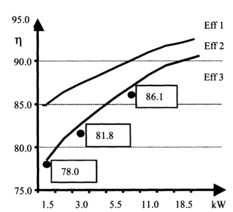
A first analysis has concerned the evaluation of motor performance by substituting copper for aluminum, without chancing neither the electrical steel or overall design ofmotor: this test has allowed to verify the achievable efficiency according to the European classification scheme (Fig. I).
Three low power sizes have been chosen, and particularly: 1.5,3 and 7.5 kW, 4 pole, 50 Hz, 400 V, TEFC, single-cage rotor. These motors, represent commercial motors with aluminum cage rotor and are typical motors produced by European manufacturer: their rated efficiencies belong to the Class Eff 3 (Fig. I) and they can be labeled "Low efficiency motors".
The motor performance have been evaluated by an analytical procedure where the physical description of the motor is reduced to equivalent parameters such as resistance and inductances: the adopted model takes into account the influence of saturation on stator and rotor reactances and the influence ofthe skin effect on rotor parameters.
The effects ofthe temperature on motor are computed on the basis of a detailed lumped-parameters thermal model. The validity of the mathematical model has been verified by means of experimental tests on several three-phase induction motors.
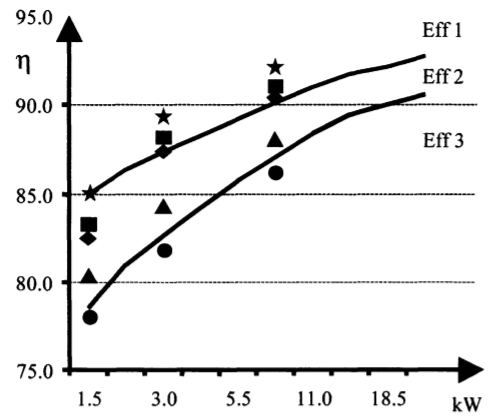
The results concerning the substitution of copper for aluminum are shown in the Tables 1, 2 and 3 (see the column "initial"): for the evaluation of active material cost, the following average costs have been assumed: 0.62 €/kg for the electrical steel, 3.13 €/kg for the stator winding, and 1.90 and 2.60 €/kg respectively for the aluminum and copper die-casting (in this analysis, the additional cost for the copper die-casting and moulds have not been taken into account). It is evident an efficiency improvement that allows to move all sizes from the class Eff 3 to the class Eff 2 (see the triangular symbols in Fig. 2): this is due mainly to a significant reduction oflosses in rotor bars of 50%. Moreover, the motor with cooper die-cast rotor has slightly lower line current and stator winding losses, light higher breakdown torque and good power factor: as drawbacks, it has poor starting performance. In fact, it is evident a slight increase ofstarting currents (about 7% for the small size and 4% for the others) and a drastic reduction ofstarting torque (13% for the 1.5 kW, 21 % for the 3.0 kW and 25% for the 7.5 kW).
The Optimized Design of Induction Motors with Copper Squirrel-Cage
Further improvement on motor performance can be achieved if the substitution of copper for aluminum is associated with an accurate motor design that allows to exploit the advantages of a copper cage, without affecting the starting performance. Moreover, it is interesting to evaluate the achievable improvement on the efficiency according to the European classification scheme. The additional costs associated with making higher efficiency motors, compared to standard efficiency motors, will vary between companies and design strategies: the biggest differences will be between those companies that base High Efficiency Motors on existing standards designs and those which use completely new designs and tool replacements. For this reason three strategies have been introduced respect to the amount ofthe additional cost, each of one affects the number of design variables for the optimization procedure. They are labeled as follows:
SI) copper cage + new stack length and stator winding;
S2) S1 + change oflamination;
S3) S2 + change of all motor dimensions, and stator diameters.
In the first case (S1) the stator and rotor slots dimensions and the inner and outside stator diameter are unchanged. The challenge is to physically fit more active material into the motor to reduce iron and copper losses. The cost of tooling for the new designs is effectively the same ofthe traditional design since the need for costly new lamination punch tools or stator housing tools are avoided (except the additional cost for copper die-casting).
The second case (S2) foresees also the change of lamination (stator and rotor slots dimensions) and this requires a renewal of the lamination tooling even if the inner and outside stator diameters are unchanged. The third and more expansive level (S3) requires to change all motor dimensions, inner and outside stator diameters included.
In this case a final option is the use of a larger frame size with modification ofthe existing housing. It is important to underline that in all strategies, the change of electrical steel has not been foreseen and it is the same ofthe original design: moreover, the variables "Stack length", "Outside Stator Diameter" and "Inner Stator Diameter" have been varied with reference to "normalized values" only, according to the Manufacturer suggestions.
Several constraints have been introduced that concern the typical motor performance but above all the starting performance. For each optimization, a low cost motor design was involved by means of an appropriate algorithm developed by the authors [7]; the optimization was formulated as constrained maximization of the objective function "rated efficiency" expressed in terms of the motor design variables.
Results
The final results for the optimized designs with copper cages are summarized in Tables 1, 2 and 3: they show the main geometric dimensions, the motor performance, the weight and the cost of active materials. The first comment concerns the efficiency values whose differences, respect the original design with aluminum rotor, are shown in Tab.4: it is evident a gradual increase that allow to move the motors toward the upper efficiency class Eff 1. The efficiency values of new motors with reference to the European classification scheme have been reported in Fig. 2. For the 1.5 kW motor (Tab. 1), the strategies S1 and S2 give rise to new designs that are within the Eff 2 class and only with S3 has been possible to achieve the lower limit of the Eff I class: this is due to the available dimensions on stator di-ameters, stack length and housing, that have not allowed "further movements". Obviously, the use of a "premium steel" combined with an accurate motor design allows, for this size, to reach easily the Eff I class. For the other sizes (Tab. 2 and 3), it is evident how the solution SI is sufficient to move the motors in the Eff I class, and even with S2 and S3 highest levels can be reached. It is important to underline that all these movements have been achieved without chancing the electrical steel (that is without using any "premium steel").
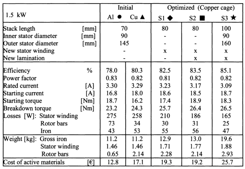
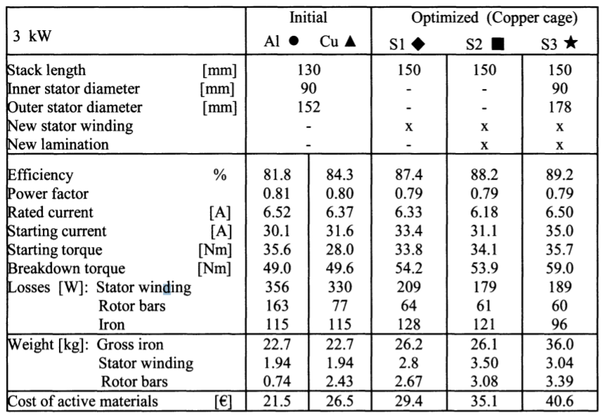
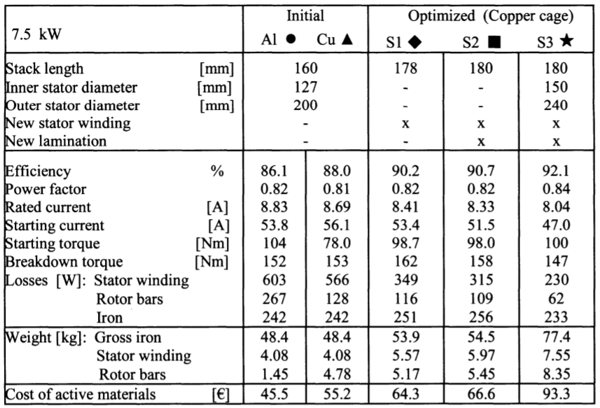
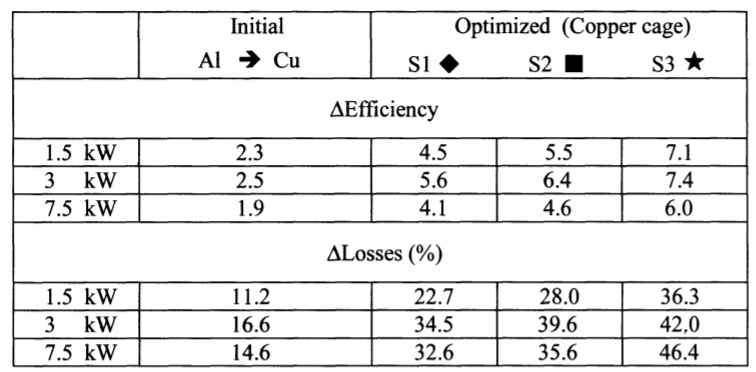
The percent difference on total losses are shown in Tab.4: the significant losses reduction led to lower temperature on rotor and stator windings and it means that smaller internal cooling fans can be employed with effect in reducing the friction and windage losses. Moreover, motor temperatures translate directly to motor life and maintenance costs. The new motors present a reasonable breakdown torque, starting torque and starting current: particularly, the optimization algorithm has found new designs with a starting torque comparable respect the initial design with aluminum rotor ones. The increase on active material cost is due mainly to the use of copper in the rotor bars and the increase of amount of iron in the stator and rotor core. The comparison of the optimized designs with the initial one with copper cage, points out how the designs S1 and S2 present a reasonable cost even if, for the 1.5 kW, these solutions do not guarantee the achievement ofthe upper class Eff 1. It is important to underline that, in the proposed examples, the active material costs represent 30+40% of manufacturing costs (active material, labor and structure costs): consequently, the increases on the active material costs reflect on an increase on tpanufacturing costs whose percentages are in the range 10+50% (the higher values correspond to the S3 designs).
Conclusions
Copper rotor motors could be the next step in a steady line of motor efficiency improvements and may be able to achieve highest efficiency values according to the European classification scheme. The proposed examples point out how the design strategies reflects significantly on efficiency and allow to "move" the motor from lower to upper efficiency classes. Starting from the Eff 3 class, the use of copper in place of aluminium, allows to reach the Eff 2 class, but the starting performance are very poor, with a significant reduction on starting torque (up to 25%). The highest efficiency level Eff 1 can be achieved by a design optimization of copper cage motor, and this result can be achieved with low additional costs. Obviously, these improvements are affected by the cost for the copper diecasting and the cost of mould material and these aspects represent now technical barriers preventing manufacture ofthe copper cast rotor. If advances will be done on availability of durable and cost effective mould materials, the motors with diecasting copper rotor will gain certainly more and more interest in the future European market that shall require only energy efficiency induction motors.
References
[1] P. Bertoldi, "EU/CEMEP Classification Scheme for Motors and Negotiated Agreement", Energy Efficiency Improvements in Electric Motors and Drive, Springer, June
2000, ISBN: 3-540-67489-6, pp. 369-375
[2] F.Parasiliti, M.Viliani "Evaluation ofthe Design Options and Cost Impact of Improving Motor Efficiency", Energy Efficiency Improvements in Electric Motors and Drive,
Springer, June 2000, ISBN: 3-540-67489-6, pp. 514-528.
[3] F. Parasiliti, M. Villani "Technical and economical evaluation of electrical steels for
high efficiency motors", Transworld Research Network, Recent Res. Devel. Magnetics, n. 2 (2001), pp. 47-54.
[4] Dale T. Peter "Die-Casting Background", Die-Casting Copper Motor Rotor: Workshop
and Technology Demonstration, CDA-Copper Development Association, Denver
(USA), January 2002.
[5] E. Brush "Rotor Die-Casting in Copper To Date", Die-Casting Copper Motor Rotor:
Workshop and Technology Demonstration, CDA-Copper Development Association,
Denver (USA), January 2002.
[6] A.Ansel, O.Walti, J.F.Brudny, "Influence of copper pressure die-casting on induction
machine magnetic behaviour", International Conference on Electrical Machines,
(lCEM), Helsinki, September 2000.
[7] A. Daidone, F. Parasiliti, M. Villani, S. Lucidi, "A New Method for the Design Optimization of Three-Phase Induction Motors", IEEE Transaction on Magnetics, 34
(1998), pp. 2932-2935.
This work was developed in the ambit ofthe COFIN 2001 Program and supported
by MIUR (Italian Ministry for Education, University and Research).