Semi-solid Processing of Alloys
本技術概要は、David H. Kirkwood、Michel Suéry、Plato Kapranos、Helen V. Atkinson、Kenneth P. Youngによる学術論文「Semi-solid Processing of Alloys」(Springer Series in Materials Science 124、2010年)に基づいています。

キーワード
- 主要キーワード: 半固体加工
- 副次キーワード: チクソフォーミング, レオキャスティング, 合金加工, 微細構造, 粘度, ダイカスト, アルミニウム合金, マグネシウム合金, チクソトロピー
エグゼクティブサマリー
- 課題: 従来の鋳造・鍛造プロセスでは、ガス巻き込みや引け巣などの欠陥が発生しやすく、高品質なニアネットシェイプ部品の製造には限界がありました。
- 手法: 半固体加工(SSP)は、合金を固液共存状態で攪拌・制御し、樹枝状晶(デンドライト)を破壊して球状の固体粒子を液体中に分散させることで、材料の流動性を劇的に向上させます。
- 主要なブレークスルー: このプロセスにより、層流充填が可能となり、ガス巻き込みが大幅に減少し、熱処理可能な高密度・高品質部品の製造が実現します。
- 結論: 特に近年のレオキャスティング技術の進化により、従来の高コストという課題が克服されつつあり、半固体加工は自動車部品や電子機器筐体などの分野で、コスト効率の高い高性能部品製造技術としての地位を確立しています。
課題:なぜこの研究がHPDC専門家にとって重要なのか
従来の高温液体金属を用いる鋳造法、特に高圧ダイカスト(HPDC)では、高速で金型に射出するため、溶湯が飛散しやすく、ガスを巻き込みやすいという本質的な課題を抱えています。これにより製品内部に鋳巣(ポロシティ)が発生し、熱処理(T6処理など)を行うとブリスター(膨れ)が生じるため、熱処理による機械的特性の向上が困難でした。また、凝固収縮による引け巣も品質を低下させる一因です。これらの課題は、特に高い信頼性や疲労強度が求められる自動車の重要保安部品や構造部品の製造において、大きな制約となっていました。半固体加工は、これらの根本的な問題に対する画期的な解決策として1970年代初頭にMITで発見され、研究開発が進められてきました。
アプローチ:手法の解明
半固体加工は、合金が液体から固体へと凝固する途中の「半固体」状態の特異な性質を利用します。この状態の合金に剪断力(攪拌)を加えると、樹枝状に成長するデンドライト組織が破壊され、球状の固体粒子が液体中に分散したスラリーとなります。このスラリーは、静置状態では高い粘度を示しますが、力を加えると粘度が劇的に低下する「チクソトロピー」という特性を持ちます。この性質を利用することで、金型内を乱流なく、穏やかに層流で充填することが可能になります。
手法1:チクソフォーミング(Thixoforming) 特殊な製造法(例:電磁攪拌法)で予め球状組織を持つビレット(素材)を製造し、それを再加熱して半固体状態に戻してから金型に射出・成形する手法です。高品質な部品が製造できますが、特殊なビレットが高価であること、工程内でのスクラップの再利用が難しいことなどが課題でした。
手法2:レオキャスティング(Rheocasting) 溶融した金属から直接、成形機側で半固体スラリーを生成し、そのまま金型に射出・成形する手法です。特殊なビレットが不要で、一般的なインゴットから製造でき、コストを大幅に削減できる可能性があります。本書で紹介されているUBEのNRCプロセスやMITのSSRプロセスなどは、このレオキャスティングの最新技術であり、半固体加工の普及を加速させる鍵として注目されています。
ブレークスルー:主要な発見とデータ
本書は、半固体加工に関する40年近くにわたる研究開発の成果を網羅的にまとめており、特に以下の2点が重要なブレークスルーとして挙げられます。
発見1:微細構造制御による劇的な粘度低下と層流充填の実現
半固体状態の合金に剪断力を加えることで、デンドライト組織が球状化し、見かけの粘度が劇的に低下する「チクソトロピー」現象が、金属合金で初めて確認されました。本書の序文によれば、この発見が半固体加工の全ての始まりです。例えば、Sn-Pb合金を用いた初期の研究(第6章)では、攪拌された半固体スラリーは、攪拌されていないものに比べてはるかに低い粘度を示すことが示されました。この低い粘性とチクソトロピー性により、金型内を穏やかな層流で充填でき、従来のダイカストで問題となっていたガス巻き込みを90%以上削減し、ポロシティのない健全な鋳造品を得ることが可能になります。これにより、従来は不可能とされた鋳造部品へのT6熱処理が実現し、機械的特性が飛躍的に向上しました。
発見2:新レオキャスティング技術によるコスト障壁の克服
チクソフォーミングの最大の課題は、電磁攪拌などで製造された特殊な原材料ビレットの高コストでした。本書の第4章および第10章では、この問題を解決するための新しいスラリー生成技術が詳述されています。例えば、MITで開発されたSSR(Semi-Solid Rheocasting)プロセスでは、回転する冷却ロッド(コールドフィンガー)を溶湯に挿入し、急冷と攪拌を同時に行うことで、微細な球状粒子を大量に生成します。この方法では、高価なビレットが不要となり、一般的なインゴットから直接、成形現場でスラリーを製造できます。これにより、材料コストの削減と工程内スクラップの再利用が可能となり、従来のダイカストとの直接的なコスト競争力を持つ道が開かれました。
研究開発および製造オペレーションへの実践的示唆
- プロセスエンジニア向け: 本研究は、半固体スラリーの粘度が固体率、冷却速度、剪断速度に強く依存することを示しています(第6章)。安定した品質を確保するためには、特に射出前のスラリー温度(固体率に直結)と射出速度の厳密な管理が不可欠です。
- 品質管理チーム向け: 付録の機械的特性データは、同じ合金(例:A356)でも、熱処理条件(T5、T6)や製造元によって引張強度や伸びが大きく異なることを示しています。これは、最終製品の品質保証において、製造履歴と熱処理条件のトレーサビリティがいかに重要であるかを物語っています。
- 設計エンジニア向け: 第12章で詳述されているように、半固体加工部品の設計では、シャープな角を避け、適切な抜き勾配とRを設けることが重要です。また、層流充填という特性を活かし、ガスの最終充填箇所を予測して効果的なベントや真空バルブを配置する金型設計が、欠陥のない製品を得る鍵となります。
論文詳細
Semi-solid Processing of Alloys
1. 概要:
- タイトル: Semi-solid Processing of Alloys
- 著者: David H. Kirkwood, Michel Suéry, Plato Kapranos, Helen V. Atkinson, Kenneth P. Young
- 出版年: 2010
- 学術誌/学会: SPRINGER SERIES IN MATERIALS SCIENCE 124
- キーワード: Semi-solid processing, Rheocasting, Thixoforming, Alloys, Microstructure, Rheology, Modeling, Industrial applications
2. 抄録:
半固体金属学(SSM)は、その概念の確立から約37年が経過し、着実な研究の進展と産業応用の開始が見られる。SSM分野は、主に「レオキャスティング」と「チクソキャスティング」に分類される多数のプロセスルートで構成される。前者は液体金属から始まり、部分凝固中の攪拌を経て成形に至る。後者は適切な組織を持つ固体金属から始まり、所望の固相率まで加熱して成形する。過去37年間の研究、特に最近10年間の研究により、プロセスの基礎に関する詳細な知見が得られ、多様なSSMプロセスと技術革新が生まれた。本モノグラフは、半固体加工の基礎となる微細構造の発生と設計、合金スラリーのレオロジーとモデリング、そして原材料からプロセス制御、部品設計、実用化に至るまでの産業応用について、三部構成で包括的に解説するものである。
3. 序論:
半固体加工は、1972年にSpencer、Mehrabian、Flemingsによって発表された、凝固中のスズ-鉛合金の粘度挙動に関するMITでの研究に端を発する。当初の目的は凝固割れのメカニズム解明であったが、凝固中に剪断を加えることでデンドライト組織が球状化し、粘度が劇的に低下する「チクソトロピー」現象が金属系で初めて発見された。この発見は、攪拌された半固体合金をダイカストのように金型に射出できる可能性を示唆し、ガス巻き込みの低減や凝固後の微細な等軸晶組織による機械的特性の向上といった利点をもたらすものとして、合金のチクソトロピー性に関する詳細な研究の引き金となった。過去40年間にわたる世界中の研究機関や産業界での研究はこれらの期待を裏付けるものであり、現在では自動車、電子、通信産業向けにアルミニウムおよびマグネシウム合金のチクソフォーム部品を製造する産業が隆盛している。
4. 研究の概要:
研究トピックの背景:
従来の鋳造法における、乱流によるガス巻き込み、凝固収縮による引け巣、デンドライト組織に起因する機械的特性の限界といった課題。
従来の研究の状況:
1972年のMITによるチクソトロピー現象の発見以来、チクソフォーミング(ビレット再加熱法)が主流として発展。しかし、特殊ビレットの高コストとスクラップ再利用の問題が普及の障壁となっていた。
研究の目的:
半固体合金加工に関する基礎科学から最新の産業技術までを体系的に整理し、微細構造の制御、レオロジー特性、数値モデリング、および多様な工業的応用例を包括的に提供することを目的とする。
中核研究:
本研究は、3つのパートから構成されるモノグラフである。 - パートI:半固体合金における微細構造の進化と設計: 核生成、デンドライト破砕、等軸晶の成長と球状化といった基礎的側面から、スラリーの微細構造評価、等温保持中の組織変化、最新のスラリー生成技術開発までを扱う。 - パートII:レオロジーとモデリング: 部分凝固および部分再溶解した合金の粘度、流動性、降伏応力などのレオロジー的挙動を実験的に決定する方法を詳述する。さらに、これらの挙動を予測するための1相および2相流体モデル、有限差分法、有限要素法を用いた数値モデリング技術について解説する。 - パートIII:半固体加工の産業応用: MHD法による原材料製造から、最新のレオキャスティング技術、射出成形プロセス制御、金型設計、部品設計規則、そして自動車、電子機器、その他分野での具体的な実用例と将来展望までを網羅する。
5. 研究方法論
研究デザイン:
本稿は、特定の実験的研究ではなく、半固体加工の分野における約40年間の基礎研究および応用研究の成果を編纂、レビュー、体系化したモノグラフである。その構成は、科学的基礎から工学的応用へと段階的に進むように設計されている。
データ収集と分析方法:
著者は、隔年で開催される「International Conference on Semisolid Processing of Alloys and Composites」の論文集、関連する学術雑誌、および産業界の技術報告書から、半固体加工に関する広範な文献を収集し、分析した。データは、微細構造写真、レオロジー測定データ、機械的特性試験結果、数値シミュレーション結果など多岐にわたる。
研究トピックと範囲:
研究範囲は以下の通りである。 1. 基礎理論: 合金系の平衡、核生成、界面構造、形態不安定性など、半固体組織の形成に関する物理冶金学的基礎。 2. レオロジー特性: 粘度計を用いた粘度測定、流動性試験など、半固体スラリーの流動挙動の実験的評価。 3. 数値モデリング: 構造パラメータを用いたモデル、有限差分/有限要素法による1相/2相流体シミュレーションなど、成形プロセスを予測するための計算力学的手法。 4. 産業技術: 原材料(ビレット)の製造法、スラリー生成技術、プロセス制御、金型設計、およびアルミニウム、マグネシウム、銅、鉄鋼合金を用いた製品化事例。
6. 主要な結果:
主要な結果:
- 半固体加工の核心は、凝固中の剪断力によってデンドライト組織を破壊し、球状の固体粒子が液体中に分散したスラリーを形成することにある。これにより、見かけの粘度が劇的に低下するチクソトロピー性が発現する。
- 半固体スラリーのレオロジーは、固体率、剪断速度、保持時間に依存する複雑な非ニュートン流体挙動を示す。特に、剪断速度の増加に伴い粘度が低下する「剪断減粘」特性が顕著である。
- プロセスは大きく分けて、ビレットを再加熱する「チクソフォーミング」と、溶湯から直接スラリーを生成する「レオキャスティング」に分類される。歴史的にはチクソフォーミングが先行したが、コストとリサイクルの観点からレオキャスティング技術が近年再評価されている。
- 新しいレオキャスティング技術(例:NRC、SSR)は、成形現場で高品質なスラリーを低コストで生成することを可能にし、半固体加工の経済性を大幅に改善した。
- 半固体加工は、層流充填によりガス巻き込みを最小限に抑えるため、T6などの熱処理が可能となり、従来の鋳造法では達成困難であった高い機械的特性(強度、延性、疲労特性)を持つ部品を製造できる。
- 成功する産業応用には、原材料の品質、スラリーの温度(固体率)管理、射出システム、そして厚肉ゲートや適切なベント配置といった、半固体加工に特化した金型設計が不可欠である。
Figure Name List:
- Fig. 1.1 Simple Binary Alloy Equilibrium Diagram
- Fig. 1.2 The effect of Cooling Rate on the fraction of Primary Solid formed
- Fig. 1.3 Free energy of growing embryo/nucleus
- Fig. 1.4 Homogeneous and heterogeneous nucleation rates as a function of undercooling
- Fig. 1.5 Cap of solid phase forming from the liquid on an impurity surface by heterogeneous nucleation
- Fig. 1.6 The bold line indicates the undercooling necessary for grain initiation. The free-growth undercooling is calculated; the nucleation undercooling is schematic only. Inset (1) shows the classical spherical-cap model for heterogeneous nucleation. Inset (2) shows a cap of α–Al growing on an inoculant particle through the critical hemispherical condition [5]
- Fig. 1.7 The number of grains per unit volume as a function of the number of refiner particles per unit volume, showing a general trend to lower efficiency at higher addition level. Data from grain diameters measured in TP-1 tests (closed circles) are compared with predictions of the free-growth model (open circles) [5]. The predictions are qualitatively different from those of Maxwell and Hellawell [6] and are a much better fit to the data [5]
- Fig. 1.8 Distribution of (a) solute and (b) temperature ahead of a moving planar interface showing the development of Constitutional Undercooling.
- Fig. 2.1 Schematic representation of complex Dendrite Structure, (a) 3D view (b) Cross Section.
- Fig. 2.2
- Fig. 3.1 (a, c, e) Conventional casting after 0 min, 5 min, and 15 h soaking, (b, d, f) MHD casting after 0 min, 5 min, and 15 h soaking
- Fig. 3.2 Microstructural changes in DC cast Al/7%Si Alloys during isothermal heat treatment at 580 degC.
- Fig. 3.3 Effect of Cold Work on particle spheroidisation (closed circles) compared to undeformed alloy (open circles).
- Fig. 3.4 Observations of neck representative of trend with unequal sized particles
- Fig. 3.5 Observations of neck representative of trend for equal sized particles
- Fig. 3.6 Variation of the average solid particle volume and equivalent radius with isothermal holding time
- Fig. 4.1 Schematic of the SSR process
- Fig. 4.2 Schematic of dendrite multiplication
- Fig. 4.3 Micrograph of Al–Cu alloy rheocast with SSR and then immediately quenched. Spheroidal primary grains are evident that formed during the initial period of solidification with subsequent dendritic microstructure that formed during the quench
- Fig. 4.4 Microstructures of reheated and quenched Al–Si alloy produced by (a) SSR and (b) electromagnetically stirred MHD continuous cast billet [35]
- Fig. 6.1 Devices used to measure the fluidity. (a) spiral; (b) vacuum suction
- Fig. 6.2 Apparent viscosity as a function of the solid fraction for an A356 alloy sheared at (filled square) 27 s−1, (open square) 54 s−1, (filled circle) 108 s−1, and (open circle) 216 s−1 during continuous cooling in the solidification interval at 1.2◦C min−1 (from [11])
- Fig. 6.3 Apparent viscosity as a function of shearing time at 590◦C of a A356 alloy (fs = 0.35) partially solidified with a shear rate of (filled square) 27 s−1, (open square) 54 s−1, (filled circle) 108 s−1, and (open circle) 216 s−1 (from [11])
- Fig. 6.4 Apparent viscosity as a function of shearing time at a shear rate of 200 s−1 and at various temperatures corresponding to solid fraction fs = 0.3 (open square), 0.4 (filled circle), and 0.5 (filled square). Al-4.5%Cu-1.5%Mg (from [12])
- Fig. 6.5 Apparent viscosity of an A356 alloy as a function of the shear rate for various solid fractions (from [3])
- Fig. 6.6 Variation of the apparent viscosity at steady state as a function of the volume fraction of solid increased by the liquid volume fraction entrapped in the agglomerates for various shear rates (from [15])
- Fig. 6.7 Effect of the resting time tr on the hysteresis loops of a Sn-15%Pb alloy; tu is the time required to increase the shear rate up to its maximum value (from [2])
- Fig. 6.8 Shear rate jumps from 0 to 100 s−1 after different rest times for Sn-15%Pb alloy at fraction solid 0.36 [23]
- Fig. 6.9 Apparent viscosity as a function of the isothermal shearing time of an A356 alloy partially solidified (fs = 0.35), (open circle) without and (filled circle) with 15% SiC particles added at time t = 0. The shear rate is 108 s−1 (from [11])
- Fig. 6.10 Fluidity Y of an Al-10%Cu alloy in the semisolid state characterized by a solid fraction gs. YL represents the fluidity of the liquid. The various curves are concerned with various stirring rates in revolutions/min. open circle: 340; open square: 482; open triangle: 695; star sqaure: 992 (from [25])
- Fig. 6.11 Schematic drawing of the vane viscometer; (a) complete viscometer; (b) crucible with thermocouple and vane; (c) four bladed vane
- Fig. 6.12 Schematic drawing of the drained oedometric compression apparatus used for Al alloys. From [37]. 1: I.R. lamp furnace; 2: piston; 3: filter support; 4: container; 5: specimen; 6: fabric of SiC Nicalon fibers; 7, 8: thermocouples
- Fig. 6.13 Schematic drawing of the drained triaxial compression apparatus. From [37]
- Fig. 6.14 Variation of the shear stress deduced from a compression test as a function of the isothermal holding time in the semisolid state before compression at 580◦C of an A357 alloy partially remelted (fs = 0.45). The compression rate is 0.01 s−1. From [11]
- Fig. 6.15 Variation of the shape factor of the globule as a function of the isothermal holding time in the semisolid state at 580◦C (fs = 0.45) of an A357 alloy continuously cast (open circle) without and (filled circle) with electromagnetic stirring. The dashed line corresponds to perfect spheres. From [11]
- Fig. 6.16 Viscosity as a function of the shear rate for two aluminum alloys (A356, A357) and a magnesium alloy (AZ91) showing the shear thinning behavior of the alloys at solid fractions fs close to 0.50. From [39]
- Fig. 6.17 Step changes of strain rate with increasing values (left) and decreasing values (right) for a Al-6%Si-0.6%Mg alloy deformed in compression at 580◦C leading to a solid fraction of 0.55. From [11]
- Fig. 6.18 Micrograph of a A356 + 20%SiC composite after partial remelting and quenching showing the position of the SiC particles in the eutectic mixture (liquid in the semisolid state). From [41]
- Fig. 6.19 Effect of a step change of strain rate in the case of a A356 + 20% SiC composite deformed in compression in the semisolid state. From [42]
- Fig. 6.20 Variation of the filtration pressure as a function of the liquid fraction remaining in the specimen during drained compression at various strain rates (from [46])
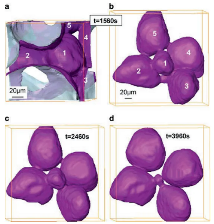
- Fig. 6.21 Microstructures of an Al-15.8%Cu alloy after solidification (left) and after partial remelting at 555◦C and holding for 80 min (right). These micrographs were obtained from in-situ tomography experiments carried out at ESRF Grenoble (from [50])
- Fig. 7.1 Aluminum alloy 7075 is being forced vertically upwards into a die (see inset). The material has to flow around a corner and liquid segregation is occurring at that corner [53], partly because the temperature conditions are inappropriate. The rectangular outlined portion is the area shown in the micrograph
- Fig. 7.2 Load versus displacement for the rapid compression of a billet of A357 aluminum alloy in a thixoformer [56], illustrating that at relatively high fraction solid (572◦C), the spheroids in the microstructure are deformed. At relatively low fraction solid (576◦C), the spheroids are undeformed and the resistance to deformation is low. The closeness of these temperatures shows how sensitive the process is to temperature. The microstructures are taken from the edge of the billet after compression has been completed
- Fig. 7.3 Numerical simulation of die filling [61]. (a) Partial filling of die. (b) Modeling simulation of (a) where white corresponds to dark on (a). (c) Modeling simulation with improved die design showing smoother filling
- Fig. 7.4 Comparison of the effect of thixotropic relaxation time when a droplet of Sn15wt%Pb is allowed to fall from rest onto a plate located 6 cm below [72]. The droplet is assumed to be at 197◦C with approximately 47% solid fraction. Heat transfer to the plate is taken into account. Relaxation times (in ms) from top to bottom are 1, 2, 5, 10, and 50. The first column on the left has a zero rate, i.e., constant viscosity. The second has thinning and thickening rates of 1,000 s−1. The third column has a 1,000 s−1 thinning rate and a 0.0001 thickening rate. The last column has infinitely fast rates
- Fig. 7.5 Impact of a viscous drop with the same material as for Fig. 6.5 [72]. Times in ms from top to bottom are 0, 1, 5, 50, 100. Surface tension is dominating the flow in the 5–50 ms period; gravity is dominant by 100 ms
- Fig. 7.6 Comparison between simulation of flow into a cavity with a round obstacle assuming Newtonian behavior and assuming thixotropic behavior [73]. The direction of flow is upwards
- Fig. 7.7 Models of shear rate jump from 50 to 70 s−1 in a 1 Pa.s Newtonian fluid in a rotational viscometer [75]. The implicit solver overestimates the width of the momentum diffusion peak
- Fig. 7.8 Shear rate jump from 1 to 100 s−1 in SnPb alloy (fs = 0.36) showing repeats of the same experiment and modeled fits using a spreadsheet and FLOW-3D predictions with a new ADI solver, which was introduced to address the challenges posed by fluids where the viscosity and shear rate change by many orders of magnitude in short times and spaces [76]
- Fig. 7.9 Experimental and modeled results (with FLOW3D) for compression tests on A356 aluminum alloy at two different temperatures [52]. For the higher temperature (578◦C), there is hardly any initial peak at the beginning of the curve
- Fig. 7.10 Die filling with semisolid Sn15%Pb (fs = 0.55) [69]. (a) Stepped die shape with the undeformed finite element mesh in place ready for deformation. (b) Part way through the deformation before die filling is completed showing the distribution of the structural parameter λ, with λ = 1 representing a structure, which is still fully agglomerated
- Fig. 7.11 The fluid front for die filling with different viscosity models [70]. (a) Newtonian showing break-up of the flow front, (b) shear-thinning viscosity with a smoother flow front profile, (c) internal variable viscosity again with a smoother profile but with some significant differences from (b)
- Fig. 7.12 Comparison between Newtonian (on the left) and Bingham (on the right) filling behavior for a three-dimensional cavity with a cylindrical obstacle [82]
- Fig. 7.13 Flow patterns found by modeling for a Bingham fluid in a two-dimensional cavity [84]
- Fig. 7.14 Map showing the flow patterns identified in Fig. 34, plotting Bingham number Bi versus Reynolds number Re [84]
- Fig. 7.15 Flow instability of the “toothpaste” type in semisolid processing. The metal is filling from the right to the left [88]
- Fig. 7.16 Comparison between experimental and simulated filling of a cavity (initial ram velocity 0.8 ms−1, diameter of tube 25 mm) [93]. (a) Fraction solid 0.52. (b) Fraction solid 0.58. (c) Fraction solid 0.73. In each figure, the upper part is the simulation and the lower part the experimental result obtained with interrupted filling. The material is flowing into the cavity from the left
- Fig. 7.17 (a) Cross-section through the semisolid material solidified in a tube in a Poiseuille-type experiment. The eutectic-rich concentric rings are due to veins of liquid formed in the shot sleeve. (b) shows such a vein formed at the limit of the dead zone in the shot sleeve (see inset). [93]
- Fig. 7.18 Isopotential curves used in the work by Zavaliangos [100] and compared with that in Martin, Favier and Suery [38]. (a) Constant liquid fraction fL and different levels of cohesion c (c is analogous to the structural variable λ), (b) constant cohesion and different fL, and (c) different fractions of liquid fL [38]. σc is the compressive stress and σh the hydrostatic pressure in the solid phase
- Fig. 7.19 Comparison between the simulated and the observed contours of the flow front for different filling velocities. The simulations have been carried out using one set of model parameters [101]
- Fig. 7.20 Solid fraction field in the component, based on chemical analysis of the amount of lead (left) vs. simulated solid fraction field. Experimental and numerical results for a piston velocity of 50 mm s−1 and an initial solid fraction of 62% with Sn15%Pb alloy [101]
- Fig. 7.21 Map of types of flow [107]. (a) Laminar, (b) Transient, (c) Turbulent. Bi is the Bingham number, Kc a rheological number, C1, C2 geometric constant and Re the Reynolds number. Kc, C1 and C2 are not specified in the paper
- Fig. 7.22 Three-dimensional process window for aluminum alloy A356 [107]. Mechanical properties are given in the two top boxes. The smaller boxes summarize the process parameter windows to obtain those mechanical properties (ΔT is the temperature window, Δfs the solid fraction window, Δl the wall thickness and Δvm). The higher the required mechanical properties, the smaller the three-dimensional process window (compare the right hand diagram with the left)
- Fig. 7.23 Finite element simulation with FORGE 3 of steel in the semisolid state. The colors represent the extent of deformation with red high and blue low. (Courtesy A. Rassili and coworkers [110])
- Fig. 7.24 (a) shows a schematic representation of the semisolid microstructure showing the presence of one inclusion of solid and entrapped liquid surrounded by a coating of liquid and solid bonds. In (b), a coated inclusion is embedded into a matrix having the effective properties of the heterogeneous semisolid material. This is called the “homogeneous equivalent medium” (HEM). [113]
- Fig. 7.25 Comparison of “micro–macro” modeling with experimental results for “low” shear rates with Sn15%Pb alloy compressed between parallel plates [45, 113]
- Fig. 7.26 Comparison between “micro–macro” modeling and experimental results for “high” shear rates for Sn15%Pb alloy in concentric cylinder viscometer tests [2, 113]
- Fig. 9.1 Example of a modern 400 ton horizontal semisolid metal casting machine, and carousel induction heater
- Fig. 10.1 Mini horizontal continuous caster equipped with electromagnetic stirrer shown casting 75 mm SSM diameter billet, courtesy Hertwich GmbH
- Fig. 10.2 Typical carousel induction heater with solenoid coils connected in series to one power supply, courtesy IHS-Inductoheat
- Fig. 10.3 Horizontal induction slug heater with individual solenoid coils and lateral slug/boat transport system.
- Fig. 10.4 Semi-liquid convection slug heating system and cell for fuel rail production
- Fig. 10.5 Automotive fuel rails produced using horizontal convective heating and three phase injection die casting machines, courtesy Magnetti- Marelli S.p.A
- Fig. 10.6 Horizontal inductively heated slug, alloy 357
- Fig. 10.7 Illustration of the “elephant foot” effect after the first two-stage heating test (switching time at 140 s) (left) and of the semisolid billet keeping its initial shape after the second two-stage heating test (switching time at 205 s) [9]
- Fig. 10.8 The power input profile for a two-stage heating cycle and the temperature variation on the centre (large broken lines) and the edge (small broken lines). The heating power was lowered 205 s after heating had started [9]
- Fig. 10.9 Schematic of the new rheo-casting process (NRC) NRC: pouring – controlled cooling – sleeve filling – forming [3]
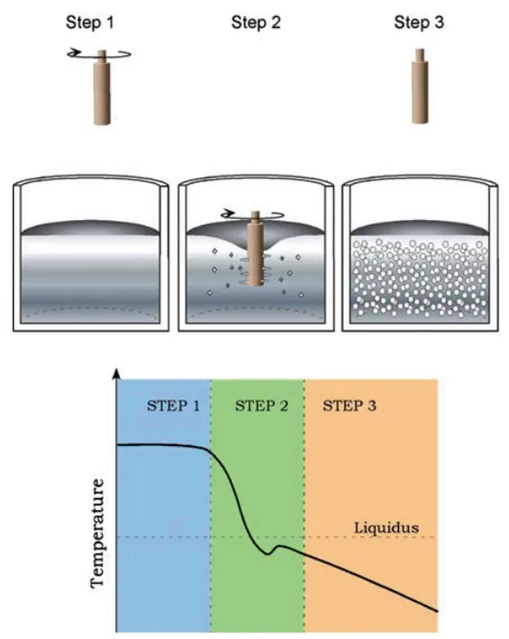
- Fig. 10.10 Schematic of the SSR process. Molten alloy is held above the liquidus (Step 1), then rapidly cooled and agitated for a controlled duration to a temperature below the liquidus (Step 2) before agitation and cooling ceases (Step 3).
- Fig. 10.11 SSR cell and graphite stirring rod in melt
- Fig. 10.12 Depicts the furnace and mixing configuration of DSF process with an anchor-shaped rotor with vertical shearing rods located close to the furnace walls for the scraping of solidifying material and vacuum drawing liquid aluminium through a tube into the shot sleeve of a cold chamber die casting press and photo insert the consistency of the slurry Reprinted with permission of ASM International(r). All rights reserved. www.asminternational.org
- Fig. 10.13 Schematic of a magnesium thixomoulding machine [7]
- Fig. 10.14 Schematic of Rheo-die casting process (RDC) [8]
- Fig. 11.1 Representative diaphragm style to minimise slug surface oxide entering the die cavity [10]
- Fig. 11.2 (a) Motorcycle swing arm mount, alloy 357, welded to 6,061 extrusions and heat treated by the customer, one-cavity die, (b) extrusion connector ATV frame, alloy 357, welded to 6,061 extrusions and heat treated by the customer and (c) flange for demolition hammer, alloy 319-T6 heat treated, two-cavity dies
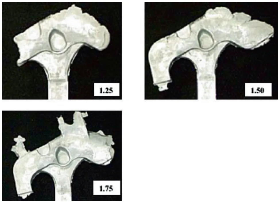
- Fig. 11.3 Fill test of the motorcycle swing arm mount showing 1.25%, 1.50% and 1.75% filling of the die cavity
- Fig. 11.4 (a) Die vacuum system with 7.5 HP pump and113.55L tank and (b) Vacuum runner for the part shown in Figure 11.5
- Fig. 11.5 Extrusion connectors produced without vacuum assist. Note non-fill areas (a) and Extrusion connectors produced with vacuum assist. Note all areas are now well filled
- Fig. 11.6 (a) Polished swing arm mount from Figure 4.21 (a), and (b) Chromium plated SSM cast part.
- Fig. 13.1 Parts produced by Stampal S.p.A for various automotive manufacturers using the MHD feedstock route
- Fig. 13.2 220t ThixomouldingR -machine from Japan Steel Works at Neue Materialien F¨urth GmbH (NMF)
- Fig. 13.3 Examples of magnesium thixomoulded parts from JSW Inc
- Fig. 13.4 Off-road motorcycle head-tube, alloy 357-T6 welded to a 6061 extrusion to make the complete frame (Vforge)
- Fig. 13.5 Small gasoline engine cartridge plate formed from alloy 357-T5, which replaced a machined alloy 6061-T6 piece (Vforge)
- Fig. 13.6 Small gasoline engine containing a number of SSM aluminium alloy parts including the entire crankcase, which is formed from alloy 357-T5 using a 2,500 ton machine and 5 in. diameter billet material. The cartridge plate in the previous figure and a companion SSM formed plate can be seen installed within the mechanism (Vforge)
- Fig. 13.7 Rheocast high strength safety parts: engine bracket (left) and Lagerbock (right) both using A 357 alloys (courtesy of Stampal S.p.A)
- Fig. 13.8 Air tank side parts for extruded tank profile; operating pressure 16 bar, very thin walls, 240 g each part using the MHD route. Material: New alloy, high YS (290 MPa) and E 12 (%) no H.T, low porosity, weldable, Audi. (Courtesy of SAG GmbH)
- Fig. 13.9 Left: Air manifold harness weldable on hydroformed part, thin wall, high ductility (VW and Audi) 130 g, replaces two parts previously produced by stamping. Front part of engine, vibration issues (fatigue); Centre: Antenna housing for tower mounted amplifier (TMA). Corrosion resistant, precision near net-shape, good surface quality, easy to coat (3–5 μm silver), with good electrical and inter-modulation properties; Right: Flange energy crash absorber; near net-shape component for AUDI A6 V8 energy management system for bumpers (Courtesy of SAG GmbH)
- Fig. 13.10 Decorative pen and cover SSM formed from aluminium alloy 6061 in order to achieve a very high lustre polish. Aluminium alloy 357 polished to a low lustre finish because of the silicon content, and so this was one of the very first wrought aluminium alloy production applications (courtesy Vforge)
- Fig. 13.11 Golf putter formed from alloy 357-T5 over a brass rod acting as a weight (Vforge)
- Fig. 13.12 One of the very first SSM copper alloy production parts. A golf driver sole plate formed from aluminium bronze alloy replacing a stamped and machined alloy 377 piece. This application offered improved wear resistance from the superior alloy as well as a near net-shape without machining requirements (Vforge)
- Fig. 13.13 Section views of the oil pump filter housing produced by SSR (Courtesy Idra Prince)
- Fig. 13.14 Orthopedic knee joint piece replaced an investment cast steel piece saving 0.25 lb weight per knee! Alloy 357-T5 (Vforge)
- Fig. 13.15 Some die cast dies can be converted to SSM forming provided the gating is acceptable for SSM die design as discussed above. This centre-gated die was converted relatively easily and runner volume saved by moving the shot position to dead centre (Vforge)
![Fig. 7.8 Shear rate jump from 1 to 100 s1 in SnPb alloy .fs D 0:36/ showing repeats of the same experiment and modeled fits using a spreadsheet and FLOW-3D predictions with a new ADI solver, which was introduced to address the challenges posed by fluids where the viscosity and shear rate change by many orders of magnitude in short times and spaces [76]](https://castman.co.kr/wp-content/uploads/image-3601.webp)
7. 結論:
半固体加工は、その発見から40年近くを経て、基礎科学的な理解と産業技術の両面で成熟期に入った。この技術は、デンドライト組織を球状化させることで得られる特異なレオロジー特性を利用し、従来の鋳造法では達成困難であった、ガス巻き込みや引け巣の少ない、熱処理可能な高品質・高信頼性部品のニアネットシェイプ製造を可能にする。長年の課題であった原材料コストは、ビレットを必要としない新しいレオキャスティング技術の登場によって克服されつつあり、これにより半固体加工は、自動車産業をはじめとする多くの分野で、従来のダイカストや鍛造に対するコスト競争力のある代替技術となる大きな可能性を秘めている。今後の普及拡大には、これらの新技術のさらなる安定化と、鉄鋼などの高融点合金への応用展開が鍵となる。
8. 参考文献:
- M.C. Flemings, Metall. Trans. A 22A, 957 (1991)
- M.C. Flemings, Solidification Processing (McGraw-Hill Book, New York, NY, 1974)
- W. Kurz, D.J. Fisher, Fundamentals of Solidification, 3rd edn. (Trans Tech, Switzerland, 1989)
- J.H. Holloman, D. Turnbull, Prog. Met. Phys. 4, 333 (1953)
- A.L. Greer, Philos. Trans. R. Soc. Lond. A 361, 479 (2003)
- I. Maxwell, A. Hellawell, Acta. Metall. 23, 229 (1975)
- D.B. Spencer, R. Mehrabian, M.C. Flemings, Metall. Trans. 3, 1925 (1972)
- P.A. Joly, R. Mehrabian, J. Mater. Sci. 11, 1393 (1976)
- C.J. Quaak, Ph.D. thesis, TU Delft, 1996
- S.A. Metz, M.C. Flemings, Trans. Am. Foundrymen’s Soc: 77, 329 (1969)
- S.A. Metz, M.C. Flemings, Trans. Am. Foundrymen’s Soc. 77, 453 (1969)
- D.P. Spencer, R. Mehrabian, M.C. Flemings, Metall. Trans. 3, 1925 (1972)
- K.P. Young, C. Rice, in Viscous, Semi-Solid Forging of Aluminum Reduces Costs and Boosts Alloy Flexibility, Aluminum USA, Navy Pier, Chicago, USA, 2003
- H. Kaufmann, H. Wabusseg, P.J. Uggowitzer, in Metallurgical and Processing Aspects of the NRC Semi-Solid Casting Technology, Aluminum, 76. Jg., 2000
- J.A. Yurko, R.A. Martinez, M.C. Flemings, in SSR: the Spheroidal Growth Route to Semi-Solid Forming, Proceedings of the 8th International Conference on Semi-Solid Processing of Alloys and Composites, Limassol, Cyprus, 2004
専門家Q&A:トップの質問に答える
Q1: 半固体加工における「レオキャスティング」と「チクソフォーミング」の根本的な違いは何ですか?
A1: 根本的な違いは、出発材料にあります。チクソフォーミングは、予め電磁攪拌などで製造された、球状の微細組織を持つ特殊な固体ビレットを再加熱して半固体状態に戻してから成形します。一方、レオキャスティングは、通常の溶湯(液体金属)から出発し、成形機の直前で冷却・攪拌して半固体スラリーを「その場で」生成し、成形します。
Q2: なぜ歴史的にチクソフォーミングが主流だったのですか?また、現在その状況はどのように変化していますか?
A2: 初期には、高品質なスラリーを安定して製造する技術が確立されていなかったため、品質が保証されたビレットを使用するチクソフォーミングが産業的に先行しました。しかし、ビレットが高価であることと、工程内で発生するスクラップ(ランナーやバリ)を自社で再利用できないというコスト上の大きな課題がありました。現在では、本書で紹介されているSSR法などの新しいレオキャスティング技術が登場し、低コストで高品質なスラリーを製造できるようになったため、コスト競争力が求められる自動車産業などを中心に、レオキャスティングへの回帰と普及が進んでいます。
Q3: 半固体加工に最適な固相率(固体粒子の割合)はどのくらいですか?
A3: 最適な固相率はプロセスによって異なります。チクソフォーミングの場合、ビレットの形状を保持しつつ、良好な流動性を得るために、固相率は0.5から0.6(50~60%)が最も効果的とされています(第1章)。一方、SSR法のようなレオキャスティングでは、液体に近い流動性を利用して従来のダイカストマシンに適用しやすくするため、固相率0.3(30%)以下の低い領域で運用されることが一般的です(第4章)。
Q4: 半固体加工は、どのようにしてガス巻き込みや引け巣といった欠陥を低減するのですか?
A4: 半固体スラリーは高い粘性を持ち、チクソトロピー性により力を加えると粘度が下がります。これにより、金型内を高速で飛散することなく、あたかも歯磨き粉を絞り出すように穏やかな「層流」で充填されます。このため、空気を巻き込むことが劇的に少なくなります。また、固液共存状態で圧力をかけるため、凝固収縮による最後の引け巣部分にも液体が供給されやすく、健全で緻密な組織が得られます。
Q5: チクソモールディングとは何ですか?また、なぜ主にマグネシウム合金で使われるのですか?
A5: チクソモールディングは、プラスチックの射出成形機に類似したスクリュー式の機械を用いて、マグネシウム合金のチップを半固体状態に加熱・混練し、射出成形するプロセスです(第10章)。マグネシウムはアルミニウムと異なり、鉄(スチール)との反応性が低いため、スチール製のスクリューやバレル内で加工が可能です。また、溶融状態のマグネシウムを扱わないため、燃焼のリスクを大幅に低減できるという安全上の大きな利点があり、主に携帯電話やノートPCの筐体など、薄肉・精密部品の製造に広く利用されています。
結論:高品質と高生産性への道を切り拓く
半固体加工は、従来の鋳造法が抱えるガス巻き込みや引け巣といった根本的な課題を、微細構造の制御という物理冶金学的なアプローチで解決する革新的な技術です。特に、本書で詳述されている最新のレオキャスティング技術は、長年の課題であったコストの壁を打ち破り、この優れた技術をより広範な産業分野に届ける可能性を秘めています。熱処理による高強度化と、ニアネットシェイプによる後加工の削減を両立できる半固体加工は、軽量化と高性能化が求められる現代の製品開発において、不可欠な選択肢となりつつあります。
CASTMANは、最新の業界研究を応用し、お客様の生産性と品質向上を支援することに尽力しています。本稿で議論された課題がお客様の事業目標と一致する場合、これらの原理を貴社のコンポーネントにどのように実装できるか、ぜひ当社のエンジニアリングチームにご相談ください。
著作権情報
このコンテンツは、David H. Kirkwood氏らによる論文「Semi-solid Processing of Alloys」に基づいた要約および分析です。
出典: DOI 10.1007/978-3-642-00706-4
この資料は情報提供のみを目的としています。無断での商業利用は禁じられています。 Copyright © 2025 CASTMAN. All rights reserved.