本紹介資料は、「[Politecnico di Torino (Master of Science Thesis)]」によって発行された論文「[Selective laser melting aluminum alloys for automotive component]」に基づいています。

1. 概要:
- タイトル: 自動車部品向けアルミニウム合金の選択的レーザー溶融 (Selective laser melting aluminum alloys for automotive component)
- 著者: Giulia Di Matteo
- 発行年: 2018
- 発行学術誌/学会: Politecnico di Torino (Master of Science Thesis)
- キーワード: 選択的レーザー溶融 (SLM), アディティブマニュファクチャリング, AlSi10Mg, アルミニウム合金, 自動車部品, 微細組織, 機械的特性, 異方性, 熱処理, 残留応力, 粉末特性評価. (明示的なキーワードがなかったため、本文内容に基づき推測)
2. 抄録:
選択的レーザー溶融(Selective Laser Melting)によって製造されたAlSi10Mgの特性に関する研究が、機械的および形態学的観点から実施されました。SLMおよび一般的なアディティブマニュファクチャリング技術によって実現される部品の本質的な特性の一つが高い異方性であることを考慮し、異なる造形方向が最終製品の特性に及ぼす影響が調査されました。さらに、熱処理を受けた材料と造形まま(as-built)の材料との間の機械的特性の比較、および粉末層の厚さの影響にも焦点が当てられました。この点に関して、AlSi10Mg合金の一連のサンプルがSLMプロセスを通じて作製されました。サンプルは、粉末層の厚さが異なる1つのケースを含む、4つの異なるジョブを通じて実現されました。試験片は2つの異なる造形方向でプリントされ、造形ままおよび処理された試験片の機械的挙動は、引張試験、HBマイクロ硬さ試験、およびシャルピー衝撃試験を通じて研究されました。最終製品の特性は、形状、粒子サイズおよび分布、組成などの粉末特性に依存するため、試験片の作製に使用された粉末も研究対象となりました。
3. 緒言:
アディティブマニュファクチャリング(AM)技術、特に選択的レーザー溶融(SLM)は、自動車や航空宇宙などの産業分野でますます不可欠なものとなっており、従来の製造技術に比べて多くの利点を提供しています。主な利点には、重量削減(部品の低密度化、組み立ての必要性をなくす部品の統合)、コスト削減(モデル、システムの設計段階のコスト排除、人件費削減)、およびオンデマンド生産(例:生産中止となった自動車のスペアパーツ)が含まれます。特にSLMは、最大99.9%の高密度金属部品の製造を可能にし、従来のプロセスでは製造できない非常に微細な微細組織と複雑な形状を実現します。この非常に微細な微細組織により、SLMプロセスを通じて作られた部品は、従来の生産プロセスと比較して改善された機械的特性を持つことができます。しかし、AMは、処理時間(速度)、潜在的な欠陥(表面粗さ、寸法精度)、層ごとの成長による固有の異方性、機械の寸法によって制限されるサイズ制限、機械および原材料の高コスト、サポート構造の必要性などの制限に直面しています。当初ラピッドプロトタイピング(RP)として知られていたAMは大幅に進化しましたが、金属部品、特に自動車産業におけるその応用は、ポリマーと比較して比較的新しい開発です。
4. 研究の要約:
研究テーマの背景:
アディティブマニュファクチャリング(AM)、特に選択的レーザー溶融(SLM)は、高品質で複雑な金属部品を製造するための成長分野であり、特に軽量で高性能な部品を求める自動車産業に関連しています。AlSi10Mgは自動車用途で使用される一般的な鋳造合金であり、SLMプロセスの候補材料となっています。
先行研究の状況:
SLM技術により、微細な微細組織を持つほぼ完全密度のAlSi10Mg部品の製造が可能です。しかし、プロセス誘起の異方性(造形方向による特性の変動)、気孔などの潜在的な欠陥、プロセスパラメータ(レーザー出力、スキャン速度、層厚、スキャン戦略)および後処理(熱処理)が最終特性に及ぼす影響などの課題が存在します。特にアルミニウム合金は、高い反射率、高い熱伝導率、酸化傾向、粉末流動性の問題により困難を伴います。
研究の目的:
本論文は、SLMによって製造されたAlSi10Mg合金の機械的および形態学的特性を調査することを目的としました。研究は以下の影響に焦点を当てました:
- 造形方向(異方性)。
- 後処理熱処理(応力除去)。
- 粉末層の厚さ。
中核研究:
本研究では、EOS M290 SLMシステムを使用して、異なる条件(4つの異なる「ジョブ」)下でAlSi10Mgサンプルを製造しました。2つの主要な造形方向(Z軸およびXY平面)が比較されました。サンプルは、造形ままの状態と応力除去熱処理(300°Cで2時間)後の両方で特性評価されました。1つのジョブでは、より厚い粉末層(0.03 mmに対して0.06 mm)が使用されました。開始粉末(2つのバッチ、AおよびB)も特性評価されました。特性評価方法には、密度および気孔率測定、光学顕微鏡(OM)、微細組織および破面分析のための走査型電子顕微鏡(SEM)、相特定および残留応力分析のためのX線回折(XRD)、引張試験、マイクロ硬さ試験(ブリネル)、およびシャルピー衝撃試験が含まれました。
5. 研究方法論
研究設計:
本研究では、異なる条件下でSLMによって製造されたAlSi10Mgサンプルを比較する実験計画を採用しました。主な変数は以下の通りです:
- 開始粉末バッチ(AおよびB)。
- SLMプロセスパラメータ(EOS M290を使用したJob A、B、C、Dによって定義)。
- 造形方向(Z軸に沿って造形されたサンプル vs. XY平面で造形されたサンプル)。
- 粉末層厚(Job Cは0.06 mmを使用、他は0.03 mmを使用)。
- 後処理熱処理(造形まま vs. 300°Cで2時間の応力除去)。
データ収集および分析方法:
- 粉末特性評価:
- 流動性: 50gが2.5mmオリフィスを流れる時間を測定。
- タップ密度: タッピングシステム(Figure 23)を使用して圧縮性指数(CI)およびハウスナー比(HR)を計算(Equations 5, 6)。
- 粒子サイズ分布: LASER PARTICLE SIZER ANALYSETTE 22 NANOTEC(Figure 25)、湿式分散。
- 形態: 走査型電子顕微鏡(SEM)。
- 相組成: X線回折(XRD)。
- サンプル特性評価:
- 密度および気孔率: アルキメデス天秤(Figure 26)を使用し、Equations 6, 7, 8, 9, 10, 11, 13を用いて計算。サンプルは最初に機械的に研磨。
- 微細組織: 光学顕微鏡(OM)(Leica DMI 5000 M)を用いて研磨およびエッチング(Keller試薬)された断面(造形方向に平行および垂直)を観察。詳細な形態および破面分析のための走査型電子顕微鏡(SEM)(Leo 435VP)(Figure 32)。
- 相特定: X線回折(XRD)(Panalytical X’PERT PRO PW3040/60, Cu Kα)。
- 残留応力: GNR Stress X回折計(Figure 27)を用いたsin²ψ法によるX線回折(XRD)分析、成長方向に対して平行および垂直な面を分析(Equations 14-21, Figures 28-31)。
- 機械的特性:
- 引張試験: UNI EN ISO 6893に従い、MTS CITERION MODEL 43およびGALDABINI mod. SUN40機を使用(Figure 34)。Rm、Rp、伸びを計算(Equations 22, 23)。
- マイクロ硬さ試験: UNI EN 6506-1に従うブリネル硬さ(HB)、EMCOTEST M5U 300/030機(Figure 36)を使用、2.5 mmタングステンカーバイド球、10 N荷重で10秒(Equations 24, 25, 26)。平行および垂直な面で測定。
- シャルピー衝撃試験: ASTM E 23に従い、ノッチ付きサンプルを使用(Figure 37)。
研究トピックおよび範囲:
本研究は、潜在的な自動車用途向けのAlSi10Mg合金のSLMプロセスに焦点を当てました。範囲には以下が含まれます:
- 開始AlSi10Mg粉末(EOS供給、2バッチ)の特性評価。
- 定義されたプロセスパラメータ(Figure 18 / Figure 42)を持つEOS M290 SLM機を使用した試験片の製造。
- 造形方向(Z vs. XY, Figure 9, Figure 21)が材料特性に及ぼす影響の調査。
- 標準的な応力除去熱処理の効果の評価。
- 増加した粉末層厚(Job C)の影響の評価。
- 製造されたサンプルの密度、気孔率、微細組織、相組成、残留応力、および機械的特性(引張、硬さ、衝撃靭性)の包括的な特性評価。
6. 主要な結果:
主要な結果:
- 粉末: 2つのバッチ(A、B)が使用されました。両方ともガスアトマイズプロセスの典型的なほぼ球形の形態を示し、いくつかのサテライト/凝集体が見られました(Figure 38)。平均粒子サイズは両方の粉末で約27 μmでした。粉末Bは、粉末A(流動せず)よりも良好な流動性(65秒/50g)と低い圧縮性指数/ハウスナー比を示しました。これは粒子サイズ分布の違い(粉末Bはより粗く、狭い分布を持つ、Figure 39, Table 6)に起因します。XRDは、バージン粉末中の主要な結晶相がAlとSiであることを確認しました(Figure 40)。SLMジョブ後に回収された粉末のスペクトルでは、Siピーク強度が増加しており、熱暴露によるSiの結晶化改善を示唆しています(Figure 41)。
- 密度と気孔率: すべてのSLMサンプルは、EOSデータシート値(約1%)と比較して低い密度と高い気孔率(1.6-2.1%)を示しました(Table 7)。気孔は特に溶融プールエッジで顕著であり、不完全な固化を示唆しています。熱処理も粉末層厚の増加も、全体の密度や気孔率に有意な影響を与えませんでした(Figure 43)。気孔は一般的に10 μm未満でした(Figure 44)。
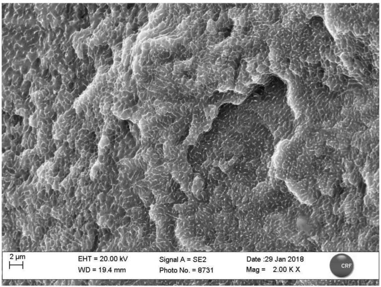
- 微細組織: サンプルは、SLMにおける急速凝固に特徴的な非常に微細な微細組織を示しました。光学顕微鏡写真は溶融プール構造を明らかにしました(Figure 43)。造形方向に平行な断面は、層状の半円筒形の溶融プールを示しました。垂直な断面は、熱勾配とマランゴニ効果により、細長い溶融プールを示しました(Figure 44)。破面のSEM分析では、粒界にSiが偏析した小さな(< 2 μm)α-Al粒で構成されていることが示されました(Figure 55)。
- 引張特性: 機械的特性は、造形方向、熱処理、粉末層厚に強く依存しました(Figures 45-49, Table 8, Table 9)。
- 異方性: Z軸サンプルはXY平面サンプルと比較して高い引張強さ(Rm)を示しましたが、低い降伏強さ(Rp)と伸びを示しました。
- 熱処理: 応力除去は一般的にRm(約13-20%減少)とRp(約12-18%減少)を減少させましたが、伸びを大幅に増加させました(Job Aで約20%、Job B Z軸で最大70%)。この効果はZ軸サンプルでより顕著でした。
- 層厚: より厚い層で作られたサンプル(Job C)は、薄い層で作られたサンプルと比較して、熱処理後の機械的特性の変化がはるかに少なかったです。
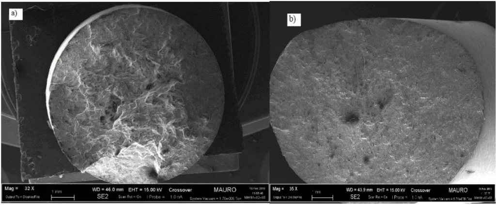
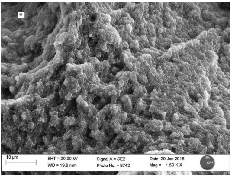
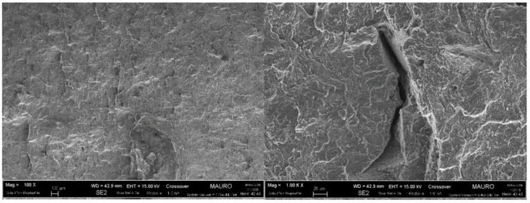
- 破壊メカニズム: SEMは、低倍率で粒界間延性破壊(特にZサンプルについて、溶融プール間の分離、Figure 52a)を示しました。高倍率では、粒界延性破壊(マイクロボイドコアレッセンス、ディンプル)が観察されました(Figure 53, Figure 55)。熱処理は粒界でのSi偏析(およびおそらくMg2Si形成)を促進し(Figure 57)、粒成長を妨げましたが、特性変化に寄与しました。Zサンプルの破壊は層(弱い界面)に対して垂直に伝播しましたが、XYサンプルでは層(Figure 51)に対して平行に伝播しました。
- 硬さ: 硬さは異方性を示しました。成長方向(Z軸)に垂直な面は、平行な面よりも一貫して高いHB値を示しました(Table 11)。これは異なる熱履歴に起因します:垂直な面は急速冷却を伴う最後の凝固層を表す一方、平行な面は造形中に高温に長時間さらされ、ある程度の応力緩和/軟化が起こるためです。熱処理は硬さ値に有意な影響を与えませんでした。これは、造形まま部品の硬さが主に微細な微細組織と残留応力によるものであり、熱処理中のMg2Si析出が応力緩和を補償することを示唆しています。SLM硬さは標準的な鋳造AlSi10Mgと同等かそれ以上でしたが、析出硬化(T6)または高圧ダイカストおよび時効処理された材料よりは低かったです(Table 12)。
- シャルピー衝撃: 明確な異方性が観察されました。XY平面サンプルは、造形ままおよび熱処理済みの両方で、Z軸サンプルよりも有意に多くのエネルギーを吸収しました(より高い靭性)(Table 13)。これは層の向きに対する亀裂経路によるものです(Figure 59)。熱処理は両方の方向で吸収エネルギー(破壊靭性)を大幅に増加させ、Z軸サンプルでは約5倍の劇的な増加が見られました。
- 残留応力: XRD分析により、平行および垂直な面の両方で圧縮応力とせん断応力の複雑な状態が明らかになりました(Figures 60, 61, 63, 64)。成長方向に垂直な面でより高い圧縮応力が測定され、これは硬さの結果および熱履歴と一致しています。過飽和固溶体中のSiの存在は、格子を歪ませ、応力測定の絶対精度に影響を与えた可能性があります(d間隔の変動)。熱処理は圧縮/軸応力成分にはほとんど影響を与えませんでしたが、せん断応力の大幅な減少をもたらしました(Figure 62, 63, 64)。
図の名称リスト:
- Figure 1 : Comparison between AM costs and conventional methods ones[4]
- Figure 2 : Common metal additive manufacturing process[7]
- Figure 3 : EBM schematic representation
- Figure 4: schematic representation of LPBF process [8]
- Figure 5: schematic representation of SLM process
- Figure 6: scheme of LMD process
- Figure 7: Schematic representation of the SLM process
- Figure 8 The schematic of hatch angle in raster filling patterns
- Figure 9: different building orientation a) z plane b) c) xy plane
- Figure10: solid-liquid system wettability
- Figure11: schematic representation of water atomization process
- Figure 12 : schematic representation of plasma atomization process
- Figure 13 : schematic representation of centrifugal atomization
- Figure 14: schematic representation of gas atomization process
- Figure15: state diagram Al-Si
- Figure 16 : EOS M290 [27] system and its technical data
- Figure 17: Different scanning strategies.
- Figure18 : Eos M290 process parameters
- Figure 20: cubic and parallelepiped samples
- Figure 21: main samples geometries a), d) samples with building orientation along z-axes , b), c) samples with building orientation in x-y plane
- Figure 22: charpy test samples
- Figure 23 : tapping system
- Figure 24 : determination flow character through Hausner ratio e compress index
- FGUR E 25: ANALYSETTE 22 Nanotec
- Figure 26 : Archimede’s balance
- Figure 27 : CRF Metals Lab diffractometer
- Figure 28: Positions of XR source and detector for resisual stress measurements.
- Figure 29 Effect of stress on plane spacing in crystals with different orientation.
- Figure 30 Calculation of residual stress from the slope of the plot
- Figure 31 : inter-planar distance as a function of sin2 ψ a) Regular behavior b) ψ splitting c) Oscillatory -indicating the presence of an inhomogeneous stress/strain state within the material [30]
- Figure32: scheme of SEM
- Figure 33: tensile test sample a) before testing b) after testing
- Figure 34: MTS CITERION MODEL 43 machine
- Figure 35 : principle measurement of the Brinell hardness.
- Figure 36 : Brinnel EMCOTEST M5U 300/030 machine [ 30]
- Figure 37: ASTM E23 Charpy samples
- Figure 38 : SEM image of the two AlSi10Mg powders: A) first batch and B) second batch
- Figure 39 : particle size distribution; A virgin powder and B virgin powder
- Figure 40 : A and B virgin powder spectra
- Figure 41 : XRD spectrum of powder A: a) comparison among virgin powder, powder collected after DMLS job and as residual coming from nozzle; b) zoom on Si peak.
- Figure 42: jobs process parameters
- Figure 43: Job A as built and heat treated samples micrographs (magnification 50 x): on the left is presented the section parallel to the building direction, on the right the perpendicular one.
- Figure 44 :Typical microstructure morphology of Laser Melted parts: on the left the section parallel to the building direction (Z axis); on the right the section perpendicular to the building direction( Z axis)
- Figure 45 : Job A, Z samples as built and heat treated ,Stress-strain curves.
- Figure 46: Job A, XY samples as built and heat treated ,Stress-strain curves.
- Figure 47: Job B, Z samples as built and heat treated ,Stress-strain curves.
- Figure 48: Job B, XY samples as built and heat treated ,Stress-strain curves.
- Figure 49: Job C, XY samples as built and heat treated ,Stress-strain curves
- Figure 50: a) Z samples fracture surface b) XY samples fracture surface
- Figure 51 : Schematic representation of interactions between building orientation and the stress direction : a) Z samples b) XY samples
- Figure 52 : a) as built Z samples fracture surface (100x) b) as built XY samples fracture surface higher magnitude (100X)
- Figure 53 : as built Z sample fracture surface magnitude 1,50K,x
- Figure 54 : Al-Si phase diagram
- Figure 55 :Fracture surface os Z samples at high magnification: aluminum grains smaller than 2 µm with silicon segregation at the grain boundaries.
- Figure 56 :heat treated Z samples inter-domain fracture surfaces different magnitude
- Figure 57: Enhanced segregation at grain boundaries of silicon that hinders the aluminium grain growth during the heat treatment.
- Figure 58 :heat treated XY samples fracture surfaces, different magnifications
- Figure 59 : cross section of Charpy samples ,different layers orientation with respect to V notch for samples built along Z axis and on XY plane
- Figure 60: residual stress analysis on the perpendicular face of the as built sample
- Figure 61: residual stress analysis on the parallel face of the as built sample
- Figure 62: Temperature gradient influences on the formation of residual stress
- Figure 63: residual stress analysis on the perpendicular face of the heat treated sample
- Figure 64: residual stress analysis on the parallel face of the heat treated sample
7. 結論:
AlSi10Mg合金の試験片がレーザービーム溶融(SLM)技術によって製造され、特性評価されました。主要な結論は以下の通りです:
- すべてのサンプルは、製造元(EOS)のデータシート値よりも低い密度と高い気孔率を示しました。これは、溶融プールエッジでの不完全な固化による可能性が高いです。最終的な密度と気孔率は、熱処理や粉末層の厚さによって有意な影響を受けませんでした。
- 引張試験により、機械的特性は成長方向、熱処理、粉末層の厚さに依存することが確認されました。Z軸サンプルはXY平面サンプルよりも高い引張強さを示しましたが、降伏強さと伸びは低かったです。応力除去熱処理は、主に伸びを増加させ、強度を減少させました(特にZ軸サンプルで)。より厚い粉末層は熱処理の影響を減少させました。
- 電子顕微鏡観察により、粒界にシリコンが偏析した非常に小さなアルミニウム粒からなる微細組織が明らかになりました。破壊は、粒界間および粒界延性破壊メカニズムによって発生しました。熱処理はシリコン偏析を促進し、有意な粒成長を妨げました。
- 材料の異方性は、硬さと破壊仕事に影響を与えました。硬さは、異なる熱履歴のため、成長方向に垂直な面で高かったです。応力除去は硬さを有意に変化させませんでした。破壊仕事(シャルピー)はXY平面サンプルで高く、熱処理後に大幅に増加しました(特にZ軸サンプルで)。
- 残留応力分析により、成長方向に垂直な面でより高い、圧縮応力とせん断応力の複雑な状態が示されました。固溶体中のシリコンの存在は、応力評価の精度に影響を与えました。応力除去処理後、せん断応力の大幅な減少が観察されました。
8. 参考文献:
- [1] M. Javidani, J. Arreguin-Zavala, J. Danovitch, Y. Tian, and M. Brochu, “Additive Manufacturing of AlSi10Mg Alloy Using Direct Energy Deposition: Microstructure and Hardness Characterization,” J. Therm. Spray Technol., vol. 26, no. 4, pp. 587–597, 2017.
- [2] I. Campbell, D. Bourell, and I. Gibson, “Additive manufacturing: rapid prototyping comes of age,” Rapid Prototyp. J., vol. 18, no. 4, pp. 255–258, 2012.
- [3] S. H. Huang, P. Liu, A. Mokasdar, and L. Hou, “Additive manufacturing and its societal impact: A literature review,” International Journal of Advanced Manufacturing Technology, vol. 67, no. 5–8. pp. 1191–1203, 2013.
- [4] W. E. Frazier, “Metal additive manufacturing: A review,” Journal of Materials Engineering and Performance, vol. 23, no. 6. pp. 1917–1928, 2014.
- [5] N. Guo and M. C. Leu, “Additive manufacturing: Technology, applications and research needs,” Frontiers of Mechanical Engineering, vol. 8, no. 3. pp. 215–243, 2013.
- [6] S. Trouton, “A Deloitte series on additive manufacturing,” Deloitte Univ. Press, 2016.
- [7] V. Bhavar, P. Kattire, V. Patil, S. Khot, K. Gujar, and R. Singh, “A Review on Powder Bed Fusion Technology of Metal Additive Manufacturing,” Mater. Sci. Technol. 2014, pp. 251–262, 2014.
- [8] J.-P. Kruth, “Materials and Processing Issues in Powder Fusion Additive Manufacturing,” 2013.
- [9] R. M. Mahamood, E. T. Akinlabi, M. Shukla, and S. Pityana, “Material Efficiency of Laser Metal Deposited Ti6A14V: Effect of Laser Power,” Eng. Lett., vol. 21, no. 1, pp. 18–22, 2013.
- [10] B. Liu, R. Wildman, C. Tuck, I. Ashcroft, and R. Hague, “Investigation the effect of particle size distribution on processing parameters optimisation in selective laser melting process,” Int. solid Free. Fabr. Symp. an Addit. Manuf. Conf., no. mm, pp. 227–238, 2011.
- [11] A. Aversa et al., “Effect of Process and Post-Process Conditions on the Mechanical Properties of an A357 Alloy Produced via Laser Powder Bed Fusion,” Metals (Basel)., vol. 7, no. 3, p. 68, 2017.
- [12] K. H. Leitz et al., “Fundamental analysis of the influence of powder characteristics in Selective Laser Melting of molybdenum based on a multi-physical simulation model,” Int. J. Refract. Met. Hard Mater., vol. 72, no. December 2017, pp. 1–8, 2018.
- [13] D. Manfredi, F. Calignano, M. Krishnan, R. Canali, E. P. Ambrosio, and E. Atzeni, “From powders to dense metal parts: Characterization of a commercial alsimg alloy processed through direct metal laser sintering,” Materials (Basel)., vol. 6, no. 3, pp. 856–869, 2013.
- [14] N. Kang, P. Coddet, L. Dembinski, H. Liao, and C. Coddet, “Microstructure and strength analysis of eutectic Al-Si alloy in-situ manufactured using selective laser melting from elemental powder mixture,” J. Alloys Compd., vol. 691, pp. 316–322, 2017.
- [15] A. Aversa, “Development and Characterisation of Aluminium Alloys and Aluminium Matrix Composites Produced via Laser Powder Bed Fusion By,” 2017.
- [16] I. Yadroitsev, L. Thivillon, P. Bertrand, and I. Smurov, “Strategy of manufacturing components with designed internal structure by selective laser melting of metallic powder,” Appl. Surf. Sci., vol. 254, no. 4, pp. 980–983, 2007.
- [17] K. G. Prashanth et al., “Microstructure and mechanical properties of Al-12Si produced by selective laser melting: Effect of heat treatment,” Mater. Sci. Eng. A, vol. 590, pp. 153–160, 2014.
- [18] K. Kempen, L. Thijs, J. Van Humbeeck, and J.-P. Kruth, “Mechanical Properties of AlSi10Mg Produced by Selective Laser Melting,” Phys. Procedia, vol. 39, pp. 439–446, 2012.
- [19] L. Wang, J. Jue, M. Xia, L. Guo, B. Yan, and D. Gu, “Effect of the Thermodynamic Behavior of Selective Laser Melting on the Formation of In situ Oxide Dispersion-Strengthened Aluminum-Based Composites,” Metals (Basel)., vol. 6, no. 11, p. 286, 2016.
- [20] J. Kruth, P. Mercelis, J. Van Vaerenbergh, and T. Craeghs, “Feedback control of Selective Laser Melting,” Proc. 3rd Int. Conf. Adv. Res. Virtual Rapid Prototyp., pp. 1–7, 2007.
- [21] M. Entezarian, F. Allaire, P. Tsantrizos, and R. A. L. Drew, “Plasma atomization: A new process for the production of fine, spherical powders,” JOM, vol. 48, no. 6, pp. 53–55, 1996.
- [22] EOS GmbH - Electro Optical Systems, “Material information Compatibility DMLS Materials – EOSINT M 280,” p. 82152.
- [23] S. Hegde and K. N. Prabhu, “Modification of eutectic silicon in Al-Si alloys,” J. Mater. Sci., vol. 43, no. 9, pp. 3009–3027, 2008.
- [24] W. Li et al., “Effect of heat treatment on AlSi10Mg alloy fabricated by selective laser melting: Microstructure evolution, mechanical properties and fracture mechanism,” Mater. Sci. Eng. A, vol. 663, pp. 116–125, 2016.
- [25] N. T. Aboulkhair, N. M. Everitt, I. Ashcroft, and C. Tuck, “Reducing porosity in AlSi10Mg parts processed by selective laser melting,” Addit. Manuf., vol. 1, pp. 77–86, 2014.
- [26] B. Duman and M. C. Kayacan, “Doğrudan Metal Lazer Sinterleme / Ergitme Yöntemi ile İmal Edilecek Parçanın Mekanik Özelliklerinin Tahmini Predicting The Mechanical Properties Of The Part Produced By Direct Metal Laser Sintering / Melting Method,” 2017.
- [27] EOS GmbH, “EOS M290 Datasheet Status 09/2017,” 2017.
- [28] A. Popovich and V. Sufiiarov, “Metal Powder Additive Manufacturing,” New Trends 3D Print., 2016.
- [29] Fritsch, “Operating Instructions Analysette 22.”
- [30] M. Fitzpatrick, A. Fry, P. Holdway, F. Kandil, J. Shackleton, and L. Suominen, “Determination of Residual Stresses by X-ray Diffraction - Issue 2,” Meas. Good Pract. Guid., no. 52, p. 74, 2005.
- [31] JEOL, “Scanning Electron Microscope A To Z,” Serv. Adv. Technol., p. 32, 2006.
- [32] 1.Rosenthal, I., Stern, A. & Frage, N. Strain rate sensitivity and fracture mechanism of AlSi10Mg parts produced by Selective Laser Melting. Mater. Sci. Eng. A 682, 509–517 (2017).
- [33] 1.Mertens, A., Dedry, O., Reuter, D., Rigo, O. & Lecomte-Beckers, J. THERMAL TREATMENTS OF AlSi10Mg PROCESSED BY LASER BEAM MELTING. 1007–1016
- [34] 1.Aboulkhair, N. T., Everitt, N. M., Ashcroft, I. & Tuck, C. Reducing porosity in AlSi10Mg parts processed by selective laser melting. Addit. Manuf. 1, 77–86 (2014).
9. 著作権:
- 本資料は「Giulia Di Matteo」氏の論文です。「Selective laser melting aluminum alloys for automotive component」に基づいています。
- 論文の出典: 利用不可 (修士論文, Politecnico di Torino)
本資料は上記の論文に基づいて要約されており、商業目的での無断使用は禁じられています。
Copyright © 2025 CASTMAN. All rights reserved.


